SensAble AccSens Plus User manual

1
Sep 2003
Revision: 04
Proximity Controller AccSens Plus
INSTALLATION MANUAL
Part Number: MIC0302050
AccSens Plus
Proximity Controller

2
AccSens Plus Proximity Controller
Part 1: Installation Manual
1.1 Introduction
The AccSens Plus stand-alone proximity controller provides total control of up to 8 independent access
points and two thousand users without the requirement of a personal computer or expensive software
associated with online systems. The controller allows for real-time serial printing of all transactions, with
a memory buffer of 500 date/time stamped transactions.
1.2 Installation Planning
When planning your installation it is important to map out the locations of your readers and your
AccSens Plus programming unit. Up to 7 PicoProx reading heads can be networked, so plan your
locations so as to ensure easy cabling between readers. Ideally the AccSens Plus programming unit
should be in a secure yet central position where a supply point is available preferably without a switch.
Choosing the right locking mechanism:
There are many different types of locks on the market today, which require different electrical wiring
depending on the type of lock you want to use.
The three more commonly used locking systems are:
•Fail – secure door strike: This system requires electrical power to unlock the door. In the event
of a power failure or if the power cable is cut, then the door remains securely locked and access
is denied.
•Fail – safe door strike: This system requires electrical power to lock the door. In the event of a
power failure or if the power cable is cut, then the door unlocks and access is granted.
•Magnetic door lock (Mag. Lock): This system uses a very strong electromagnet to lock the
door, and this electromagnet is energized when power is supplied. Due to its design it is
inherently a fail – safe system. When power is not supplied the door unlocks and access is
granted.
•Note: Please adhere to local authority safety regulations when choosing your door lock system.
For example in the event of a fire it is possibly a requirement for all doors to be opened
automatically via a command from a fire alarm panel.
3
Reception
Door 7
Passage door 1
Door 6
Door 2
Door 3
Door 4
2
2
Power
Inputs
~ ~
n
c n
o
c
o
m
n
c n
o
c
o
m
E
X
T
1
E
X
T
2
B A
C
T
L
1
C
T
L
2
T
X R
X
F 1
J2
HI
12V DC
0V
Door
Mag. lock
RTE
Button
Alarm
Mains
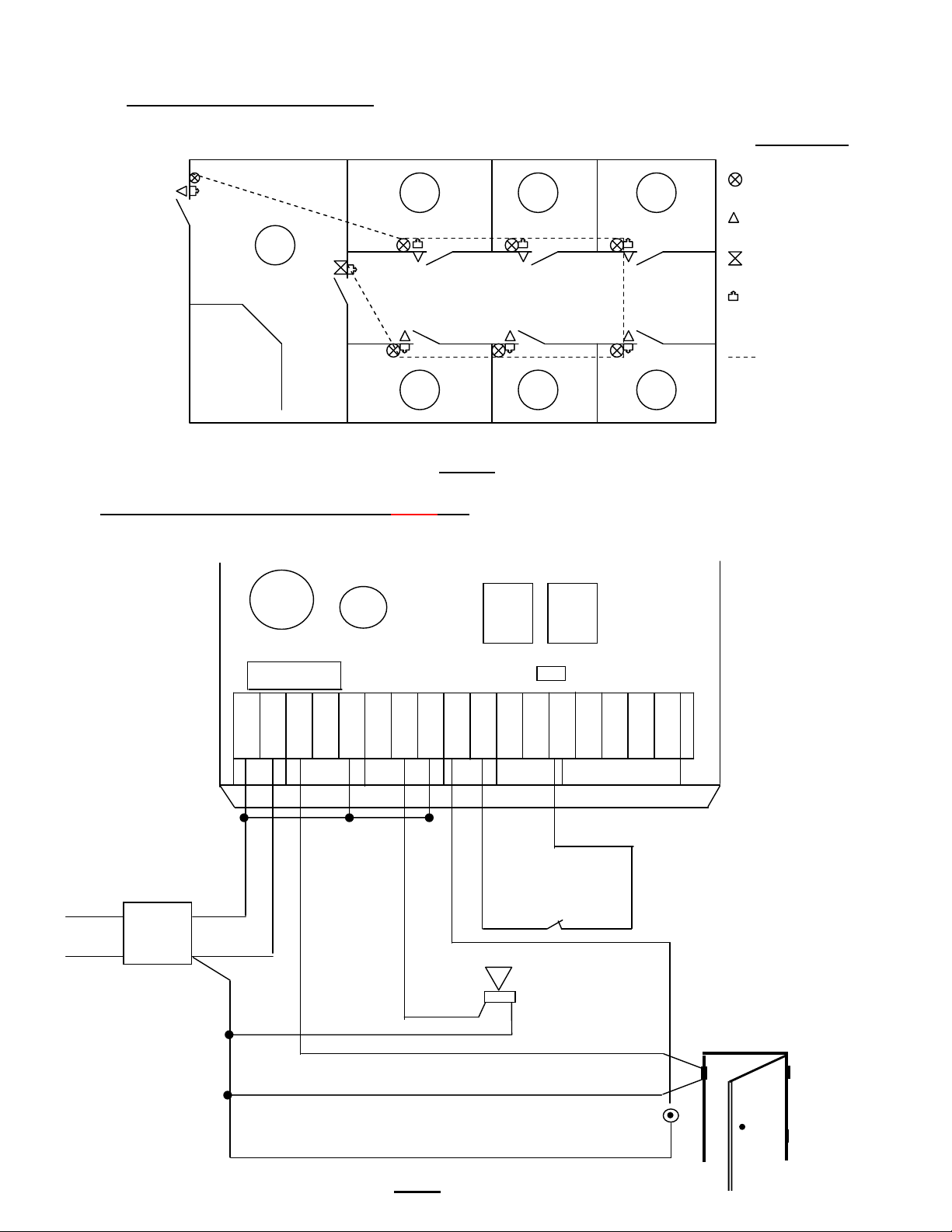
Fig.02
Fire Alarm Input
Normally closed contact
1.3 Example of installation layout:
Symbol Key:
MiniNode
Pico Prox
AccSens Plus
RTE
(Request to Exit)
Cable route
Fig. 01
1.4 Installation and wiring of AccSens Plus unit
Once the AccSens Plus has been mounted in the correct position the following electrical wiring needs
to be followed: Refer to Fig. 02:
Door 5
1
3
4
5
6
7
Relay 1
Relay 2
RS485
RS 232
G
N
D
C3 L1
RLY
1
RLY
2
Power
Supply
2A

4
Step1:
From the positive (12V DC) leg of your power supply (preferably a 2A supply), take a wire to the first
terminal (~) on the AccSens Plus unit and bridge it out with the common of relay 1 and also to the
common of relay 2.
Step 2:
From the negative (0V) leg of your power supply, take a wire to the second terminal (~) on the
AccSens Plus unit. At the same time run a wire to the negative side of your alarm, then run another
wire from the negative side of your alarm to the negative of your magnetic lock/electric lock which is
also bridged to the one side of your RTE (Request To Exit) button. A GND also needs to be wired to the
normally closed contact (NC) in your fire alarm panel if you have one installed.
Step 3:
From the NC terminal of relay 1 on the AccSens Plus unit, run a wire to the positive leg of your
magnetic lock (fail-safe), or from the NO terminal if you have an electric strike (fail-secure).
Step 4:
From the NO terminal of relay 2 on the AccSens Plus unit, run a wire to the positive leg of your
Alarm.
Step 5:
The fire alarm and the RTE button are both external inputs. You will need to run a wire from the EXT 1
(inputs) terminal to the vacant terminal on the RTE button. Another wire must then be run from the EXT
2 (inputs) terminal to the other side of the NC contact of your fire alarm panel.
1.5Adding doors to your system
In order to commence adding doors to your AccSens Plus system a RS485 cable needs to be run
along the route of your door locations, for example refer to Fig.01.
The RS485 cable
Twisted pairs: This cable should ideally be a shielded category 5 cable with twisted pairs. The A and B
lines must always be on the same pair ie. A is red and B is red/blue or visa versa.
Shielding: The shield must only be grounded at one end, if the shield is grounded at both ends then a
ground loop may occur which will effect the efficiency of the communication.
Cable length: RS485 can be run over a maximum distance of 1000m, however longer runs are possible
if a quality cable is used and there is no noise along the run. However if your run is less than 100m then
your cable does not need to be shielded.
Topology: RS485 is intended for a single run type application, and teeing off in a star formation should
not be attempted as this could affect the system. Below are some examples of the correct and incorrect
tee off methods.

5
To next door location .
(+)
Mag Lock.
(+)(–)
(–) (+)
RS 485
RS 485
(-)
12V DC
0V
Black
Red
Yellow
Black
Green
Blue
Once your cable has been run you are then ready to wire up the remainder of your access control
system in a daisy chain type formation. The wiring is done according to Fig.03 below.
There are a number of options to choose from when selecting your reader head. The following options
are examples of the options available to you:
•MiniNode + Pico Prox. (clock & data) proximity reader
•MiniNode + DorMag. (clock & data) magnetic swipe reader
•RS485 Pico Prox. proximity reader with on-board relay
•RS485 DorMag. magnetic swipe reader with on-board relay
Note: Other reader head options are available but have not been included on this list. It must also be
noted that not all of the wiring diagrams have been included in this installation manual, as each
individual reader head product will have the wiring instructions for that particular product in their
packaging.
1.5.1 Wiring of MiniNode and Pico Prox reader
The following steps should be followed for each door location. The very last door location on the RS485
network will need a 150 Ωresistor across the communication line to prevent data reflection.
Step 1:
From the RS485 cable that you have just run, cut the cable at the first door location and take the end
which is wired to the AccSens Plus unit and wire the positive (+) line into terminal 14 of your
MiniNode. Wire the negative (-) line into terminal 13 of your MiniNode. The remaining end of the cable
which you have just cut must also be wired positive line into terminal 14 and negative line into terminal
13 respectively. (Daisy chain formation)
7
1 2 3
4
5
6
14 13 12 11 10 9
RESET
BUTTON
8
Power
Supply Door Position Switch
RTE Button
230V
Fig. 03

6
Step 2:
Now you can wire in your Pico Prox reader into terminals12, 11, 10, 9 and 8 of your MiniNode as
follows:
MiniNode Terminal Description Reader head Cabling Description
Terminal 8 Reader head LED control Blue LED Control
Terminal 9 Data line Green DATA Line
Terminal 10 Clock line Yellow CLOCK Line
Terminal 11 5V DC 100mA Red 5V DC
Terminal 12 Ground Black 0V GND
NOTE: Please refer to the instruction sheet of other reader heads for the relevant wiring details.
Step 3:
A wire from the 12V DC side of the power supply must be wired into terminal 1(Power – positive) and
the 0V line of the power supply must be wired into terminal 2 (Power – negative).
1.5.2 Wiring in the magnetic lock / electric lock (Fail-Safe locks)
Step 1:
Take a wire from your 12V DC power supply and wire it into the positive side of your magnetic lock.
Step 2:
Then you must run a wire from your 0V side of your power supply to the common of your on board relay
which is terminal 5 on the MiniNode.
Step 3:
Then from terminal 3 of the MiniNode, which is your normally closed contact, run a wire to the negative
side of your magnetic lock. You now have both a positive and negative on your magnetic lock.
Note: A fail-secure lock would need to be wired via the normally open relay contact, which is terminal 4
on your MiniNode.
1.5.3 Wiring in External inputs (Request to exit pushbutton/ Door position switch)
Step 1:
The RTE (Request to exit) pushbutton enables a “free exit” function on locked doors.
From the one side of your RTE pushbutton run a wire to the OV leg of your power supply and then from
the other side of the RTE pushbutton run a wire to terminal number 6 on your MiniNode.
Step 2:
The door position switch, normally open magnetic type door contact, for monitoring the position of the
door. From the one side of your door position switch run a wire to the 0V leg of your power supply and
then from the other side of the door position switch run a wire to terminal number 7 on your MiniNode.
NOTE: The door position switch is used to activate the alarm (refer to Fig.03) if the door is left open for
longer than the preset time. (See the programming manual page 7 {4.3})

7
Power
Inputs
~ ~
n
c n
o
c
o
m
n
c n
o
c
o
m
E
X
T
1
E
X
T
2
A B
C
T
L
1
C
T
L
2
T
X R
X
1
5
6
9
13
1
RS232 Serial Printer
(DB
–
25M)
F 1
J2
HI
PC Com1 / Com2
(DB – 9F)
AccSens
Plus
NC contact or
Pushbutton on fire
alarm panel
E
X
T
2
AccSens
Fig.04
G
N
D
1.5.4 Wiring of fire emergency switch:
In case of emergency all doors can be opened at once by opening the emergency input (EXT 2) of the
AccSens Plus unit via a latching normally closed contact of the fire alarm panel. The doors will remain
open, relay 2 will be energized and EMERGENCY is displayed on the AccSens Plus unit, until such
time as the fire alarm panel has been reset and the Master card/tag has been presented to the AccSens
Plus unit.It is important to reset the fire alarm panel first before presenting your Master card to the
AccSens Plus unit. If a non – latching contact is used and this input receives a short trigger, the doors
will remain open and the alarm will be triggered until such time that a master card/tag is presented to
the AccSens Plus unit.
1.6Wiring of RS232 serial printers and / or terminal
Fig.05
Relay 1
Relay 2
RS485
RS 232
G
N
D
C3 L1
RLY
1
RLY
2

8
1.6.1 Wiring of DB – 25M Connector
Refer to Fig.05. Connect a 5 core comms cable between your AccSens Plus unit and the printer and
do the following:
Step 1:
Make a connection between the GND terminal on the AccSens Plus unit and pin number 7 (GND) on
your RS232 DB – 25M connector.
Step2:
The CTL 1 terminal is connected to pin number 5 on your RS232 DB – 25M connector.
Step 3:
The CTL 2 terminal is then connected to pin number 4 on your RS232 DB – 25M connector .
Step 4:
The TX terminal is connected to pin number 3 (RX) on your RS232 DB – 25M connector.
Once those connections have been made you can plug in your serial printer and it will work online.
1.6.2 Wiring of DB – 9F connector
Step 1:
Connect the GND terminal to pin no 5 on your DB – 9F connector. (However if your data is corrupted or
intermittent, then connect GND terminal to the chassis as shown above instead.)
Step2:
Connect CLT 1 terminal to pin number 4 on your DB – 9F connector.
Step 3:
Connect CLT 2 terminal to pin number 8 on your DB – 9F connector.
Step 4:
Connect TX terminal to pin number 2 on your DB – 9F connector.
Step 5:
Connect RX terminal to pin number 3 on your DB – 9F connector.
Now plug your DB – 9F connector into your COM 1 / COM 2 port on PC and activate Hyperterminal or
similar terminal programme.

9
Listed below is an example of what the audit trail would look like and what the different digits represent:
26/09 15:52 0001 01 M
26/09 15:53 0001 01 E
26/09 15:55 0001 01 Z
26/09 16:00 0001 01 E
26/09 16:00 0002 01 N
26/09 16:01 0003 01 N
26/09 16:01 0001 01 Z
26/09 16:01 0002 01 A
26/09 16:02 0003 01 A
As shown above the first four digits represent the date of the transaction - day/month.
The next four digits represent the time of the transaction - hh:mm
The next four digits represent the user who did the transaction – 0001 = Master tag/card
The next two digits represent the door at which the user entered – 01 = Door 1
The last letter represents the status – M = New master added
Audit trail status key:
A - Access allowed P - Power up / System reset
D - Access denied R - User removed
E - Enter administrator editing U - Unknown user
F - Free exit Z - Exit administrator editing
M - New master added K - Emergency Alarm
N - New user added C - Emergency Alarm Cleared
O - Door ajar
Communication data:
Baud rate: 19200
Start bits: 1
Bit length: 8
Parity bits: No
Stop Bits: 1

10
1.7 Specifications:
•Input power supply : 9 – 16V DC
7 – 12V AC
•Output power supply : External supply required
•Relay outputs : 2 Relays with change – over contacts
Rating – 3A @ 24V AC/DC
•Solid state inputs : 2 solid state inputs.
Active low (100mA max.)
•Frequency / Coding : 125KHz / Manchester (EM4002)
•User Capacity : 2000 (including master tags)
•Display : 2 Line ,32 Character, Back lit.
•Response : Buzzer
•Programming : ESC, Enter,
•Operational : Security settings - Select high, med or low for system.
Add new users - 2 possible modes; including multiple
Master Cards.
Edit users - Edit access rights.
Voiding - Full voiding facilities.
Zoning - 8 user groups with time zones.
Door settings - Add doors, remove doors,
Set access times.
Relay times - Setting of relay output time.
Anti – passback - Configurable between any
Combination of reading heads.
Set time - Setting up of time, day, month,
and year.
•Communications :RS485 - Bi-directional network comms,
Maximum of 7 nodes.
RS232 - Serial printer / terminal comms.
Buffer – 500 transactions.
•Dimensions :150mm x 100mm x 26mm (L x B x D).
•Mass :250g
•Protection categories :AccSens Plus Controller – Internal use
PicoProx reading head - IP 65
DorMag reading head- IP 65
•Operating temperatures : -5°C to +60°C
•Operating humidity : 5 to 95% R.H., non condensing.

11

12


