Sensia QRATE Scanner 3300 Instruction manual

+QRATE Scanner 3300
Integrated Control Flow Computer
Installation, Operation & Maintenance Manual
Manual No. 50343919, Rev. 01

Important Safety Information
Symbols and Terms Used in this Manual
WARNING Identies information about practices or circumstances that can lead to personal
injury or death, property damage, or economic loss.
AVERTISSEMENT
Un avertissement identie des informations sur des pratiques ou des circonstances
pouvant entraîner des blessures corporelles ou la mort, des dommages matériels ou
des pertes économiques.
CAUTION Caution, risk of electric shock
ATTENTION Attention, risque d’électrocution
CAUTION Indicates actions or procedures which if not performed correctly may lead to personal
injury or incorrect function of the instrument or connected equipment.
Attention
Indiquez les actions ou les procédures qui, si elles ne sont pas effectuées
correctement, peuvent entraîner des blessures ou un mauvais fonctionnement de
l’instrument ou de l’équipement connecté.
Note Indicates actions or procedures which may affect instrument operation or may lead to
an instrument response which is not planned.
Remarque Indique des informations supplémentaires sur des conditions ou des circonstances
spéciques pouvant affecter le fonctionnement de l’instrument.
Technical Support Contact Information
TEL: +1.844.226.6327
EMAIL: [email protected]
WEB: https://sensiaglobal.com/Measurement
Revision History
Revision Description of Change Issuer ApproverrDate
01 Production Release AK AK 02/08/2021
ii
QRATE Scanner 3300 integrated control flow computer

Table of Contents
Important Safety Information..................................................................................................................................................ii
Symbols and Terms Used in this Manual.................................................................................................................ii
Section 1 - Introduction ................................................................................................................................... 1
About the QRATE Scanner 3300 Integrated Control Flow Computer ....................................................................................1
Web Browser-Based Interface ........................................................................................................................................1
Supporting Software and User Help Documents.............................................................................................................1
Standard Features..................................................................................................................................................................3
Product Identication..............................................................................................................................................................3
Hardware Options...................................................................................................................................................................4
Panel Mounting Kit..........................................................................................................................................................4
Wireless Communications...............................................................................................................................................5
External SmartMesh Antenna ..................................................................................................................................5
Remote-Mount Antenna ..........................................................................................................................................6
Conguration Lock..................................................................................................................................................................7
Specications .........................................................................................................................................................................8
Table 1.2—Hardware Options.......................................................................................................................................13
Table 1.3—Scanner Companion Software....................................................................................................................14
Flow Rate and Fluid Property Calculations ..........................................................................................................................14
Table 1.4—Flow Rate Standards...................................................................................................................................15
Table 1.5—Fluid Property and Energy Flow Calculations.............................................................................................16
Table 1.6—Flow Correction Factors..............................................................................................................................18
Section 2 - Installing the QRATE Scanner 3300 Integrated Control Flow Computer............................... 19
Overview...............................................................................................................................................................................19
CSA Installations ..................................................................................................................................................................19
Wiring Precautions.................................................................................................................................................19
Multi Variable Transmitter Mounting.....................................................................................................................................20
Panel Mounting the QRATE Scanner 3300..........................................................................................................................22
Requirements for Wireless Communications .......................................................................................................................24
FCC Radio Frequency Compliance...............................................................................................................................26
IC Radio Frequency Compliance ..................................................................................................................................26
Radio Frequency Compliance Labeling ........................................................................................................................26
Antenna Installation Options.................................................................................................................................................27
Direct-Mount Antenna....................................................................................................................................................27
Remote-Mount Antenna for Pole Outside Diameters up to 2 Inches.............................................................................27
Remote-Mount Antenna for Pipe Outside Diameters of 2 3/8 Inches............................................................................28
Industry Standard Compliance.............................................................................................................................................29
Table 2.2—Industry Standards for Meter Installation ...................................................................................................29
Measuring Natural Gas via a Differential Pressure Meter....................................................................................................31
Best Practices ...............................................................................................................................................................31
Installation Procedure—Direct Mount to Orice Meter or Cone Meter..........................................................................32
Installation Procedure—Remote Mount to Orice Meter or Cone Meter.......................................................................33
Measuring Natural Gas via a Turbine Meter.........................................................................................................................34
Best Practices ..............................................................................................................................................................34
Installation Procedure—Direct Mount to a Turbine Meter .............................................................................................34
Installation Procedure—Remote Mount to a Turbine Meter..........................................................................................35
Installation Procedure—Remote Connection to a Turbine Meter..................................................................................36
Measuring Steam via a Differential Pressure Meter.............................................................................................................38
Best Practices ...............................................................................................................................................................38
Condensate Pots....................................................................................................................................................38
Hot Legs.................................................................................................................................................................38
Cold Legs...............................................................................................................................................................38
Antifreeze...............................................................................................................................................................38
Valves.....................................................................................................................................................................39
Installation Procedure—Direct Mount MVT to Orice Meter or Cone Meter .................................................................39
Installation Procedure—Remote Mount to Orice Meter or Cone Meter.......................................................................41
Measuring Liquid via a Differential Pressure Meter..............................................................................................................43
iii
QRATE Scanner 3300 integrated control flow computer Table of Contents

Best Practices ...............................................................................................................................................................43
Installation Procedure—Direct Mount to Orice Meter or Cone Meter..........................................................................44
Remote Mount to Orice Meter or Cone Meter .............................................................................................................45
Measuring Compensated Liquid via a Turbine Meter...........................................................................................................47
Best Practices ..............................................................................................................................................................47
Section 3 - Wiring the QRATE Scanner 3300 Integrated Control Flow Computer.................................... 49
Field Wiring Connections......................................................................................................................................................49
Power Supply Wiring............................................................................................................................................................51
External Power Supply .................................................................................................................................................51
Transmitter Supply ........................................................................................................................................................52
Input Wiring ..........................................................................................................................................................................53
Pulse Inputs - Turbine Magnetic Pickup........................................................................................................................53
Pulse Inputs - Digital DC Pulse.....................................................................................................................................53
Pulse Inputs - Contact Closure......................................................................................................................................53
RTD Inputs....................................................................................................................................................................54
Analog Inputs - Voltage Input........................................................................................................................................54
Analog Inputs - Current Input........................................................................................................................................55
Digital Inputs - Contact Closure.....................................................................................................................................55
Digital Inputs - Pulse .....................................................................................................................................................56
Digital Inputs - Open Collector ......................................................................................................................................56
Output Wiring........................................................................................................................................................................57
Analog (4 to 20 mA) Outputs.........................................................................................................................................57
Digital Outputs...............................................................................................................................................................58
Communications...................................................................................................................................................................59
RS-485 Communications ..............................................................................................................................................59
RS-232 Communications ..............................................................................................................................................59
Ethernet Communications.............................................................................................................................................60
Section 4 - Kiosk Display Interface............................................................................................................... 61
Kiosk Display Navigation......................................................................................................................................................61
Power Button.................................................................................................................................................................61
Enable/Disable User Congured Device Display Button...............................................................................................62
Congure Display Button...............................................................................................................................................62
Web Interface Button.....................................................................................................................................................62
User Congured Device Display...........................................................................................................................................63
IPAddress.....................................................................................................................................................................63
Status Indicators (Glyphs).............................................................................................................................................63
Table 4.1—User Congured Device Display Status Glyph Denitions..........................................................................63
Table 4.2—Parameter Status Glyph Denitions............................................................................................................64
Congurable Display Features......................................................................................................................................64
Message Display Mode.................................................................................................................................................64
Web Interface Kiosk Mode ...................................................................................................................................................65
IPAddress Options........................................................................................................................................................65
First-Time Connecting the QRATE Scanner 3300.........................................................................................................66
Connecting QRATE Scanner 3300 to Existing Wired Network .....................................................................................66
Connecting the QRATE Scanner 3300 to Existing Wireless Network...........................................................................66
Troubleshooting the Wireless Connection.....................................................................................................................67
Adding Security to the WiFi Connection........................................................................................................................67
Section 5 - QRATE Scanner 3300 Integrated Control Flow Computer Maintenance................................ 69
Unit Replacement.................................................................................................................................................................69
Display Assembly Replacement Procedure..................................................................................................................69
Section 6 - QRATE Scanner 3300 Parts........................................................................................................ 73
Spare Parts and Optional Hardware.....................................................................................................................................73
Table 6.1—QRATE Scanner 3300 Parts.......................................................................................................................73
Table 6.2—Wireless Components.................................................................................................................................73
Table 6.3—Wired Components .....................................................................................................................................74
Table 6.4—RTD and CableAssemblies .......................................................................................................................74
Electronics Replacement......................................................................................................................................................75
Table 6.5—QRATE Scanner 3300 Circuit Board Replacements...................................................................................75
iv
Table of Contents QRATE Scanner 3300 integrated control flow computer

Appendix A - FTP Downloads.......................................................................................................................A-1
Downloading SDF Files from the QRATE Scanner 3300................................................................................................... A-1
Slave Device Archive Logs.................................................................................................................................................A-2
Viewing and Sharing Downloaded Data............................................................................................................................. A-2
Appendix B - Firmware, Conguration, Scanner Logic, and Modbus Register Map Uploads...............B-1
Firmware Uploads ..............................................................................................................................................................B-1
Conguration Uploads........................................................................................................................................................B-1
Register Map Uploads........................................................................................................................................................B-1
ScanFlash Upload..............................................................................................................................................................B-2
Troubleshooting a Failed Upload ......................................................................................................................... B-3
Appendix C - QRATE Scanner 3300 Panel Cutout......................................................................................C-1
v
QRATE Scanner 3300 integrated control flow computer Table of Contents

This page intentionally left blank.
vi
Table of Contents QRATE Scanner 3300 integrated control flow computer

Section 1 - Introduction
About the QRATE Scanner 3300 Integrated Control Flow Computer
The QRATE Scanner 3300* integrated control ow computer is uniquely designed to serve as a stand-alone ow com-
puter or as a network manager capable of collecting and storing data from up to 20 NUFLO Scanner 2000 series ow
computers. As a stand-alone ow computer, the QRATE Scanner 3300 offers dual ow stream and bidirectional measure-
ment and control, as well as the processing power to handle the industry’s most challenging ow computations for liquid
and natural gas measurement. For operations requiring the monitoring of several measurement points, the QRATE Scan-
ner 3300 combines up to 20 external wired or wireless NUFLO Scanner 2000 series ow computers into a single scal-
able local area network that can be managed via a web browser-based interface. Each of the three serial ports can support
multiple wired NUFLO Scanner 2000 series ow computers or other external Modbus devices.
The QRATE Scanner 3300 is designed to be panel mounted. If desired, the display has also been designed in such a way
as to all the main enclosure to be mounted on a rack while the kiosk touch display is mounted a distance away from it.
The optional wireless communications may reduce cost by negating the need of running Ethernet to the device.
The device is approved by CSA for ordinary locations. It is designed for use with a 9-30 VDC external power supply.
The QRATE Scanner 3300 device computes the corrected (standard) amounts of uid using signals from external tur-
bine, positive displacement (PD), Venturi, Coriolis and ultrasonic ow meters and integral or remote pressure and tem-
perature sensors. The measured uids may be expressed as volume, mass or energy accumulations, or rates. See Table
1.4—Flow Rate Standards, page 15 and Table 1.5—Fluid Property and Energy Flow Calculations, page 16 for a
detailed description of supported calculations.
The QRATE Scanner 3300 kiosk touch display, when the device is connected via Ethernet or Wi-Fi, allows the user to
fully congure it directly through the display. This simplies the steps necessary for setup, and also simplies any addi-
tional calibration or conguration in the future.
In addition to its two integral ow runs, the device supports 17 inputs and outputs and communications with chromato-
graphs, samplers, and densitometers.
The device logs daily and hourly ow data for each ow run, and provides one-second triggered logging for analysis
of critical events. High-speed communication via Modbus and Enron Modbus protocols makes it easy to integrate the
QRATE Scanner 3300 into other measurement systems. When congured for use with Modbus master protocol, each of
the device’s three serial ports can log up to 128 data points from external Modbus devices.
For a complete list of specications, see Specications, page 8.
*Mark of Sensia
Web Browser-Based Interface
A web browser-based interface equips you to congure ow runs, gas streams, and inputs/outputs, calibrate inputs, and
view archive data from the kiosk touch display, a laptop, tablet, smartphone, or other browser-enabled mobile device
without installing software. You need only an Ethernet connection and an IP address to connect to the device. Four user
security levels are available for customizing access for up to 20 users. An electronic user manual (PDF) is embedded in
the interface, providing searchable on-screen help. To position the manual alongside the user interface for simultaneous
viewing, congure your kiosk touch display per the instructions provided in the QRATE Scanner 3300 Web Interface
User manual.
Supporting Software and User Help Documents
To experience the full range of the QRATE Scanner 3300’s functionality, explore the complimentary software products
and user documentation available on the Sensia website. See Table 1.3—Scanner Companion Software, page 14.
1
QRATE Scanner 3300 integrated control flow computer Section 1

Important To download software or user documentation, visit Sensia’s Measurement website,
https://www.sensiaglobal.com/Measurement/Types/Flow-Computing-and-Automation, select QRATE
Scanner 3000 series integrated control ow computers, and click on the link for the desired soft-
ware installation or user manual.
Feature Comparison
Item Q
Q
R
R
A
A
T
T
E
E
Scanner 3100 Q
Q
R
R
A
A
T
T
E
E
Scanner 3300
Panel Mounted
Kiosk Touch Interface
# of Flow Runs 2 + 20 Remote 2 + 20 Remote
Integrated MVT
Wi-Fi Expansion
Wireless Smart Mesh
Ethernet
Power Over Ethernet (Non-Certified)
eFuse Protection
Smart Battery Support
Processors Dual-Core ARM Cortex M4 Dual-Core ARM Cortex M4
+ Co-Processor M4
Core Processor Speed 96 MHz 100 MHz
Memory
2.18 Mbyte RAM
97.5 Mbyte Non-Volatile
8.18 Mbyte RAM
129.5 Mbyte Non-Volatile
Transmitter Supply Fixed 10.5V Programable 9 - 24 V
Analog Inputs 4 x [4-20mA / 1-5V] 4 x [4-20mA / 1-5V]
3 x [PI / TFM / 4-20mA]
Analog Outputs 2 2 + HART (Future)
High Frequency Outputs 2 x Digitally Isolated
Up to 10 kHz ±1 Hz resolution
Digital I/O
4 x Optical Isolated
2 x High Current
Pulse Output Max 50 Hz
4 x Digitally Isolated
2 x High Current
Pulse Output Max 500 Hz
Figure 1.1 - Feature Comparison between the QRATE Scanner 3100 and QRATE Scanner 3300 devices
2
Section 1 QRATE Scanner 3300 integrated control flow computer

Standard Features
The QRATE Scanner 3300 features an enclosure with a terminal board for inputs/outputs, a WiFi module and antenna,
and a large touch display. See Section 3 - Wiring the QRATE Scanner 3300 Integrated Control Flow Computer, page
49 for wiring diagrams.
Product Identication
Each device is labeled with a serial tag that identies the product by model number and serial number (Figure 1.2).
The tag content depicted illustrates the electrical protection afforded by CSA certication. CSA-approved products are
marked accordingly with the respective ratings and symbols.
Figure 1.2 - Device serial tag
3
QRATE Scanner 3300 integrated control flow computer Section 1
Hardware Options
The following hardware options are available for customizing the QRATE Scanner 3300 to your specic needs: panel
mounting kit and wireless communication components. See the sections below for details.
!WARNING: PERSONAL RISK. Substitution of components and/or the use of equipment in a manner other
than that specied by Sensia may impair suitability for ordinary locations. Sensia bears no legal respon-
sibility for the performance of a product that has been serviced or repaired with parts that are not autho-
rized by Sensia.
!WARNING: PERSONAL RISK. Do not open equipment unless signal circuits and power have been
switched off.
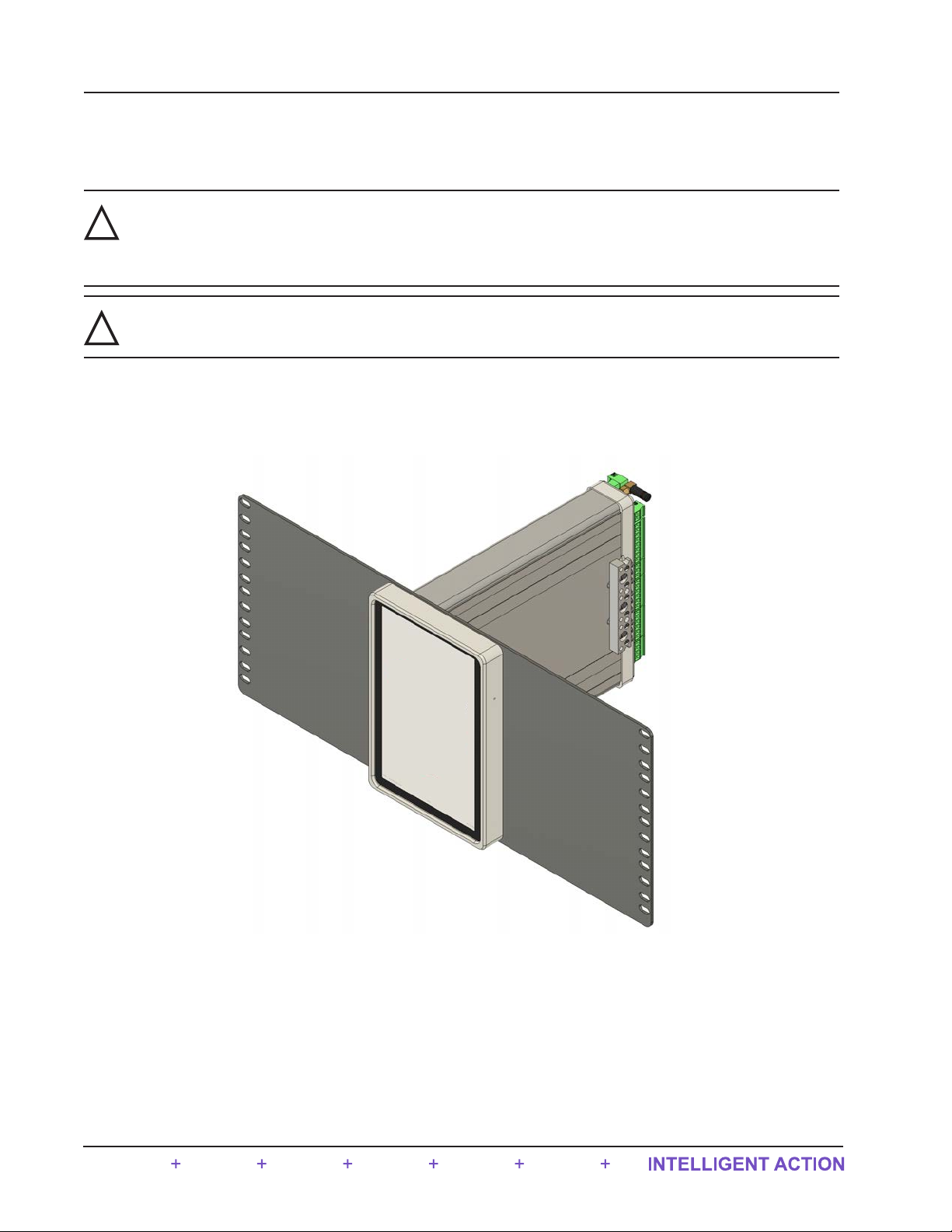
Panel Mounting Kit
It is recommended that the QRATE Scanner 3300 is panel mounted (Figure 1.3). For installation instructions, see Panel
Mounting the QRATE Scanner 3300, page 22.
Figure 1.3 - QRATE Scanner 3300 panel mounted
4
Section 1 QRATE Scanner 3300 integrated control flow computer

Wireless Communications
The QRATE Scanner 3300 wireless communications option includes a factory-installed SmartMesh wireless radio mod-
ule (Figure 1.4).
External SmartMesh Antenna
The Sensia-supplied SmartMesh antenna (Figure 1.4) connects directly to the device side antenna connection. When in-
stalling the antenna, ensure that it is in a vertical position well above ground level and positioned away from large struc-
tures that could interfere with signal transmission and reception.
Sensia’s direct-mount antenna is rated for a maximum of 1 watt of power and a maximum antenna gain of 1.6 dB (in
North America) and has a frequency range of 2.35 to 2.60 GHz. Antennas with equivalent ratings may also be used with
the coupler.
Wi-Fi Antenna
SmartMesh Antenna
(optional)
Figure 1.4 - Standard WiFi antenna and optional SmartMesh antenna
5
QRATE Scanner 3300 integrated control flow computer Section 1
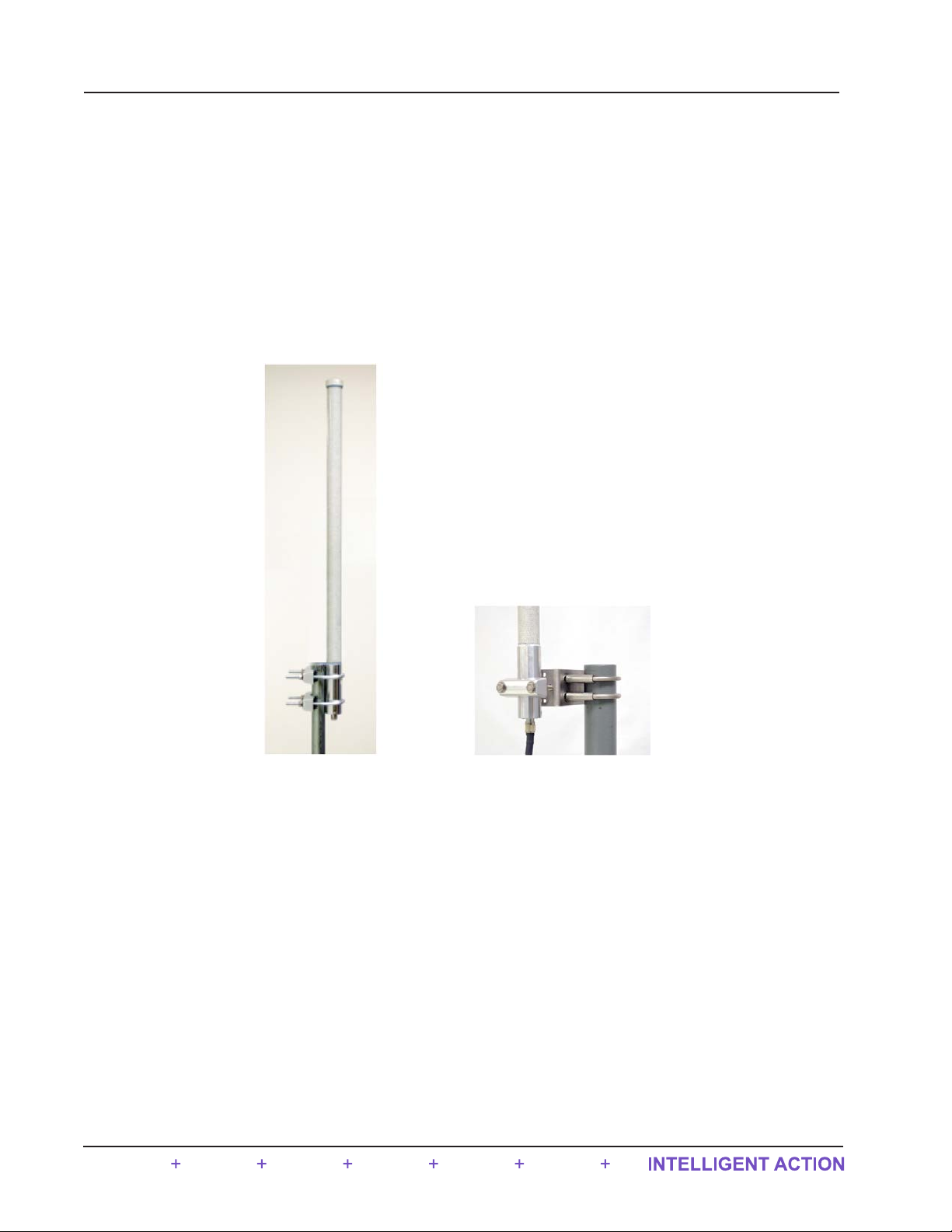
Remote-Mount Antenna
In locations where a physical barrier restricts the use of a direct-mount antenna or where a longer transmission distance
is required, a remote-mount antenna (Figure 1.5) may be installed up to 30 ft (10 m) away and connected by cable to the
antenna coupler. A remote-mount antenna and connecting cable may be purchased from Sensia (see Section 6 - QRATE
Scanner 3300 Parts, page 73). If purchasing cable elsewhere, verify that the cable meets the maximum capacitance and
inductance ratings (Figure 2.7, page 25) and that the cable length is adequate to connect to both the antenna and the
coupler. See Specications, page 8 for additional details.
The installation of the antenna coupler, antennas, and antenna cable must meet the requirements shown in Figure 2.7,
page 25. For installation instructions, see:
• Remote-Mount Antenna for Pole Outside Diameters up to 2 Inches, page 27
• Remote-Mount Antenna for Pipe Outside Diameters of 2 3/8 Inches, page 28
Mounting hardware supplied with
the Sensia remote-mount antenna
(fits pole outside diameters up to 2 inches)
Optional hardware kit for mounting the
Sensia remote-mount antenna to a
2-in. pipe (fits outside diameter of 2 3/8-in.)
Figure 1.5 - Remote-mount antenna mounting options
6
Section 1 QRATE Scanner 3300 integrated control flow computer
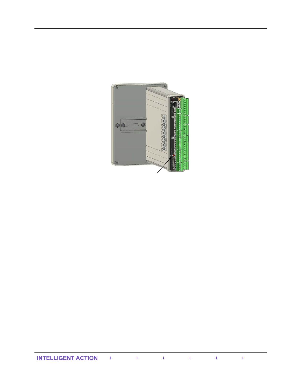
Conguration Lock
The conguration lock is located on the terminal board of the QRATE Scanner 3300 (Figure 1.6). The switch can be
enabled to prevent unauthorized individuals from changing the conguration. By default, this conguration lock fea-
ture is disabled and the switch position is ignored. The conguration lock feature must be enabled via the ADMINIS-
TRATION>GENERAL>SECURITY page of the QRATE Scanner 3300 Web Interface. For more information, see the
QRATE Scanner 3300 Web Interface User Manual. After a device is fully congured, the lock can be enabled by chang-
ing the mechanical switch to the active position and enabling the switch in the web interface security settings.
Configuration
Lock Switch
Figure 1.6 - Conguration lock switch
7
QRATE Scanner 3300 integrated control flow computer Section 1

Specications
Table 1.1—General Specications
Approvals CSA (US and Canada) ordinary location
Environmental
Safety
Relative humidity: 0% to 95% non-condensing
Altitude: Up to 2000 meters
Enclosure Dimensions (L x W x H): 11.2” x 5.4” x 7.8”
Weight 4 lb (1.88 kg), approximate
System Power External user-supplied power supply (9 to 30 VDC, 400 mA min. current rating)
Power over Ethernet (PoE) supply (44 to 57 VDC, 350 mA)
Note: PoE Class 0 is available for non-certied products. Contact the factory for details.
Real-time Clock Accurate within 2 minutes/year over temperature range
Lithium coin cell battery maintains clock during loss of system power (lithium content: 0.11 g)
Processor 32-bit dual-core ARM Cortex M4 + Co-Processor M4
Operating
Temperature –10 °C to 60 °C (14 °F to 140 °F)
Advanced Touch
Display
8.0 in. with 1200 x 1920 resolution
Backlight is 1.4W
Displays up to 32 user-dened parameters (ve at a time), with auto-scrolling
External power indicator
Wireless communications indicator
Parameter status indicators
Congurable background (dark or light) and scroll frequency
Touch screen used for advancing the display; simulating LCD and additional data; connecting
to the web interface; viewing communication settings, serial number, and rmware version;
and restoring factory default settings to the device
Memory 8.18 MB RAM for processing
512 KB non-volatile memory for conguration data
64+1 MB on-board system ash memory
48 MB on-board archive ash memory
Supported
Meter Types
Turbine meter
Cone meter
Orice meter
Ultrasonic meter
Positive displacement (PD) meter
Coriolis meter
Venturi meter
Download Types Per Device Complete (all records, including slave device records as applicable)
Local (integral ow records in a condensed le ideal for emailing)
Events
Triggered (one-second logs, including PID tuning)
Per Flow Run Daily
Interval (hourly)
Event
Recent (past 7 days of interval logs)
Per Slave Daily
Interval (hourly)
Recent (past 7 days of interval logs)
8
Section 1 QRATE Scanner 3300 integrated control flow computer

Table 1.1—General Specications
Archive
Capacity
Up to 58 archivable parameters per ow run
Daily log capacity 2,048 days
Interval log
capacity 2.8 years with 13 parameters (plus date, time and status) logged hourly
Capacity varies with the number of parameters logged (13 to 58) and
logging frequency (1 second to 12 hours)
Triggered log
capacity
(1 to 19
parameters)
1,351,680 logs with one parameter logged;
135,168 logs with 19 parameters logged
Congurable to log periodically (1 second to 12 hours) on a real-time
period (daily, weekly, etc.) on device alarm, on digital input, or when
activated remotely via the web browser
Event Record
Archives Event/Alarm Record Capacity: 81,920 records
User Change Records Capacity: 81,920 records
* Stored in a FLASH non-volatile memory with employs a 16 kB page
erase system (at least one page is partially erased with new entries).
Downloadable via FTP, HTTP (web interface), or Enron Modbus protocol (see Scanner Data
Manager User Manual for information on viewing data les)
Logs stored in non-volatile memory for up to 10 years
Communications/
Archive Retrieval Wireless WiFi radio module available with right-angle antenna. WiFi and Ethernet
together support up to two TCP/IP user-congurable ports with
selectable slave protocols.
WiFi Range is 50 m.
Optional SmartMesh radio module available with or without external
antenna. See Table 1.2—Hardware Options, page 13.
Wired RS-485 Two dedicated ports (1 and 2) and one shared RS-485/RS-232 port (3)
Software-selectable 120-Ω termination resistor
Selectable master and slave protocols (Enron Modbus, Modbus RTU,
Modbus TCP)
Wired RS-232 Shared RS-485/RS-232 port (port 3)
TXD, RXD, RTS, CTS
Time-of-day digital output conguration
Ethernet/TCP One RJ-45 connection. WiFi and Ethernet together support up to two
TCP/IP user-congurable ports with selectable slave protocols.
Continuous use requires external power.
Supports 10/100 Mbits/second
Port Pass-Through Any communications port can be routed to another port
Ethernet can be bridged to serial communications for remotely
interfacing with connected Modbus devices. (For example, a NUFLO
Scanner 2000 series ow computers congured as a slave device using
ModWorX* Pro software without changing wiring connections.)
Flow Rate
Calculations Natural Gas AGA 3 (1992 and 2012), ISO 5167-2 (2003), ISO 5176-5, ASME MFC-
14M (2003), AGA-7 (includes scope of AGA 11)
Liquids API MPMS 5.3, AGA 3, ISO 5167, AGA 7
Fluid Property
Calculations Natural Gas AGA-8 part 1&2 (includes scope of AGA 10), AGA-3, AGA-5, GPA
2145-09, IF-97, ISO 6976
Liquids API MPMS Chapter 11.1 (2004)
Pure Substances IAPWS-IF97 (Steam) Quality-corrected saturated steam (Regions 4)
IAPWS-IF97 (Steam-Water) Auto-selected Region saturated steam,
water, dry steam, critical range (Regions 1 through 4)
9
QRATE Scanner 3300 integrated control flow computer Section 1

Table 1.1—General Specications
Liquid
Compensation and
Correction Factors
Temperature and pressure compensation
Meter factor compensation
Shrinkage factor compensation
Live BS&W correction
Live density correction
Dynamic oil fraction (watercut)—derived from owing density or watercut analyzer; automatic
base density updates from owing density measurement
Chisholm-Steven orice meter multiphase correction for steam
Chisholm-Steven cone meter multiphase correction for steam
Flow Streams Two integral compensated ow run inputs
Up to 20 remote ow runs via NUFLO Scanner 2000 series ow computers in local area
Scanner network
Three additional integral uncompensated pulse/frequency inputs
Bidirectional ow measurement
Up to 8 gas streams using gas chromatograph inputs or user-entered static compositions
16-point calibrations for all inputs (linear factory and multipoint meter factor calibrations also
supported); see Table 1.6—Flow Correction Factors, page 18 for information on multipoint
meter factor calibration
Stacked differential pressure and static pressure inputs for rangeability
RTD Inputs 2 channels
100-Ω platinum RTD with 2-wire, 3-wire, or 4-wire interface
Range: –40 °C to 427 °C (–40 °F to 800 °F), excluding RTD uncertainty
Accuracy: ± 0.2 °C (0.36 °F) over sensing range at calibrated temperature
Temperature effect: ± 0.3 °C (0.54 °F) over operating range
A/D resolution: 24 bits
Sample rate: 0.1 seconds to 12 hours
Congurable shutoff for power savings when transducer warm-up period is not required
Analog Inputs 4 channels and 3 additional channels (current measurement only) congurable through Pulse/
Frequency Inputs
1 to 5 V, 0 to 5 V, 4 to 20 mA, or 0 to 20 mA (AN IN 5,6,7 are 4 to 20 mA or 0 to 20 mA only)
Accuracy: ± 0.030% of span maximum error at 25 °C (77 °F)
Temperature effect: ± 0.25% of span over operating range
Impedance: > 60 kΩ for 1 to 5 V input; approximately 250 Ω for 4 to 20 mA input
Transmitter voltage supply is congurable: 8.5 V to 24 V
Over-voltage protection: 30 VDC
A/D resolution: 22 bits (minimum 20 effective bits)
Linearity error: ± 0.020% max.; ± 0.010% typical
Single-ended inputs
Sample rate: 0.1 seconds to 12 hours
Four previous calibrations available stored in device
Congurable shutoff for saving power when transducer warm-up period is not required
10
Section 1 QRATE Scanner 3300 integrated control flow computer

Table 1.1—General Specications
Pulse/Frequency
Inputs 3 channels (congurable as either Pulse/Frequency Inputs or as Analog Inputs for current)
Maximum voltage: 30 VDC
Maximum frequency: 10,000 Hz
Gated transmitter power for each input channel
Transmitter voltage supply is congurable: 8.5 V to 24 V
Accumulation types: uncompensated gas volume, uncompensated liquid volume, mass
Volume: pulse represents discrete units of volume from a turbine, PD, Venturi, Coriolis, or
ultrasonic meter
Mass: pulse represents discrete units of mass from a Coriolis meter
Congurable turbine sensitivity (20, 50, 100 mV, peak-to-peak)
Analog Outputs 2 channels, channel 1 supports HART communication (Future)
Type 4 to 20 mA, galvanically isolated, externally powered
Accuracy (after calibration): ± 0.1% of span maximum error at 25 °C (77 °F)
Temperature drift: ±50 ppm/°C (±27.8 ppm/°F)
Maximum output load resistance (Ωs) = {supply (volts) – 8.0} / 0.02
Maximum voltage: 30 VDC
D/A resolution: 16 bits
Calibration (zero and full-scale) via software
Programmable output alarm value for use during loss of power or communication to CPU
Regulates control valve in PID control applications
Congurable to track any value including PID Control applications
Digital I/O 6 channels, user-congurable as input or output, and two channels that are output only.
DIO1, DIO2, DIO3, and DIO4 are galvanically isolated with a max. output of 60 mA at 30 VDC
DIO5 and DIO6 are high-speed and non-isolated with a max. output of 500 mA at 30 VDC
Input Types Control switch
Pulse
Open collector
Contact closure
Special Functions Advance display
Turn SmartMesh on/off
Reset specic ow run total
Reset specic pulse input total
Unlatch specic digital inputs/output
Acknowledge alarms
Start or refresh WiFi
Publish triggered archive record
Release triggered archive latch
Create partial archive
Abort script program
Reset script program
11
QRATE Scanner 3300 integrated control flow computer Section 1

Table 1.1—General Specications
Digital I/O
(cont’d) Output Modes Pulse (based on pulse count or time period)
Alarm (based on the status of any or all selected alarms; up to 32 user-
congured alarms are selectable)
Conditional (value above or below setpoint, out of setpoint range)
Programmed [time of day or output state (normally open, normally
closed)]
Congurable to track any value including PID Control applications
POUT1 and POUT2 mirror DO 5 and 6
Pulse Output Maximum frequency: 500 Hz
Congurable pulse duration (10 msec to 1 day)
Congurable pulse representation (1 pulse = 1 MCF) based on time or
volume
Based on any accumulator (ow run or turbine meter run)
Alarm Output Low/high
Out-of-range
Status/diagnostic
Web Interface—
Local Device
Management
Access data and device settings via the advanced display on the front of the device
Congure, calibrate, and maintain ow runs, inputs/outputs, and gas streams
Poll real-time data
Download data
View daily logs and up to 7 days of interval (recent) logs
Control user access with four levels of security
Congure communications with up to 20 wired or wireless NUFLO Scanner 2000 series ow
computers
Display real-time data, ow rate calculation method, and input averages for up to 20 slave
devices
Read and store conguration data from up to 20 slave devices
Read and store daily and interval archive records for up to 20 slave devices
Change gas composition and plate size in slave device congurations
Download slave data via FTP, HTTP, or Enron Modbus protocol
Synchronize slave device conguration and slave archive data
Read gas streams connected to slave devices
Clear slave device grand totals and alarms
Load factory default conguration le
Remotely reset slave device without cycling power
12
Section 1 QRATE Scanner 3300 integrated control flow computer

Table 1.2—Hardware Options
Wireless
SmartMesh Radio 2.4 GHz self-healing and self-sustaining network
Factory installed antenna coupler with 12-in. coaxial cable and MMCX male connector
Transmits up to 300 m (985 ft) node-to-node
Radio Certications Supports communications with up to 20 remote NUFLO Scanner 2000 series ow computers
(each Scanner node can transmit and receive data)
Radio certications (by country):
Europe: CE Mark, RED
North America: FCC/IC
Antenna Direct-Mount Remote-Mount
Electrical Properties
Frequency Range 2.35 to 2.60 GHz 2.4 to 2.5 GHz
Impedance 50 Ωs nominal at 2.45 GHz 50 Ωs nominal at 2.4 GHz
Voltage Standing Wave
Range (VSWR) ≤ 2.0 typical at center <1.5
Connector SMA N female brass nickel-plated
connector, cable required for
connection to SMA
Height 25.6 mm (1.01 in.) 800 mm (32.28 in.)
Shape Elbow (right angle) Straight
Material Weatherized plastic Fiberglass
Operating Temperature –40 °C to 90 °C (–40 °F to
194 °F) –40 °C to 80 °C (–40 °F to
176 °F)
Pole Mount Hardware
—N/A Standard hardware (included
with antenna) ts pole with
outside diameter up to 2 in.
—N/A Alternate remote-mount kit
available for pipe with outside
diameter of 2 3/8 in.
Antenna Cable Length N/A 10-, 20-, and 30-ft with
connectors
Type N/A Type 400
Temperature Range N/A –40 °C to 70 °C (–40 °F to
158 °F)
Customer Tag Stainless steel tag for customer-specied information, 3 in. × 3 in., wired on, 5 lines of text, 45
character per line maximum
13
QRATE Scanner 3300 integrated control flow computer Section 1

Table 1.3—Scanner Companion Software
Important To download software or software user manuals, visit the Sensia website at
https://www.sensiaglobal.com/Measurement/Types/Flow-Computing-and-Automation, select QRATE
Scanner 3000 series integrated control ow computers, and click on the link for the desired
software install/manual.
Scanner Logic
IDE Creates Scanner Logic scripts (SLOGIC) and compiles them into a logic-controller program le
(SLBIN).
Performs live debugging on scripts, showing immediate and upcoming script sections to be
debugged.
Uses a high-level procedural programming language designed to build logic controllers. In this way,
the program resembles a state machine.
Scanner Data
Manager Opens proprietary data les (.sdf) downloaded from the QRATE Scanner 3300 and provides tools for
data analysis, reporting, export and conversion
Presents data in tabular and trend views
Includes tools for customizing reports
ScanMap Creates custom QRATE Scanner 3300 Modbus register maps, including user-specied units, rates,
and register names for SCADA integration
Firmware-specic templates
Auto-generates protocol manual for printing or uploading to the web interface
ScanFlash Uploads rmware (BIN), conguration (SRF), Scanner Logic IDE le (SLBIN), and custom Modbus
register map (PMAP) les to the QRATE Scanner 3300
PC Requirements
Windows 7 or later operating system
1 GHz or faster 32-bit (x86) or 64-bit (x64) processor
1 GB RAM (32-bit) or 2 GB RAM (64-bit) available hard disk space (360 MB for companion software installation, 30
MB for software for PDF reading, adequate space for data les)
DirectX 9 graphics device with WDDM 1.0 or later driver
Flow Rate and Fluid Property Calculations
The QRATE Scanner 3300 calculates ow rates and uid properties for natural gas and liquid ow in accordance with
the following industry standards. The calculations compensate for the effects of pressure, temperature, and uid compo-
sition to determine mass and volume at specied base conditions. The uid corrections typically require conguration of
inputs including static pressure and temperature. The ow calculation requires conguration of differential pressure or
pulse (frequency) inputs.
14
Section 1 QRATE Scanner 3300 integrated control flow computer
Table of contents
Popular Desktop manuals by other brands


Lenovo
Lenovo 6072CC3 - Thinkcentre M57 2.33G2gb 80Gb Dvdrom... Hardware installation and replacement guide

Lenovo
Lenovo ThinkCentre E73 Hardware Maintenance Manual

Lenovo
Lenovo ThinkCentre Safety and Warranty Guide

Lenovo
Lenovo ThinkCentre1562 user guide

Zotac
Zotac ZBOX Inspire Studio quick start guide

Aaeon
Aaeon AIS-Q454 manual