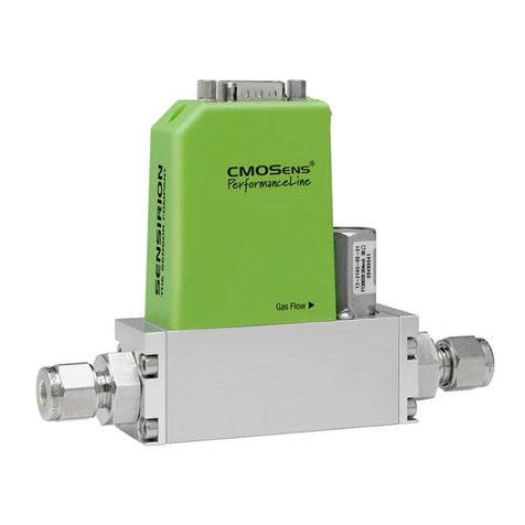
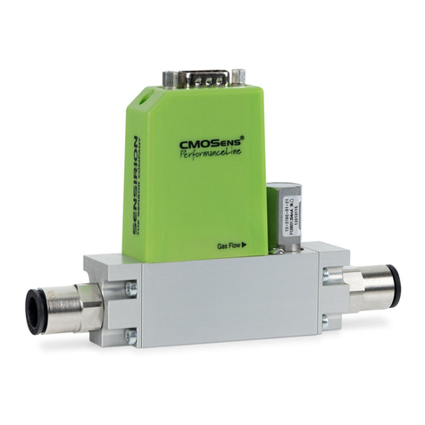
SENSIRION SFC6 Series User manual

www.sensirion.com
Version 1 –Mar 2023
1 / 13
Copyright © Sensirion AG 2022.
Engineering guidelines for Mass Flow Controllers
(SFC6xxx) and Mass Flow Meters (SFM6xxx)
Summary
This guide provides recommendations for evaluation, testing and integration of Sensirion Mass Flow Controllers and
Meters. It is applicable to SFC6xxx as well as SFM6xxx products.
For clarity, the document was written for Mass Flow Controllers, yet most guidelines are also valid for Mass Flow Meters.

www.sensirion.com
Version 1 –Mar 2023
2 / 13
Copyright © Sensirion AG 2022.
Contents
1. How to choose your Mass Flow Controller (Mass Flow Meter)........................................................................................................... 3
1.1. Flow Selection for SFC6000(D)/SFM6000(D)............................................................................................................................. 3
2. How to operate your Mass Flow Controller................................................................................................................................................. 3
2.1. Digital interface ..................................................................................................................................................................................... 3
2.2. Analog interface: Coming Soon ..................................................................................................................................................... 4
3. Testing recommendations................................................................................................................................................................................... 5
4. Common pitfalls ...................................................................................................................................................................................................... 5
4.1. Flow appears to be off by several %............................................................................................................................................. 5
4.2. Settling time is longer than specified .......................................................................................................................................... 5
5. Design recommendations ................................................................................................................................................................................... 5
5.1. The effect of orientation and temperature on accuracy ...................................................................................................... 5
5.2. The effect of vibrations on valve function.................................................................................................................................. 6
5.3. Pressure drop and input pressure ................................................................................................................................................. 6
6. Fluidic and electrical connectors ...................................................................................................................................................................... 7
6.1. Mounting guide .................................................................................................................................................................................... 7
6.1.1. Mounting from the bottom of device ................................................................................................................... 7
6.1.2. Mounting from the bottom of device ................................................................................................................... 7
6.1.3. Downmount manifold .................................................................................................................................................. 8
7. Useful resources ...................................................................................................................................................................................................... 9
7.1. Documentation...................................................................................................................................................................................... 9
7.2. CAD models..........................................................................................................................................................................................12
7.3. Software tools......................................................................................................................................................................................12
7.3.1. Control Center software ............................................................................................................................................12
7.3.2. Software drivers ............................................................................................................................................................12
7.4. Calibration and FAQ ..........................................................................................................................................................................12

www.sensirion.com
Version 1 –Mar 2023
3 / 13
Copyright © Sensirion AG 2022.
1. How to choose your Mass Flow Controller (Mass Flow Meter)
Sensirion offers several families of Mass Flow Controllers and Meters. The following covers the 6000 series family.
•SFC6000 (SFM6000) family offers the best price to performance ratio for a mass flow controller in a compact and
lightweight package and is fully customisable to your needs. Minimum order quantities apply when purchasing
from Sensirion.
•SFC6000D (SFM6000D) are SFC6000 mass flow controllers and SFM6000 mass flow meters available in fixed
configurations with pre-configured multiple gas calibrations, different flow ranges and exchangeable fittings
available via distribution.
To help you choose the right Mass Flow Controller, a “Selection guide”is available on the Sensirion website. Please see
the useful resources section below.
1.1. Flow Selection for SFC6000(D)/SFM6000(D)
The Sensirion SFC6000 flow controllers and SFM6000 flow meteres are available for full flow rates from 0.5 slm to 50 slm.
SFC6000D and SFM6000D are available at different flow ranges, shown in Table 1, to suit your application best.
Product
Variant
Flow Range
SFC6000D-/SFM6000D-
5 slm
5 slm –0 slm
20 slm
20 slm –0 slm
50 slm
50 slm –0 slm
Table 1. Flow ranges of the respective product variants of SFC6000D and SFM6000D
2. How to operate your Mass Flow Controller
The evaluation method depends on whether your Mass Flow Controller has a digital or an analog interface.
2.1. Digital interface
There are several ways to operate Sensirion digital Mass Flow Controllers exist. They vary in complexity and implementation
flexibilities.
•The EK-F5x evaluation kit together with Sensirion Control Center is the fastest way to start working with your
device. It is a plug-and-play solution, which will enable you to control and configure your device (e.g. choose the
gas calibration). The EK-F5x evaluation kit combines a power supply (adapters for most sockets worldwide are
included) and a USB-A plug for your PC. It connects to your device with a M8 or DB9 plug (an adapter is available
for other plugs –please contact Sensirion). EK-F5x is available from distribution. Please note, Mass Flow Controller
or Flow Meter are not included and must be purchased separately.
•Most OEM projects will require designing custom cabling (including a power supply) together with an
implementation in the desired programming language. The SFC6000 provides an I2C and a RS-485 interface (the
respective guides are found in Section 7.1 in Useful Resources). Sensirion provides ready-to-use libraries in C and
Python, as illustrated in Table 2. These libraries can be used to control multiple devices at the same time (please
make sure the devices have unique SHDLC and I2C addresses for RS-485 and I2C interfaces, respectively). However,
this also involves the highest implementation effort out of the options mentioned here.

www.sensirion.com
Version 1 –Mar 2023
4 / 13
Copyright © Sensirion AG 2022.
Quick, plug-and-play
Simple implementation and flexibility
MFC
MFC
EK-F5x
Evaluation Kit
Sensirion
Control Center
EK-F5x
Evaluation Kit
Sensirion C / Python library
RS-485: Custom design with full implementation flexibility
I2C: Custom design with full implementation flexibility: Coming Soon
MFC
MFC
Custom cabling and external power
supply
Sensirion C / Python library
Custom cabling and external power
supply
Sensirion C library
Figure 1. Overview of different options for evaluating digital Mass Flow Controllers and Mass Flow Meters
The following illustrates the available software drivers for respective PC interfaces for the SFC6000 and SFM6000 variants.
PC interface
Python driver
C driver
Sensirion Control
Center
USB (EK-F5x
Evaluation kit)
Available
Available
(For Raspberry pi)
Available
RS-485
Under Development
Available (Arduino
shield)
-
I2C
-
Under Development
(For Arduino)
-
Table 2. The available drivers for different modes of communication for the SFC6000 and SFM6000. Links to the software
can be found in the software tools section below.
2.2. Analog interface
The analog output pin gives out an analog linear voltage representing the flow value in standard liter per minute
(slm). The formula for converting the voltage value to slm is given by:
i.e. the analog voltage range from 0.5 V to 4.5 V is linearly mapped to the flow range of 0 slm to full scale flow slm. The
identical conversion formula applies for the analog input voltage.

www.sensirion.com
Version 1 –Mar 2023
5 / 13
Copyright © Sensirion AG 2022.
3. Testing recommendations
It is recommended to start by testing the communication with the device, using the EK-F5x Evaluation Kit and Control
Center.
As a second step, connect the device to a gas supply (or a source of vacuum). For better accuracy, mount the Mass Flow
Controller horizontally and use the same pressure as during factory-calibration (specified in the datasheet, by default for
most products 3 bar inlet vs outlet).
Try using different setpoint steps to test the Mass Flow Controller. If the chosen setpoint can’t be reached, try increasing
the supply pressure, removing fluidic resistances like filters, or using tubes with a larger diameter. If the supply pressure
used is significantly lower than the calibration pressure, the controller can be slower than expected. On the other hand, if
the supply pressure is significantly larger than the calibration pressure, the Mass Flow Controller may become unstable. In
these cases, lowering or increasing the controller gain to adapt the controller accordingly. This can be done conveniently
with Sensirion Control Center. For detailed instructions, see the “Control Center manual”, linked in “Useful resources”
Section 7.3.1.
4. Common pitfalls
4.1. Flow appears to be off by several %
If the flow appears to be off by several % (especially around 7%) against your reference, there are good chances the flow
units of the two devices are not the same. The conversion difference between standard litres and norm litres is around 7%,
due to the different reference temperatures used for standard and norm litres. Please make sure that the Mass Flow
Controller and your reference are using the same units when testing. Further information about the flow unit conversion
can be found in a dedicated application note, “Reference and Flow Conversions between mass and volumetric flow”, in the
“Useful resources” Section 7.1.
4.2. Settling time is longer than specified
The most common cause for observing longer than expected settling time is trying to verify it from a position of fully closed
valve. Solenoid valves are commonly affected by so-called “sticking effect”. To open the valve from closed position (setpoint
0), a certain overvoltage is required to overcome the stiction effect. This can lead to a spike in the flow (especially for low
setpoints) or a longer than expected settling time. By adjusting the “Initstep” or “Controller gain” of the Mass Flow
Controller, the behaviour can be tuned to the specific requirements.
The settling time of Sensirion’s Mass Flow Controllers is specified for a step answer from 10% to 100% of full scale within
5% of setpoint. When starting from zero flow the settling time may be longer than specification.
5. Design recommendations
5.1. The effect of orientation and temperature on accuracy
To achieve best accuracy, it is recommended to use a design where the Mass Flow Controller is mounted horizontally.
The operation of the valve produces a significant amount of heat. The Mass Flow Controller should therefore not be placed
in a hermetically sealed space. It is recommended to design a cooling flow over the Mass Flow Controller in order to
counteract the heating from the valve. Large temperature gradient between the Mass Flow Controller and the gas it is used
to control, may adversely influence the accuracy of the device.

www.sensirion.com
Version 1 –Mar 2023
6 / 13
Copyright © Sensirion AG 2022.
5.2. The effect of vibrations on valve function
The valve used in the Mass Flow Controllers (proportional valve) is an oscillating system. Try to avoid sources of vibrations
or decouple these sources mechanically from the Mass Flow Controller. They can interfere with the proper function of the
valve.
5.3. Pressure drop, temperature and input pressure
Pressure drop is generated when gas passes through the valve of a mass flow controller. The magnitude of the pressure
drop is proportional to the flow rate and the density of the gas. Additionally, the maximum flow rate can be affected by
temperature. The magnetization of the valve decreases with a higher valve temperature caused by continuous operation
or high ambient temperature. The maximum flow decreases, as the valve is less open.
It is important to verify that at the maximum required flow rate, for a given gas, the inlet pressure is higher than the pressure
drop. If this cannot be achieved, contact Sensirion –it might be possible to order a similar mass flow controller with larger-
sized valve. Larger valves offer a lower pressure drop at the cost of a decreased accuracy/resolution at low flows.

www.sensirion.com
Version 1 –Mar 2023
7 / 13
Copyright © Sensirion AG 2022.
6. Fluidic and electrical connectors
Product reference
Fluidic connector
Electrical
connector
SFC6000D/
SFM6000D
Push-in: tube outer diameter 6 mm, Downmount
(exchangeable with Festo QSP 18 mm interface)
M8 (4 pin)
Table 3. Fluidic and electrical connectors
6.1. Mounting guide
The SFC6000 can be mounted from the bottom, the top or on a downmount manifold depending on application
requirements. A more comprehensive description of the mounting options is coming soon.
6.1.1. Mounting from the bottom of device
With the help of tapping screws (PT-screw K30, diameter = 3mm) the devices can be secured on the plate from the bottom.
One should not screw the tapping screws more than 8 mm into the body of the device. Do not use larger screws, as this
introduces stress to the device, influencing performance.
6.1.2. Mounting from the top of device
The SFC6000 and SFM6000 can also be mounted from the top when removing their cap. This is done with M2.5 X 20 screws.

www.sensirion.com
Version 1 –Mar 2023
8 / 13
Copyright © Sensirion AG 2022.
6.1.3. Downmount manifold
Downmount connectors are included with each distribution SFC6000D and SFM6000D.
Figure 2. Dowmount fittings on SFM6000(D) (left) and SFC6000(D) (right).
When using products with downmount connectors, a specific manifold must be designed and manufactured by the user.
In Table 4in the useful resources section, CAD models for a suggested manifold designs for SFC6000(D) / SFM6000(D) can
be found. They can be used as a starting point for a custom design.
4 screws can be used for mounting. The O-rings must be placed on the Mass Flow Controller side. The manifold pictured
below can be used as a starting point for the design. A mass Flow Controller is placed on top of the manifold.
Figure 3. Downmount manifold design for SFM6000(D) (left) and SFC6000(D) (right).

www.sensirion.com
Version 1 –Mar 2023
9 / 13
Copyright © Sensirion AG 2022.
7. Useful resources
7.1. Documentation
Various guides and application notes are available on Sensirion website.
Mass Flow Controllers (SFC): Product catalog (sensirion.com)
Mass Flow Meters (SFM): Product catalog (sensirion.com)
General technical download section: sensirion.com/products/downloads/
The most relevant resources are linked below.
Datasheet
Selection Guide
Quick start guide
SFC6000 gas fittings guide

www.sensirion.com
Version 1 –Mar 2023
12 / 13
Copyright © Sensirion AG 2022.
7.2. CAD models
Product
CAD model
Link
SFC6000D/
SFM6000D
Push in with green cap,
Downmount with green cap,
Downmount manifold
https://sensirion.com/resource/cad/sfc-sfm6000
Table 4. SFC6000D and SFM6000D and downmount manifold CAD models.
7.3. Software tools
7.3.1. Control Center software
Sensiron Control Center and manual
https://sensirion.com/products/sensor-evaluation/control-center/
7.3.2. Software drivers
Python driver (For use with EK-F5x evaluation kit or custom cabling)
https://github.com/Sensirion/python-uart-sfx6xxx
C driver (For use with Raspberry-Pi)
https://github.com/Sensirion/raspberry-pi-uart-sfx6xxx
Arduino Library
https://github.com/Sensirion/arduino-uart-sfx6xxx
7.4. Calibration and FAQ
Thanks to the stability of the MEMS-based sensor element and the robust mechanical design, Sensirion Mass Flow
Controllers do not drift and do not require recalibration in the field.
High manufacturing standards used during production ensure that our Mass Flow Controllers are extremely reliable and
have a very low failure rate. This is supported by field surveys and measurements.
FAQ:
sensirion.com/products/support/faq/

www.sensirion.com
Version 1 –Mar 2023
13 / 13
Copyright © Sensirion AG 2022.
Important Notices
Warning, Personal Injury
Do not use this product as safety or emergency stop devices or in any other application where failure of the product could result in
personal injury. Do not use this product for applications other than its intended and authorized use. Before installing, handling, using
or servicing this product, please consult the data sheet and application notes. Failure to comply with these instructions could result in
death or serious injury.
If the Buyer shall purchase or use SENSIRION products for any unintended or unauthorized application, Buyer shall defend, indemnify and
hold harmless SENSIRION and its officers, employees, subsidiaries, affiliates and distributors against all claims, costs, damages and
expenses, and reasonable attorney fees arising out of, directly or indirectly, any claim of personal injury or death associated with such
unintended or unauthorized use, even if SENSIRION shall be allegedly negligent with respect to the design or the manufacture of the
product.
ESD Precautions
The inherent design of this component causes it to be sensitive to electrostatic discharge (ESD). To prevent ESD-induced damage and/or
degradation, take customary and statutory ESD precautions when handling this product.
See application note “ESD, Latch up and EMC” for more information.
Warranty
SENSIRION warrants solely to the original purchaser of this product for a period of 12 months (one year) from the date of delivery that
this product shall be of the quality, material and workmanship defined in SENSIRION’s published specifications of the product. Within such
period, if proven to be defective, SENSIRION shall repair and/or replace this product, in SENSIRION’s discretion, free of charge to the
Buyer, provided that:
•notice in writing describing the defects shall be given to SENSIRION within fourteen (14) days after their appearance;
•such defects shall be found, to SENSIRION’s reasonable satisfaction, to have arisen from SENSIRION’s faulty design, material, or
workmanship;
•the defective product shall be returned to SENSIRION’s factory at the Buyer’s expense; and
•the warranty period for any repaired or replaced product shall be limited to the unexpired portion of the original period.
This warranty does not apply to any equipment which has not been installed and used within the specifications recommended by
SENSIRION for the intended and proper use of the equipment. EXCEPT FOR THE WARRANTIES EXPRESSLY SET FORTH HEREIN, SENSIRION
MAKES NO WARRANTIES, EITHER EXPRESS OR IMPLIED, WITH RESPECT TO THE PRODUCT. ANY AND ALL WARRANTIES, INCLUDING
WITHOUT LIMITATION, WARRANTIES OF MERCHANTABILITY OR FITNESS FOR A PARTICULAR PURPOSE, ARE EXPRESSLY EXCLUDED AND
DECLINED.
SENSIRION is only liable for defects of this product arising under the conditions of operation provided for in the data sheet and proper
use of the goods. SENSIRION explicitly disclaims all warranties, express or implied, for any period during which the goods are operated or
stored not in accordance with the technical specifications.
SENSIRION does not assume any liability arising out of any application or use of any product or circuit and specifically disclaims any and
all liability, including without limitation consequential or incidental damages. All operating parameters, including without limitation
recommended parameters, must be validated for each customer’s applications by customer’s technical experts. Recommended parameters
can and do vary in different applications.
SENSIRION reserves the right, without further notice, (i) to change the product specifications and/or the information in this document and
(ii) to improve reliability, functions and design of this product.
Copyright © 2021, by SENSIRION. CMOSens® is a trademark of Sensirion. All rights reserved
Headquarters and Subsidiaries
Sensirion AG
Laubisruetistr. 50
CH-8712 Staefa ZH
Switzerland
Sensirion Inc., USA
phone: +1 312 690 5858
info-us@sensirion.com
www.sensirion.com
Sensirion Korea Co. Ltd.
phone: +82 31 337 7700~3
info-kr@sensirion.com
www.sensirion.com/kr
phone: +41 44 306 40 00
fax: +41 44 306 40 30
info@sensirion.com
www.sensirion.com
Sensirion Japan Co. Ltd.
phone: +81 3 3444 4940
info-jp@sensirion.com
www.sensirion.com/jp
Sensirion China Co. Ltd.
phone: +86 755 8252 1501
info-cn@sensirion.com
www.sensirion.com/cn
Sensirion Taiwan Co. Ltd
phone: +886 3 5506701
info@sensirion.com
www.sensirion.com
To find your local representative, please visit www.sensirion.com
This manual suits for next models
3
Table of contents
Other SENSIRION Controllers manuals
Popular Controllers manuals by other brands
Rain Bird
Rain Bird ESP-LXIVM troubleshooting guide
Rain Bird
Rain Bird ET Manager Series Installation and operation manual

Hills Reliance
Hills Reliance TouchNav User reference guide
Crouzet
Crouzet 88 970 117 manual
HEIDENHAIN
HEIDENHAIN ND 280 - GUIDE Quick reference guide
Mitsubishi
Mitsubishi FX2NC Series user manual


