manuals.online logo
Brands
  1. Home
  2. •
  3. Brands
  4. •
  5. LEGRAND
  6. •
  7. Controllers
  8. •
  9. LEGRAND 0 766 22 User manual

LEGRAND 0 766 22 User manual

Other LEGRAND Controllers manuals

LEGRAND 784 28 User manual

LEGRAND

LEGRAND 784 28 User manual

LEGRAND Wattstopper LMRC-611MCC User manual

LEGRAND

LEGRAND Wattstopper LMRC-611MCC User manual

LEGRAND 0 648 84L User manual

LEGRAND

LEGRAND 0 648 84L User manual

LEGRAND Arteor User manual

LEGRAND

LEGRAND Arteor User manual

LEGRAND 038 09 Quick start guide

LEGRAND

LEGRAND 038 09 Quick start guide

LEGRAND adorne WNAL33/43 User manual

LEGRAND

LEGRAND adorne WNAL33/43 User manual
LEGRAND 488 43 User manual

LEGRAND

LEGRAND 488 43 User manual

LEGRAND Valena Allure Series User manual

LEGRAND

LEGRAND Valena Allure Series User manual

LEGRAND 0 488 64 User manual

LEGRAND

LEGRAND 0 488 64 User manual

LEGRAND Wattstopper LMRC-611MCC-A User manual

LEGRAND

LEGRAND Wattstopper LMRC-611MCC-A User manual

LEGRAND C2G 29977 User manual

LEGRAND

LEGRAND C2G 29977 User manual

LEGRAND Mosaic 335 25 User manual

LEGRAND

LEGRAND Mosaic 335 25 User manual

LEGRAND HD4657M3 User manual

LEGRAND

LEGRAND HD4657M3 User manual

LEGRAND 0 026 72 User manual

LEGRAND

LEGRAND 0 026 72 User manual

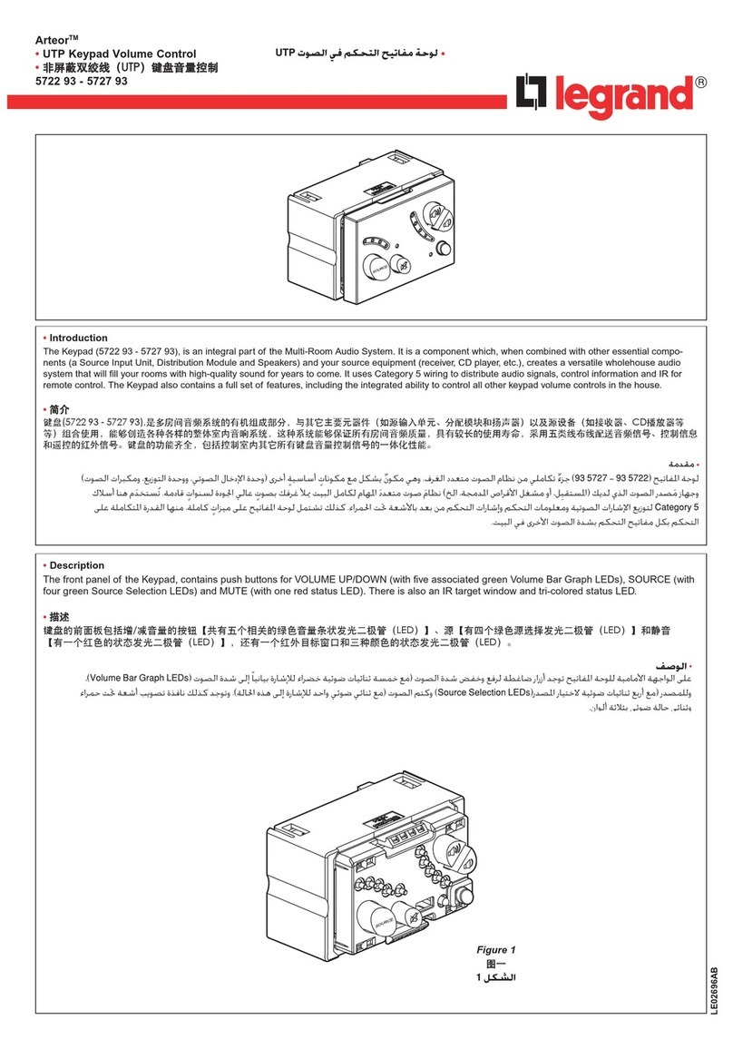
LEGRAND Arteor 5722 93 User manual

LEGRAND

LEGRAND Arteor 5722 93 User manual
LEGRAND Valena Next User manual

LEGRAND

LEGRAND Valena Next User manual

LEGRAND 0 784 48 User manual

LEGRAND

LEGRAND 0 784 48 User manual

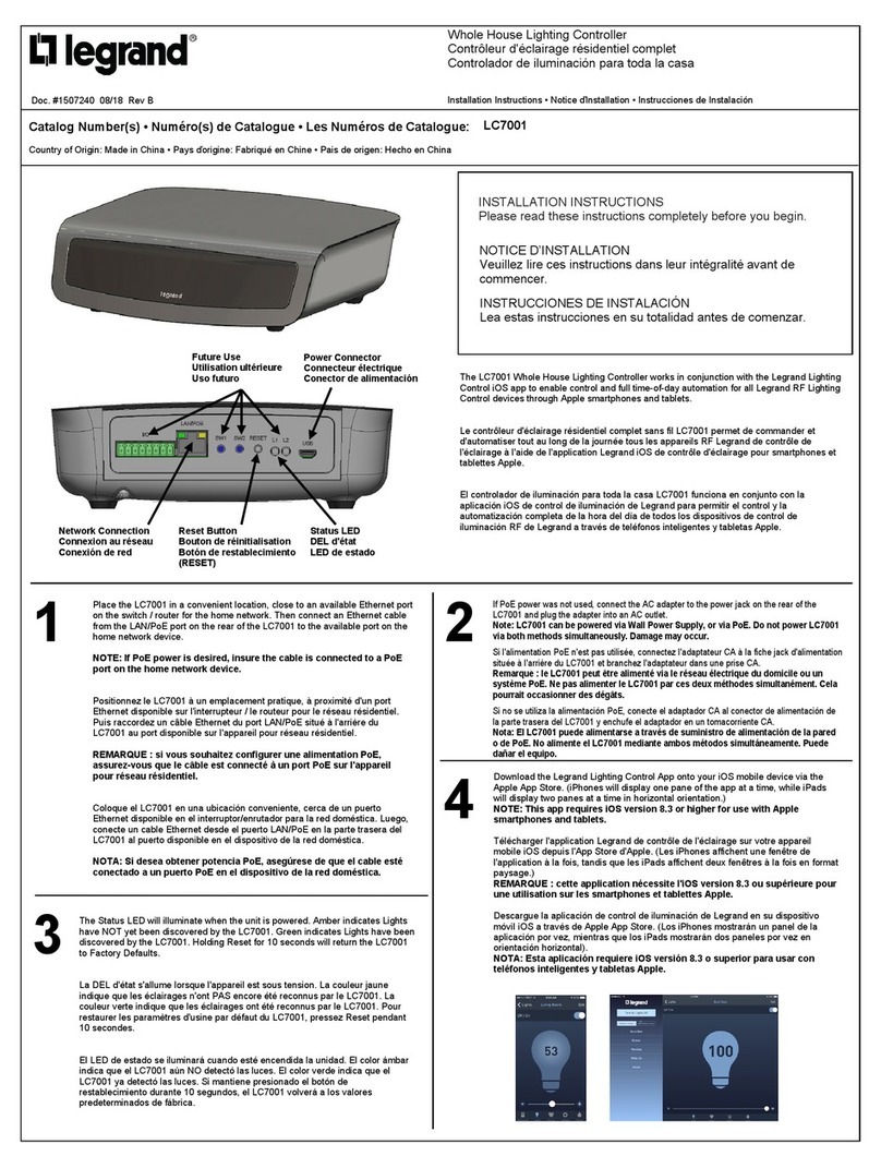
LEGRAND Adorne LC7001 User manual

LEGRAND

LEGRAND Adorne LC7001 User manual

LEGRAND Galion K8/H251-HK User manual

LEGRAND

LEGRAND Galion K8/H251-HK User manual

LEGRAND adorne WZ3ACB40 User manual

LEGRAND

LEGRAND adorne WZ3ACB40 User manual

LEGRAND 0 035 40 User manual

LEGRAND

LEGRAND 0 035 40 User manual

LEGRAND 672 40 User manual

LEGRAND

LEGRAND 672 40 User manual

LEGRAND 3550 User manual

LEGRAND

LEGRAND 3550 User manual

LEGRAND C2G 29977 User manual

LEGRAND

LEGRAND C2G 29977 User manual
Popular Controllers manuals by other brands

Sunricher SR-ZV9003T3-RGBW-US Installation

Sunricher

Sunricher SR-ZV9003T3-RGBW-US Installation

Ksenia intro Installation and configuration manual

Ksenia

Ksenia intro Installation and configuration manual

Inovance CAN200 Series manual

Inovance

Inovance CAN200 Series manual

Gauzy LC6 FLEX Controller Installation and operation guide

Gauzy

Gauzy LC6 FLEX Controller Installation and operation guide

Viking SLP-1 Technical practice

Viking

Viking SLP-1 Technical practice

CKD KBX-30E-U Series instruction manual

CKD

CKD KBX-30E-U Series instruction manual

Sharp Energy Sun Flux User manual & installation guide

Sharp Energy

Sharp Energy Sun Flux User manual & installation guide

Yamaha RCX40 user manual

Yamaha

Yamaha RCX40 user manual

AB Quality PowerFlex 400 Frames D-H Service bulletin

AB Quality

AB Quality PowerFlex 400 Frames D-H Service bulletin

Yamaha MJC8 owner's manual

Yamaha

Yamaha MJC8 owner's manual

AL-KO ATC operating instructions

AL-KO

AL-KO ATC operating instructions

Savant SmartControl 2 Deployment guide

Savant

Savant SmartControl 2 Deployment guide

GameSir T3S user manual

GameSir

GameSir T3S user manual

Kostal inveor operating manual

Kostal

Kostal inveor operating manual

Emerson Yarway 20-55 Operating and safety instructions

Emerson

Emerson Yarway 20-55 Operating and safety instructions

CoCo ACM-LV24 Quick installation guide

CoCo

CoCo ACM-LV24 Quick installation guide

Brooks SLA5810/20 Installation and operation manual

Brooks

Brooks SLA5810/20 Installation and operation manual

SIGMA TEK SR 011 Technical manual

SIGMA TEK

SIGMA TEK SR 011 Technical manual

manuals.online logo
manuals.online logoBrands
  • About & Mission
  • Contact us
  • Privacy Policy
  • Terms and Conditions

Copyright 2025 Manuals.Online. All Rights Reserved.

INSTALLATION AND USER GUIDE
SECURE WANDERING
SYSTEM
4
7
C
1
5
8
0
2
6
9
E
3
2 INSTALLATION PRINCIPLE
2 System description
3 DEVICE PRESENTATION AND
INSTALLATION
3 Secure wandering device
6 Secure wandering system - auxiliary elements
7 STANDALONE INSTALLATION
7 Example of installation
9 Wiring - controllers and antennae
10 Operating modes
11 SYSTEM INSTALLATION
11 Example of installation
13 Wiring - controller/antennae and door unit
14 Operating modes
15 COMMISSIONING
15 Factory settings
16 Settings
18 Adjusting the antennae
19 OPERATION
19 Operation in day mode (surveillance)
20 Operation in night mode (intruder)
21 Illuminated and audible signals
22 CHARACTERISTICS
22 Specifications
23 USAGE CODES
23 Control code
24 CONTROLLER CONFIGURATION
24 Checking the controller parameters
Contents
2
CONTENTS
Functionality
The secure wandering system is a system which allows
any potential escape attempts by confused patients to
be controlled.
Each exit under surveillance is fitted with a standalone
controller which alerts staff when a person wearing
a special wristband tries to go through it. In the event
that there are no supervisory staff near the exit, this
information can be transmitted to the BUS/SCS nurse
call unit using a door unit Cat. No. 0 766 06 configured
for this function. This way nurses are immediately
alerted to the escape and which door they have
gonethrough.
The system can operate using two modes:
• Surveillance mode: An alarm is activated when the
wearer of a wristband is close to the exit and this exit is
open.
• Intruder mode: An alarm is activated when an exit
isopened.
Switching from one mode to the other can be done
manually by entering a special code into the controller
keypad or by closing a clock contact.
The staff have a chaperone code which allows a
wristband wearer to be let through an exit under
surveillance without triggering an alarm.
Two control outputs allow:
• The exit to be locked once a wristband is detected
in the vicinity (provide an electromagnetic lock or an
electric door release).
• An audible or illuminated warning signal to be
triggered when an escape alarm is activated.
Safety instructions
This product must be installed in accordance with the
installation instructions, and preferably by a qualified
electrician. Incorrect installation and use may lead to
the risk of electric shock or fire. Read the manual and
consider exactly where the product is to be fitted before
carrying out installation.
Do not open, remove, alter or modify the device
unless this is specifically stated in the instructions.
Legrand products must only be opened and repaired
by personnel trained and authorised by Legrand.
Any unauthorised opening or repair voids all liability,
replacement rights and warranties.
Only use Legrand brand accessories.
Operating environment
- This device complies with the directives concerning
exposure to radioelectric frequencies when used
under the normal conditions described in the user
manual. Follow the installation instructions described in
themanual.
- Depending on the configuration, this device regularly
transmits radio waves, the frequency and power of
which comply with ARCEP recommendations.
SYSTEM DESCRIPTION
Installation principle
3
CONTENTS
Device presentation and installation
SECURE WANDERING DEVICE
4
7
C
1
5
8
0
2
6
9
E
3
E
6
9
E
3
C
0
0
4
7
1
5
8
2
1
2
7
3
4
5
6
Situated close to the exit door, this controller is the
heart of the system.
All auxiliary elements are connected to it.
A 12-button keypad is used to configure it and
activate special functions (mode changes, alarm
acknowledgement, etc).
Buzzer and LEDs act as a warning if an escape
is detected. The buzzer makes a different sound
depending on the type of alarm (chaperone or fault).
The indicators show the system status simultaneously.
It can be suppressed.
The controller has a built-in antenna and can retrieve
information from the antenna Cat. No 0 766 21 and
door contact Cat. No. 0 431 00.
Depending on its usage mode, the controller:
- Buzzes and flashes
- Can lock the door if it has the necessary fitting
(electromagnetic lock, door release)
- Can trigger a nurse call if connected to the door unit
- Can send a message to the DECT
When the door is locked, it can be unlocked using
special codes.
The coded keypad picks up the wristband signal when
a resident passes through a predefined door.
Requires a modular 12 V=power supply
(Cat.No.4131 05).
Indicates that a door has been crossed by a resident fitted with a wristband Cat. No. 0 766 20.
Works with door unit Cat. No. 0 766 06 configured for secure wandering which allows acknowledgement and
feedback to the Legrand SCS nurse call unit system.
Door controller Cat. No. 0 766 22 Technical characteristics
• IP 20 - IK 04
• Operating temperature:
0°C to +50°C
• Power supply:
- 12 V=
- 150 mA
• Illuminated signals:
- System power on (status LED)
- Intruder mode (detection LED)
- Wristband detection (detection LED)
• Audible signals:
- Alarm
- Alarm suppressed by chaperone code
• Functions which can be accessed via the keypad:
- Reset alarms
- Chaperone
- Changeover between surveillance/intruder modes
- System parameter settings
• Controller inputs:
- Adjustable connection
- Volt-free contacts
- Voltage detection
5-24 V=
50 mA to 24 V=
- Door contact (NO/NC)
- Chaperone contact (NO)
- Alarm acknowledgement (NO/NC)
- Mode selection
- Panic alarm (NO)
• Volt-free contact outputs:
- Lock: 1 A - 24 VA/60 V=max
- Alarm: 1 A – 24 VA/60 V=max
• Internal antenna (15W30 -->)
• Cable type for link with door unit (system solution):
2 x 0.9 mm pairs
1Bracelet activation
magnet
2Detection LED (orange)
3Status LED (green)
4Code keypad
5Enter key
6Cancel key
7Buzzer
4
CONTENTS
Device presentation and installation (continued)
Used in the case of wide doors, double doors, placed as close to the exit as possible, ideally 50 cm from the
ground, opposite the controller. This antenna picks up the radio signal from a wristband Cat. No. 0 766 20 and
informs the controller Cat. No. 0 766 22.
The detection radius (around 1 to 15 m) can be set easily using a screwdriver.
A green indicator light indicates that the antenna power is on.
A red indicator light flashes when a wristband is in the detection zone (see setting the antenna).
The antenna activity is permanently checked by the controller.
Technical characteristics
• Power supply: via door controller Cat. No. 0 766 22
• Dimensions (H x W x D): 50 x 100 x 40 mm
• Screwed onto the wall
• IP 20 - IK 04
• Operating temperature: +0°C to +50°C
• Cable type (to controllers 0 766 22):
2 x 0.9 mm pairs
Antenna Cat. No. 0 766 21 (additional antenna)
SECURE WANDERING SYSTEM (CONTINUED)
1
2
1Status LED (green)
2Detection LED (red)
5
CONTENTS
Wristband Cat. No. 0 766 20
Worn on the wrist or the ankle, this waterproof wristband is fitted with an eyelet fastening preventing it from being
taken off by the person under surveillance.
These wristbands are made of anti-allergy plastic which can be in continuous contact with the skin.
The battery has an expected lifetime of more than a year (although replacing the batteries annually is recommended).
The IP 67 protection allows residents to take showers.
The wristbands can also be cleaned by placing them in an alcohol bath for 5 minutes.
They must be removed in the following cases:
- If they are faulty or the battery is dead
- When the resident leaves
- When the resident undergoes an MRI (magnetic resonance imaging) scan
Etc
To remove the wristband, cut it with a pair of round-end scissors.
When a wristband is immobile it switches to low-consumption mode. This can increase the standalone capacity of
the battery to a maximum of 4 years when stored.
Once wristband movement is detected, it switches immediately to operational mode.
Technical characteristics
• IP 55 - IK 08
• Anti-allergy
• Frequency: 869.85 MHz
• Tx: 869.85 MHz - Rx: 446.525 MHz
• Radiated power: < 10 mW
Technical characteristics
• Power supply: 1 x CR2450 3 V battery
• Standalone operation: 18 months with normal usage
• Dimensions (mm): 33 x 40 x 17
• Weight: 28 g in working order
Activation or
deactivation
(5sminimum) by
passing a magnet
over the product
(5sminimum).
Should bedone
close to the
magnet of
controller
Cat. No. 0 766 22.
Wristband number:
last 3 characters.
To be entered for the 9010
and 9011 code settings.
9 804 23
6
CONTENTS
Device presentation and installation (continued)
Door contact Cat. Nos. 0 431 00/01
Power supply Cat. No. 4 131 05
The magnetic opening sensor must be connected to the “DOOR” input of controller 0 766 22.
Surveillance mode: an escape alarm is only generated on the double condition that a wristband and opening of
the door are both detected.
Intruder mode: an escape alarm is only triggered if the door is opened.
SECURE WANDERING SYSTEM - AUXILIARY ELEMENTS
Technical characteristics
• IP 41 - IK 02
• Operating temperature: -10°C to +70°C
• Cable type (to controllers 0 766 22):
1 x 0.9 mm pair
Technical characteristics
• Power: 15 W
• Operating voltage: 12 V
• Current: 1.25 A
• Dimensions: 5 x 17.5 mm modules
• Cable type (to controller 0 766 22):
2 x 1.5 mm2
• Class II
• Double operating terminal
• Protected by PTC against overloads and
short-circuits
Sensor
DOOR
0 766 22
3
4
7
CONTENTS
Standalone installation
EXAMPLE OF INSTALLATION
The diagram below represents a typical installation for a standalone system (i.e. not connected to the door unit
Cat. No. 0 766 06 of the nurse call unit).
The controller with built-in antenna (15W30 -->) Cat. No. 0 766 22 is normally installed in the immediate vicinity of
the exit door, at a height which allows easy access to the keypad (1.20 m). Antenna Cat. No. 0 766 21 is installed
at a height of around 50 cm opposite the controller.
If the exit under surveillance is very wide (between 1 and 15 metres) a maximum of two extra antennae placed
on either side of the passageway can be connected to the same controller. This avoids having to set the antenna
sensitivity too high, which risks wristbands in neighbouring rooms being detected.
As with any radio-controlled system, the antenna position is crucial for wristband detection performance and
careful consideration must be given to where it is installed. Equally, wherever possible wristbands must be placed
in an identical manner on all residents under surveillance (for example, on the right wrist if the antenna is to their
right when they go through the exit).
The maximum wiring distance between antenna and controller is 200 metres.
0 766 22
0 766 20
1 - 15 m
0 766 21
0 431 00
123
456
789
0
CE
≈ 0.5 m
2 x 1.5 mm2
2 x 0.9 mm2
2 x 2 x 0.9 mm2
≈ 1.20 m
4 131 05
8
CONTENTS
Standalone installation (continued)
Outdoor installation:
The secure wandering system is not intended for outdoor installation. However, surveillance of this type of exit is
possible where the installation is adapted:
- The controller must always be installed indoors.
- The antenna boxes must be placed in weatherproof enclosures made from non-conductive materials (plastic,
PVC, etc).
- The enclosure must be protected from direct sunlight in order to avoid the risk of excessive temperatures inside
the box.
Selecting a door release or lock:
• Door release: flush-mounted installation
- Cable type (to controller 0 766 22): 2 x 1.5 mm2
- Cat. No. 0 408 95: undervoltage door release 12 V=- 600 mA. For operation at emergency exits
- Cat. No. 0 408 98: shunt trip door release 12 V±/=- 500 mA
• Electromagnetic lock: surface-mounted installation
- Cable type (to controller 0 766 22): 2 x 1.5 mm2
- Cat. No. 0 767 07: 300 kg lock
- Cat. No. 0 767 08: 500 kg lock
EXAMPLE OF INSTALLATION (CONTINUED)