SENSONETICS SEN-430 Series User manual

11164 Young River Avenue Fountain Valley, CA 92708 Page 1
714-799-1616 phone 714-799-4116 fax Revision B: 06/30/20
SEN-430 SERIES
(SEN-431, 432, 433, 434, 435, 437, 438)
MELT PRESSURE/TEMPERATURE TRANSDUCERS
INSTALLATION INSTRUCTIONS
1.0 INTRODUCTION:
The Series 430 Pressure and Pressure/Temperature Transducers use the proven Silicon-on-Sapphire
Technology for direct measurement of pressure without the necessity of using mercury, NaK, or push rods
to isolate the sensing diaphragm from the high temperature environment. The sapphire diaphragm is thicker
and more abrasion resistant than the conventional mercury-filled melt pressure transducers. These
transducers can give the user unprecedented life if proper care is used in installation and removal.
In the plastics industry, 85% of all replacements is the result of improper handling of the transducers. The
other 15% is a result of wear-out. If YOU, the user, will take the time to read and heed these instructions,
you should get many years of satisfactory use out of these solid-state Sapphire Melt Pressure Transducers.
2.0 IMPORTANT WARNING:
2.1 Do not remove the protective plastic cap until the transducer is ready to be installed.
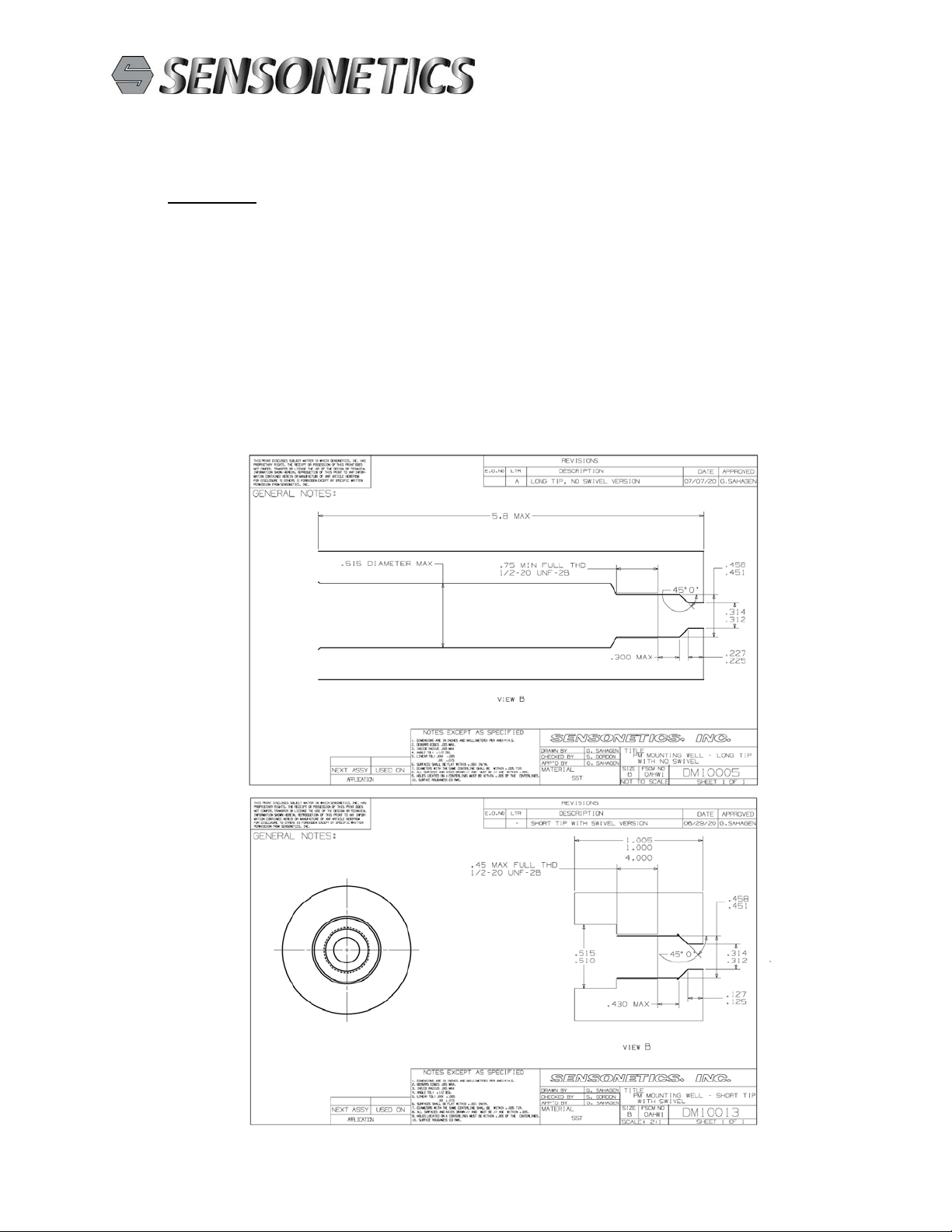
2.2 The transducer mounting-well machining must be checked before installation of the transducer. (Mounting
well must be free of frozen plastic or degraded polymer).
2.3 Transducer should only be removed or installed when the extruder is near operating temperature and there
is no pressure in the barrel. Failure to do so can result in cross-threading and side-force pressure on the
sensor tips, leading to damage and/or improper functioning. No transducer can work properly with a
pinching force on the diaphragm.
3.0 INSTALLATION:
3.1 Prior to installing the transducer into the mounting well, the machining tolerances of the well must be
confirmed. Mounting wells that are out of tolerance are the single most common cause of premature
transducer failure. The use of a mounting well Gage plug (available from Sensonetics) coated with Dykem
Blue will confirm the concentricity, diameter, and the condition of the 45-degree seat. In high abrasion
applications, it is not uncommon to have a burr form at the inner lip of the mounting well which can ruin the
diaphragm.
3.2 The transducer tip should be recessed 0.015" (.3-. 4mm) from the extruder bore. As the extruder barrel
wears, the 0.015" recess will be reduced until the transducer diaphragm is flush with the bore of the
extruder. This is a very precarious position for the transducer. Shims are available from the factory, which
seat on the 45-degree cone and act as a spacer; backing off the transducer diaphragm from the extruder
barrel bore.
3.3 It is not the purpose of the spacer shim to act as a gasket; that is taken care of by the 45º-angle shoulder on
the transducer seat. Spacer shims are seldom required, but they are required when the well depth is less than
design specification due to:
a. Barrel wear.
b. Reaming & Tapping wear.
c. Improper machined depth (even in new machines).
3.4 It is important that the tip of the melt pressure unit be slightly recessed in the barrel, but flush downstream.
This prevents age in the screw area and prevents disruption of laminar flow in the die area.
3.5 The transducer threads should be coated with a high temperature anti-seize compound such as NEVER

11164 Young River Avenue Fountain Valley, CA 92708 Page 2
714-799-1616 phone 714-799-4116 fax Revision B: 06/30/20
SEEZ by Bostik or C5A by Felpro. Liberal use of anti-seize compounds will reduce the chances of galling.
3.6 A Torque wrench should be used to ensure proper mounting torque. In most cases, an adequate seal can be
achieved with less than 40 inch-pounds of force. The maximum mounting torque is 50 inch-pounds.
In no case should 100 inch Pounds be exceeded. If a torque wrench is not available, install the unit two
hands tight in a clean well and, using a 6" adjustable wrench; tighten an additional 1/8 -1/4 turn. Note: The
higher the installation torque, the harder it is for the removal of the transmitter.
3.7 Install the transducer as detailed above in the empty cold machine and calibrate the transmitter per the
following procedure:
4.0 CALIBRATION:
Prior to subjecting the transducer to operating pressure and temperature, it is important to set the end points
to 0.0 Vdc at 0 Pressure and 10.0 Vdc at Full Scale Pressure. There are 2 methods that can be used to
calibrate the transducer:
First method, without a Pressure Calibrator:
4.1.1 With temperature at room ambient (or close to 80 ºF)and with zero pressure applied, adjust reading to 0.0
Vdc by turning “PZERO” zero trim pot under the cover screw located on the electronic case.
4.1.2 Short RCal (Calibrating Resistor) pins together and adjust reading to 8.0 Vdc by turning “PSPAN” spa
trim pot located under the cover screw next to the zero trim pot.
4.1.3 Repeat steps 4.1.1 to 4.1.2 as necessary to fine tune adjustment.
4.2 Second method, with a Pressure Calibrator:
4.2.1 with temperature at room ambient (or close to 80 ºF)and with zero pressure applied, adjust reading to 0.0
Vdc by turning “PZERO” zero trim pot located under the cover screw on the electronic case.
4.2.2 Apply full scale pressure to transmitter and adjust reading to 10.0 Vdc by turning the “PSPAN” span trim
pot located under the cover screw next to the zero trim pot.
4.2.3 Repeat steps 4.2.1 to 4.2.2 as necessary to fine tune adjustment.
4.3 Adjust machine temperature to operating temperature and allow at least 30 minutes for transducer to reach
thermal equilibrium.
4.4 After another 30 minutes soak time, re-adjust zero reading to 0.0 Vdc by turning “PZERO” zero trim pot.
(Make sure there is no pressure applied to transducer at this time).
4.5 Transducer is now ready to use. (NOTE: DO NOT adjust span at any temperature other than 80 ± 10 ºF).
Adjustment of span at another temperature will require calibration with a Pressure Calibrator (see paragraph
4.2).
4.6 Make sure to reset zero occasionally to insure more accurate measurements. Reset span only at room
ambient temperature using RCal method if calibrating without a Pressure Calibrator.
4.7 On SEN-432 models, the temperature sensor of the transducer is factory set to 0.0Vdc at 80 ºF and 10.0
Vdc at 500 or 750ºF unless special calibration is noted on the housing. These settings can be changed if
desired, Consult factory before making any adjustment to “TSPAN”
11164 Young River Avenue Fountain Valley, CA 92708 Page 3
714-799-1616 phone 714-799-4116 fax Revision B: 06/30/20
4.8 All the other models listed above that have thermocouple junctions for temperature measurement are not
adjustable. WARNING: Avoid Cold Starts! DO NOT turn the extruder screw until sufficient soak time has
been allowed. Jog screw several times before running while watching pressure, to avoid cold start damage.
5.0 CLEANING:
5.1 NEVER CLEAN melt pressure transducers using extreme high temperatures such as molten salt baths,
blowtorches, muffle furnaces or any high temperature process, which exceeds 750 ºF. Internal damage to
the sensing elements and conductors will occur.
5.2 PROPER CLEANING procedures for dissolvable polymers are to use the appropriate solvent or di-Me2-
Pyrolidene combined with fine brass wire brushing by hand. For non-dissolving polymers such as PP,
HDPE, PE, PTFE, etc., it is advisable to warm the plastic coated tip to a temperature not to exceed 600 ºF
and gently brass-wire brush the tip and the threads. If large amounts of plastic are present, try cutting and
peeling the plastic from the probe. Do not use this method close to the sapphire diaphragm, since it is
possible to cause damage in this area. Take care not to pry the sapphire diaphragm from the tip using a
"dental" pick.
This manual suits for next models
7
Table of contents
Other SENSONETICS Transducer manuals

Popular Transducer manuals by other brands

Fluke
Fluke PV350 Quick reference guide

MKS
MKS UniMag 971 Operation and installation manual

Minebea
Minebea TMHS-NM Series instruction manual

Airmar
Airmar R299 Owner's guide and installation instructions

Pewatron
Pewatron JX-P420 Series installation guide

Kurt J. Lesker
Kurt J. Lesker 100014434 Operation and maintenance manual


