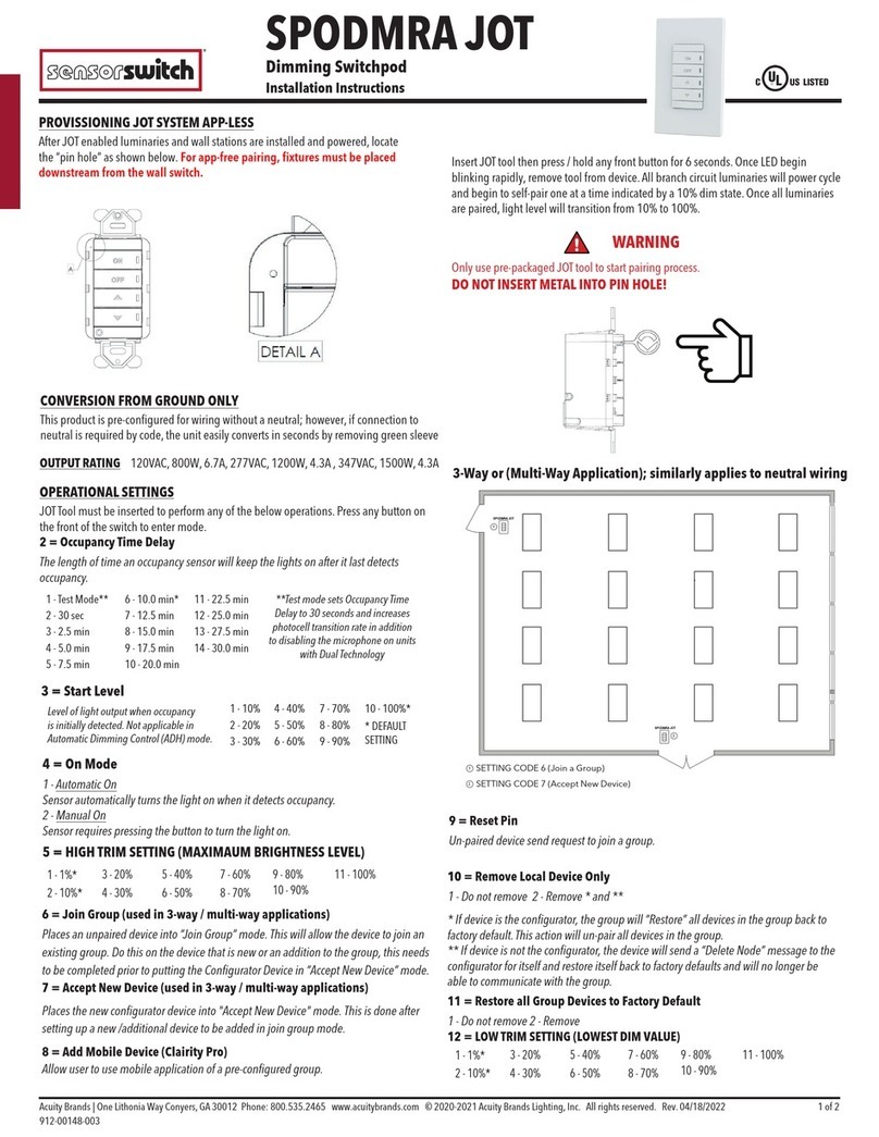
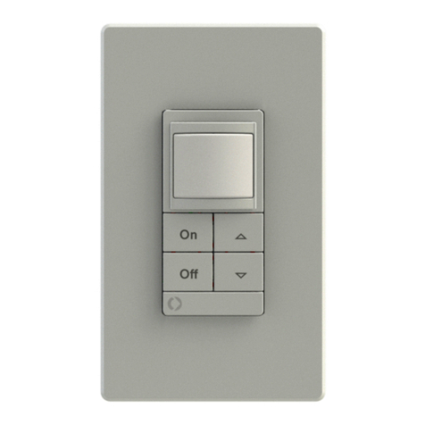
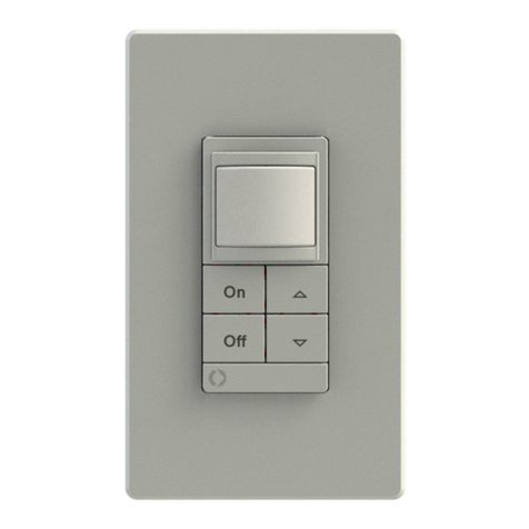
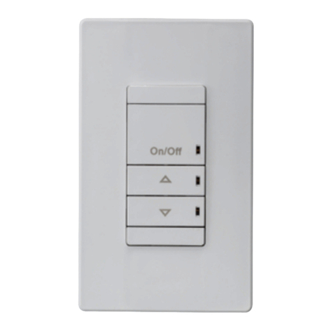
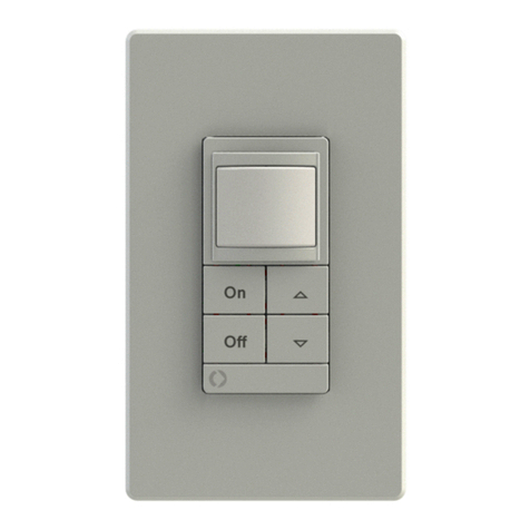
Sensor Switch SPODMR WR Series User manual

Sensor Switch 900 Northrop Road, Wallingford, CT 06492 Phone: 1.800.PASSIVE sensorswitch.com ©2014 Acuity Brands Lighting, Inc. All rights reserved 09/22/14 IS-SPODMR-WR-003 1 of 2
SPECIFICATIONS
WIRELESS FREQUENCY: 902 MHz (RDT™)
WIRELESS RANGE GUIDELINES:
Line of Sight: >100 ft (31 m); e.g. corridor
Plasterboard / Dry Wood: 98 ft (30 m), max 5 walls
Concrete: 32 ft (10 m), max 1 wall/ceiling
MAX PAIRED DEVICES: 20
Wireless Wall Switch Instructions
(Model SPODMR WR xx)
MAXIMUM LOAD:
800 W @ 120 VAC / 1200 W @ 277 VAC
(Fluorescent/Tungsten/LED)
1A @ 24 VAC/VDC
MINIMUM LOAD: None
MOTOR LOAD: 1/4 HP
LOAD FREQUENCY: 50/60 Hz
SILICONE FREE
ROHS COMPLIANT
SIZE: 2.74”H x 1.68”W x 1.63”D
6.96 cm x 4.27 cm x 4.14 cm)
(not including ground strap)
WEIGHT: 5 oz
MOUNTING: Single gang switch box
OPERATING TEMP:
-4º to 122º F (-20º to 50º C)
RELATIVE HUMIDITY
20 to 75% non-condensing
PAIRING
INSTRUCTIONS
1
1
ON
OFF
ON
OFF
A.
1
3x
ON
OFF
B.
1
C.
ON
OFF
2x
LEARN
STATE 23x
ON
OFF
- OR -
PRESS
PRESS
ON
OFF
ON
OFF
REPEAT
STEP C FOR EACH
ADDITIONAL DEVICE
TO PAIR, THEN
PROCEED TO
STEP D.
.
.
G
S
PLEASE NOTE:
a) RELAY TOGGLES WHEN PAIRED WITH A NEW DEVICE.
b) WHILE IN THE LEARN STATE, THE LEDs WILL FLASH
THE PAIRED DEVICE COUNT OR GIVE RANGE WARNING
ERROR CODE.
c) DEVICES EXIT THE LEARN STATE 2 MINS AFTER LAST
DEVICE PAIRED IF LEFT INACTIVE.
1
1
LEARN
STATE
D.
ON
OFF
1x
ON
OFF
WHILE LEDs
FLASH
1
E.
ON
OFF
PAIRING
COMPLETE
ON
OFF
ON
OFF
REPEAT
STEP C FOR EACH
ADDITIONAL DEVICE
TO PAIR, THEN
PROCEED TO
STEP D.
.
.
G
S
PLEASE NOTE:
a) RELAY TOGGLES WHEN PAIRED WITH A NEW DEVICE.
b) WHILE IN THE LEARN STATE, THE LEDs WILL FLASH
THE PAIRED DEVICE COUNT OR GIVE RANGE WARNING
ERROR CODE.
c) DEVICES EXIT THE LEARN STATE 2 MINS AFTER LAST
DEVICE PAIRED IF LEFT INACTIVE.
The following ve procedures should be reviewed completely prior to setting
up wireless switch units for use with CM xx WR wireless sensors or other RDTTM
Wireless devices. Consult the CM xx WR instruction sheet for additional sensor
setup procedures.
Operational Modes
Selection of Auto-On, Manual-On, or Predictive w/ Expiration operating modes.
Step 1. Press and hold both switch buttons for 3 seconds (i.e. until button LEDs
start ashing together)
Step 2. Press switch’s ON button 5 times
Step 3. LED will begin ashing current setting (see selections 1-3 below)
Step 4.To change setting, press switch’s ON button the number of times
corresponding to the new desired setting from the below choices:
1 - Auto-On:
Load will automatically turn on when occupied and o when vacant.
Pressing OFF will turn the load o and disable occupancy detection until ON
is pressed.
2 - Manual-On/Vacancy (*default for -SA option units):
Sensor functions as a vacancy detector, turning load o after occupancy is
no longer detected. Load must be turned on manually by pressing ON
button each time the room is entered. After the sensor times out, there is
a 10 second grace period in which detection of occupancy will automatically
turn the load back on.
3 - Predictive Mode w/ Expiration (*default for non-SA units):
Load will automatically turn on when occupied and o when vacant. Load
can be overridden to o by pressing OFF button.The load will remain o
if the room remains occupied. However, after the room becomes vacant, the
switch will revert back to auto on/o operation after Occupancy Time
Delay expires.
Step 5. Switch’s LED will ash back current setting (repeats 3 times, then exits)
Occupancy Time Delay
The length of time a switch’s relay will remain closed after the last occupied
transmission from a sensor has been received. When paired with CM xx WR
series PIR sensors, the Occupancy Time Delay can be set from the switch (see
below) or from the sensor (recommended). See sensor instruction sheet.
When paired with CM PDT xx WR series Dual Tech sensors, the Occupancy Time
Delay must be set from the sensor (see sensor instruction sheet) and only after
it is paired with the SPODMR WR switch.This ensures that the sensor’s internal
Microphonics time delay matches the switch’s Occupancy Time Delay.
Step 1. Press and hold both switch buttons for 3 sec (until LEDs start ashing)
Step 2. Press switch’s ON button 2 times
Step 3. LED will begin ashing current setting (see selections 1-13 below)
Step 4.To change setting, press switch’s ON button the number of times
corresponding to the new desired setting from the below choices:
1- 30 sec 5 - 10.0 min* 9- 20.0 min 13 - 30.0 min
2 - 2.5 min 6 - 12.5 min 10 - 22.5 min
3- 5.0 min 7 - 15.0 min 11 - 25.0 min
4- 7.5 min 8 - 17.5 min 12 - 27.5 min
Step 5. LED will ash back new setting (repeats 3 times, then exits)
Notes:
1. The sensor Heartbeat Setting will need to be adjusted on the sensor to match
this setting if 5 minutes or under, and be set to 5 minutes for any higher setting.
ADDITIONAL SETTINGS & MODES
Unlearn (Unpair)
When a teach broadcast is received by a switch from a remote device, it is
removed from the unit’s list of learned (paired) devices.
Step 1. Press and hold both switch buttons for 3 seconds (i.e. until button
LEDs start ashing together)
Step 2. Press switch’s ON button 4 times
Notes:
1. While in Unlearn Mode, the unit will rapid ash then slow blink the
number of learned devices, and repeat.
2. Unit stays in Unlearn Mode for 2 minutes, or until one device is
unlearned. Press sensor button 2 times to unlearn (unpair).
3. Each time a new device is unlearned by (e.g. unpaired with) the switch,
the switch will toggle its relay.
Switch Diagnostic / Reset / Unlearn All
Provides options to reset and/or unlearn currently paired remote devices.
Also provides total paired and inactive device count information.
Step 1. Press and hold both switch buttons for 3 seconds (i.e. until button
LEDs start ashing together)
Step 2. Press switch’s ON button 9 times
Step 3. LED will begin ashing current setting (see selections 1-8 below)
Step 4.To change setting, press switch’s ON button the number of times
corresponding to the new desired setting from the below choices:
1 - Do nothing*
2 - Reset settings to factory default and unlearn all
4 - Unlearn all paired devices
5 - Reset settings to factory defaults (without unlearning devices)
6- Learned Device Count
7- Inactive Sensor Count (paired sensors that have stopped transmitting)
8- Unlearn All Inactive Sensors
Step 5. LEDs will ash back current setting (repeats 3 times, then exits)
Switch Status LED Operation
Controls the normal operation of the button’s LEDs on the switch unit.
Step 1. Press and hold both switch buttons for 3 seconds (i.e. until button
LEDs start ashing together)
Step 2. Press switch’s ON button 11 times
Step 3. LED will begin ashing current setting (see selections 1-2 below)
Step 4.To change setting, press switch’s ON button the number of times
corresponding to the new desired setting from the below choices:
1 - LEDs enabled* (indicates current status of relay)
2 - LEDs disabled
Step 5. LED will ash back current setting (repeats 3 times, then exits)
Note: In disabled mode, LEDs will still ash when button is pushed, device
is in Learn or Unlearn mode, or when device is ashing back a setting or
error code.
* Denotes factory setting
Switch Learn Mode (Pairing Mode) - see diagrams A-D above
The operational state when a switch unit will accept teach broadcasts from
remote devices (e.g. sensors). Once received, the remote device will be added to
the switch unit’s list of learned (paired) devices.
Step 1. Press and hold both switch buttons for 3 seconds (i.e. until button LEDs
start ashing together). See Diagram A above.
Step 2. Press switch’s ON button 3 times (Diagram B above). Switch will now
be in“learn mode”
Notes:
1. While in Switch Learn Mode, the switch unit’s LEDs will rapid ash then slow
blink the number of learned devices, and repeat (Diagram C above). See reverse
side for more details regarding device count blinkout.
2. The unit will stay in Switch Learn Mode for 2 minutes after last device was
learned, or until switch’s ON button is pressed (Diagram D above).
3. Each time a new device is learned by (e.g. paired with) the switch, the switch
will toggle its relay.Wait a minumum of 4 seconds before pairing another device.
Sensor Teach Mode - see diagram C above
The operational state of a sensor when it will transmit its sensor ID to facilitate
pairing with other devices.This procedure is valid for CM xx WR series sensors.
For pairing other RDTTM Wireless devices (e.g. rocker switch), consult instructions
for that device.
Step 1.While switch is in Switch Learn Mode, press and release sensor button
2 times (Diagram C above)
Step 2.The sensor’s LED will rapid ash when transmitting
Note:
1. Sensor resumes normal operation after one transmission is sent.
2. Use this procedure to unpair a sensor when a switch is in Unlearn mode.
Pairing a 2nd Switch - see diagram C above
To pair a 2nd SPODMR WR switch or a RDTTM Wireless rocker switch (model
XCR 1PWH) follow below procedure:
Step 1.While the rst SPODMR WR switch is in Switch Learn Mode, press and
release the 2nd switch’s ON button (or rocker button) 3 times
(Diagram C above)
ON
OFF
ON
OFF
ON
OFF
SETUP INSTRUCTIONS
ON
OFF
ON
OFF
ON
OFF
ON
OFF

Sensor Switch 900 Northrop Road, Wallingford, CT 06492 Phone: 1.800.PASSIVE sensorswitch.com ©2014 Acuity Brands Lighting, Inc. All rights reserved 09/22/14 IS-SPODMR-WR-003 2 of 2
COMPLIANCE INFORMATION
SPODMR WR: FCC: VR8-SSIINTR002 CM xx WR: FCC: VR8-SSIINTR003
IC: 7791A-SSIINTR002 IC: 7791A-SSIINTR003
These devices comply with part 15 of the FCC Rules. Operation is subject to the following two conditions: (1) This device may not cause harmful interference, and (2) this device must accept any interference received, including
interference that may cause undesired operation.
CAUTION: Changes or modications not expressly approved by the party responsible for compliance could void the user’s authority to operate the equipment.
CAN RSS-Gen/CNR-Gen:
This device complies with Industry Canada licence-exempt RSS standard(s). Operation is subject to the following two conditions: (1) this device may not cause interference, and (2) this device must accept any interference,
including interference that may cause undesired operation of the device.
Le présent appareil est conforme aux CNR d’Industrie Canada applicables aux appareils radio exempts de licence. L’exploitation est autorisée aux deux conditions suivantes : (1) l’appareil ne doit pas produire de brouillage, et (2)
l’utilisateur de l’appareil doit accepter tout brouillage radioélectrique subi, même si le brouillage est susceptible d’en compromettre le fonctionnement.
Under Industry Canada regulations, this radio transmitter may only operate using an antenna of a type and maximum (or lesser) gain approved for the transmitter by Industry Canada.
To reduce potential radio interference to other users, the antenna type and its gain should be so chosen that the equivalent isotropically radiated power (e.i.r.p.) is not more than that necessary for successful communication.
Conformément à la réglementation d’Industrie Canada, le présent émetteur radio peut fonctionner avec une antenne d’un type et d’un gain maximal (ou inférieur) approuvé pour l’émetteur par Industrie Canada.
Dans le but de réduire les risques de brouillage radioélectrique à l’intention des autres utilisateurs, il faut choisir le type d’antenne et son gain de sorte que la puissance isotrope rayonnée équivalente (p.i.r.e.) ne dépasse pas
l’intensité nécessaire à l’établissement d’une communication satisfaisante.
Note: This equipment has been tested and found to comply with the limits for a Class B digital device, pursuant to part 15 of the FCC Rules.These limits are designed to provide reasonable protection against harmful interference
in a residential installation. This equipment generates, uses and can radiate radio frequency energy and, if not installed and used in accordance with the instructions, may cause harmful interference to radio communications.
However, there is no guarantee that interference will not occur in a particular installation. If this equipment does cause harmful interference to radio or television reception, which can be determined by turning the equipment o
and on, the user is encouraged to try to correct the interference by one or more of the following measures:
—Reorient or relocate the receiving antenna.
—Increase the separation between the equipment and receiver.
—Connect the equipment into an outlet on a circuit dierent from that to which the receiver is connected.
—Consult the dealer or an experienced radio/TV technician for help.
• To reduce the risk of death, personal injury or property damage from re, electric shock, falling parts, cuts/abrasions, and other hazards please read all warnings and
instructions included with and on the xture box and all xture labels.
• Before installing, servicing, or performing routine maintenance upon this equipment, follow these general precautions.
• Installation and service should be performed by a qualied licensed electrician.
• Maintenance should be performed by qualied person(s) familiar with the products’ construction and operation and any hazards involved. Regular maintenance
programs are recommended.
READ AND FOLLOW ALL SAFETY INSTRUCTIONS!
SAVE THESE INSTRUCTIONS AND DELIVER TO OWNER AFTER INSTALLATION
• DO NOT INSTALL DAMAGED PRODUCT! This product has been properly packed so that no parts should have been damaged during transit. Inspect to conrm. Any
part damaged or broken during or after assembly should be replaced.
CAUTION: RISK OF PRODUCT DAMAGE
√ Electrostatic Discharge (ESD): ESD can damage product(s). Personal grounding equipment should be worn
during all installation or servicing of the unit.
√ Do not touch individual electrical components, as this can cause ESD and aect product performance.
√ Do not stretch or use cable sets that are too short or are of insucient length.
√ Do not tamper with contacts.
√ Do not modify the product.
√ Do not change or alter internal wiring or installation circuitry.
√ Do not use product for anything other than its intended use.
WARNING RISK OF BURN OR FIRE
√ Do not exceed maximum wattage, ratings, or published operation
conditions of product.
√ Do not overload.
√ Follow all manufacturer’s warnings, recommendations and
restrictions to ensure proper operation of product.
CAUTION RISK OF INJURY
√ Wear gloves and safety glasses at all times when installing, servicing
or performing maintenance.
WARNING
RISK OF ELECTRIC SHOCK
√ Disconnect or turn o power before
installation or servicing.
√ Verify that supply voltage is correct by
comparing it with the product information.
√ Make all electrical and grounded connections
in accordance with the National Electrical
Code (NEC) and any applicable local code
requirements.
√ All wiring connections should be capped with
UL approved recognized wire connectors.
√ All unused connector openings must be capped.
Scan QR code to access
video demonstrations
http://bit.ly/1aszSqd
ON
OFF
LOAD
Model #: SPODMR WR
H
GND
Model #: CM xx WR
EXAMPLE APPLICATION DIAGRAMS
WIRING & INSTALLATION
GND
H
N
LIGHTING
LOAD
BLK
BLK
N
BLACK* - Line/Input
BLACK* - Load/Output
Silver Screw - Neutral
Green Screw - Ground
*BLACK wires
can be
reversed
}
WIRE COLOR KEY
1. Turn o power to switch box at the circuit breaker.
2. Connect Ground wire to the GREEN screw.
3. Connect Neutral wire to the SILVER screw.
4. Connect one BLACK wire to Line power. Use a wire nut to
secure connection.
5. Connect second BLACK wire to Load. Use wire nut to secure
connection.
6. Ax switch and cover to wall using provided screws.
7. Turn power back on to switch box.
SINGLE-LEVEL CONTROL:
For Bi-level applications, put both SPODMR WR switches into Learn mode and then pair
all sensors. Do not pair the SPODMR WR devices to each other. Note one switch should
be set to Manual On/Vacancy operating mode.
BI-LEVEL CONFIGURATION:
ON
OFF
LOAD
H
GND
BLK
BLK
Model #
XCR 1PWH Model #: SPODMR WR
H
ON
OFF
GND
BLK
BLK
Model #: SPODMR WR
Model #:
CM xx WR
For 3-way applications using two SPODMR WR switches, each switch must be individually paired with
the other switch and all sensors. For example, put the rst SPODMR WR in Learn mode and pair the other
SPODMR WR switch and all sensors.When complete, put the second SPODMR WR switch in Learn mode and
pair the rst SPODMR WR and all sensors. Pairing any one SPODMR WR switch with a wireless rocker switch
(model #XCR 1PWH) will also provide 3-way functionality.
MULTIWAY (3-WAY) CONFIGURATION:
N
N
LOAD 1
H
ON
OFF
ON
OFF
N
GND GND
LOAD 2
BLK
BLK
BLK
BLK
H
Model #: SPODMR WR
Model #: CM xx WR
Model #: SPODMR WR (SA)
WARRANTY
5-year limited warranty. Complete warranty terms located at
www.acuitybrands.com/CustomerResources/Terms_and_conditions.aspx
AS in U.S.A.SEMBLED
TITLE 24 SYSTEM COMPONENT
C US LISTED
WHILE IN LEARN OR UNLEARN MODE:
PAIRING/DEVICE COUNT: During pairing, LEDs rapid ash together, pause, then slow ash 1x for each learned
(paired) device, wait 2 seconds, and then repeat (e.g., for 4 paired devices the LEDs would rapid ash, pause,
slow ash 4x, pause, then repeat).
RANGE WARNING: A double rapid ash indicates a paired device may be at the limit of the wireless range.
LED STATUS INDICATORS & ERROR CODES
WHILE IDLE:
SENSOR LOW BATTERYWARNING: A rapid ash followed by 3 blinks indicates a paired sensor has low battery.
LOST TRANSMISSION ERROR CODES: If all paired occupancy sensors stop transmitting, 15 minutes after the last
transmission from the last occupancy sensor the LEDs will begin blinking an error code (rapid ash followed
by a single blink) and the switch will enter toggle mode, defaulted On. Clear error code by pairing a new
occupancy sensor, issuing an Unlearn All command or initiating an Unlearn All Inactive Devices command.
Other Sensor Switch Switch manuals
Popular Switch manuals by other brands
Electro Cam
Electro Cam Plus PS-6144 Series Programming & installation manual
Zektor
Zektor HDMI5 user manual

JustCom
JustCom JC-M104U user manual

Moxa Technologies
Moxa Technologies PT-G7509 Hardware installation guide
Transition Networks
Transition Networks LAN MASTER 33022.B user manual
Cisco
Cisco CBS Series Get to know
3Com
3Com 3C16611 - SuperStack II Dual Speed Hub 500 user guide
Stromag
Stromag 51 Series Translation of the original assembly instruction
Link electronics
Link electronics 860-XL1616H Routing Switchers 860-XL1616H Specification sheet
VOLKTEK
VOLKTEK NSH-9309 user manual

Ross
Ross Carbonite Black Series Operation manual
Phoenix Contact
Phoenix Contact FL SWITCH SMCS 16TX Installation notes
