Sensortech Systems ST-3300 Series User manual
© Sensortech Systems, Inc. 2016 Page 1 of 13 Rev.8-2016
ST-3300
Ceramic Face Sensor
with Attached Sensor Electronics Unit
Installation Instructions
Sensortech Systems, Inc.
2221 E. Celsius Avenue Unit B
Oxnard, California USA 3030
805- 81-3735 main
805- 81-3738 fax
www.sensortech.com

© Sensortech Systems, Inc. 2016 Page 2 of 13 Rev.8-2016
ST-3300 Low Temperature Moisture Measurement System
The main components in the system are:
3.
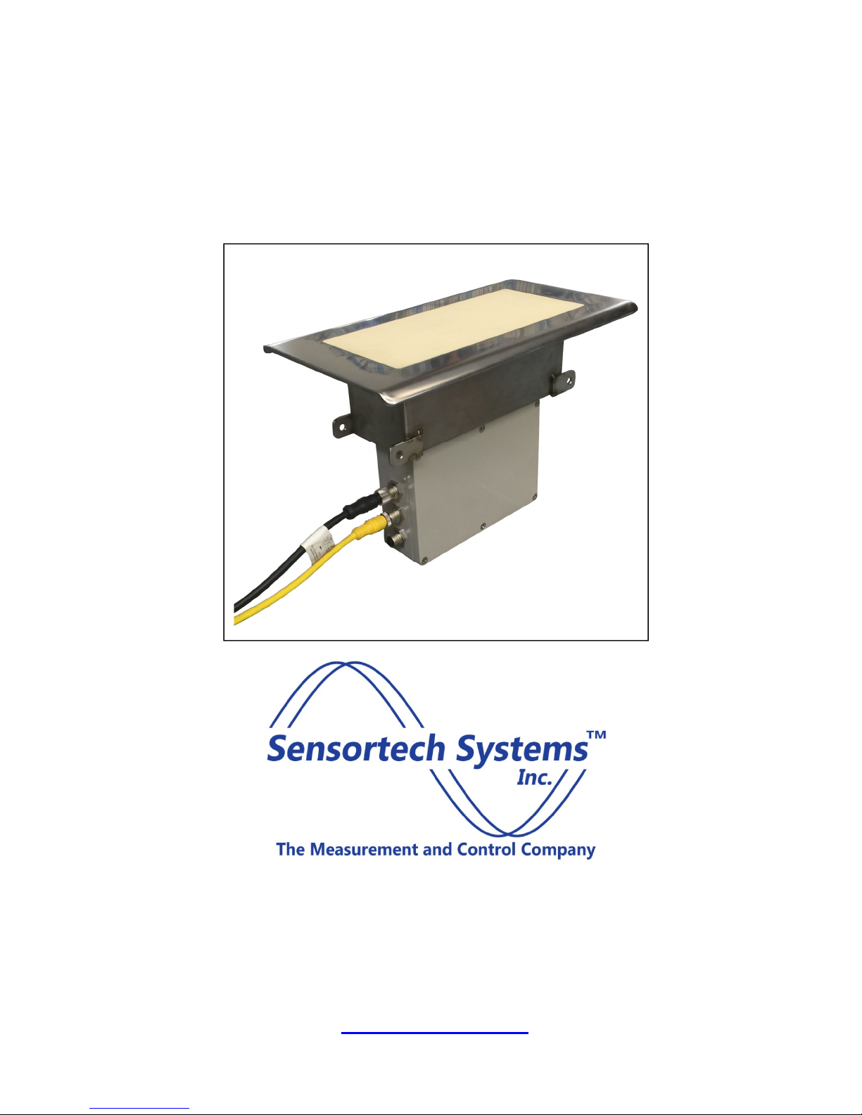
Fi ure
1
.
Ceramic Face Sensor Antenna with
Attached Sensor Electronics Unit
Power/Interface Option
2. ST-3300 I/O Unit – a NEMA4 rated metal enclosure
containing +/-15V DC power supply and control
signals for the Ceramic Face Sensor with Attached
Sensor Electronics Unit. The I/O Unit connects to
the user’s A/C power and provides terminal blocks
for user interface to RS-485, 4-20mA output and
Digital Input signals.
1. ST-3300 Ceramic Face Sensor with Attached
Sensor Electronics Unit – a ceramic face sensor
designed to be in contact with the board product
mounted between rollers. T
he Sensor Electronics
Unit is mounted directly below the Sensor
Antenna. The Sensor is rated for +32 to +122°F
(0 to +50°C) operation. The Sensor Electronics
Unit is contained in a NEMA4 rated metal
enclosure containing the RF moisture
measurement and control electronics. Power
requirements are +15V/-15V dual 40W supply.
Communications are via RS485 and self-
powered, isolated 4-20mA output. The
Power/Interface Option shown below which
conveniently provides necessary power and I/O
connectivity.
Fi ure
2
.
I/O Unit

© Sensortech Systems, Inc. 2016 Page 3 of 13 Rev.8-2016
Fi ure
3
.
System Wirin Dia ram

© Sensortech Systems, Inc. 2016 Page 4 of 13 Rev.8-2016
Fi ure
4
.
Sensor Installation Dia ram

© Sensortech Systems, Inc. 2016 Page 5 of 13 Rev.8-2016
Fi ure
5
.
12 x 7 inch (30.48 x 17.78cm) Ceramic Face Sensor Dimensions

© Sensortech Systems, Inc. 2016 Page 6 of 13 Rev.8-2016
Fi ure
6
.
Example of Mountin Saddle for Ceramic Face Sensor Installation

© Sensortech Systems, Inc. 2016 Page of 13 Rev.8-2016
ST-3300 Ceramic Face Sensor Installation Guidelines
Locatin the Sensor
Select a location to install the Sensor where the board product being measured will remain flat
during travel over the Sensor location for the full length or width of board.
Avoid locations where the contact (vertical height) between the board and Sensor may change
during board travel due to changing slope or roller height change on conveyor.
Care must be taken to position the Ceramic Face Sensor level with the top of the adjacent rollers.
Maintaining contact with the ceramic face and preventing vertical board movement while arriving,
travelling over and leaving the Sensor results in the best measurement accuracy.
A typical Sensor mounting location is using the recommended saddle or a Mounting Beam
supported by height adjustable posts mounted to the cement floor centered between level rollers
approx.6 to 8 inches (15-20cm) apart.
Preparin for the installation
1. Select a suitable location for the Ceramic Face Sensor where the spacing between rollers
allows the installation of the Sensor so that the board travels smoothly and evenly
approaching and leaving the Sensor location. This requires level rollers. Do not mount any
portion of the ceramic face of the Sensor below belts or metal framework. The Sensor length
should be aligned so that the entire ceramic face is covered by the board stream. Normal
measurement area is x 5 inches (22. x 12.7cm) for the Sensor with an overall size of 12 x
7 inches (30.5 x 17.8cm). Allow for some side to side board movement.
2. Fabricate support posts and mounting for installing the Sensor on posts attached to the
cement floor to reduce vibration. High vibration may damage the Sensor. Ensure the support
posts have height adjustment for Sensor to roller and board alignment.
3. Two M12 cables connect the smart sensor to the I/O unit. We recommend these cable be
run through conduit for their protection.
4. Run cables for Low Voltage Signals from the I/O Unit to the plant control panel in conduit or
cable tray.
5. The I/O Unit requires single phase 50-60 Hz 0-250VAC @ 0.1KW.
6. Connect cabling to I/O Unit terminal blocks for A/C Power, RS-485 serial links and/or a 4-
20mA output for moisture value. See Table 1 & 2.
7. Run 14-18AWG Earth Ground wire from local ground point to Sensor Antenna mounting
location and to I/O Unit mounting location. This ground is for RF shielding and is required for
best measurement accuracy.
Important: Do not mount the Sensor where excessive heat transfer will occur. Operating
temperature in excess of 140°F 60°C will result in permanent damage.
Provide a local Earth Ground for the Sensor. Ensure a mounting tab of the Sensor is
connected to local Earth Ground. Add a 14-18 AWG direct wire connection from the
Sensor Antenna to a local Earth Ground potential. Ensure the Sensor Antenna is also
grounded to a process frame or conveyor frame, etc. This is not a safety requirement, but
may influence instrument performance.

© Sensortech Systems, Inc. 2016 Page 8 of 13 Rev.8-2016
Mountin the Sensor
The Sensor is typically mounted after the dryer between rollers level with the top of adjacent
roller surfaces. The Ceramic Face Sensor with Attached Sensor Electronics Unit is rated from
0°C to 50°C ambient temperature and should be mounted on a low vibration adjustable posts
mounted to the cement floor. The Sensor is attached to the mounting saddle or mounting beam
using the four mounting holes on the ends of the Ceramic Face Sensor frame (see Figure 5 & 6).
The Ceramic Face Sensor construction allows board product to contact the ceramic face for
moisture measurement.
The Ceramic Face Sensor is attached to the Mounting Saddle or mounting beam using adjustable
vertical posts with the four 0.25 in (6.3mm) diameter holes on the tabs located on each end of the
Sensor.
An important alignment is for the Ceramic Face Sensor to be level with the product being
measured. If one end of the ceramic face is further away (not in contact) with the product than the
opposite end, it will be less sensitive to changes in moisture than the end of the ceramic face that
is in contact (closer) to the product.
Board product should be in contact with the Ceramic Face Sensor with no air gap between the top
of the Sensor to the bottom of the board product for the full length and wide of the ceramic face.
The antenna and sensor should be isolated as much as possible from conveyor vibration.
Vibration can loosen nuts, bolts, and electronic components.
Due to the close roller spacing for non-rigid board products, it may be necessary to shorten a roller
located where the Sensor will be installed. See Figure 4.
Levelin the Rollers
Use a level or straight edge that spans at least 6 rollers. Lay the level or straight edge across the
three rollers before the Sensor and three rollers after the Sensor. Place level on the rollers near
the bearing ends.
Shim the two outer rollers’ bearing assemblies so that they are level.
Shim the remaining four rollers’ bearing assemblies so that each roller is within 0.01 inches
(.25mm) of level.
Lay the level along the first roller. Shim its bearing assembly on the other side so that it is level
lengthwise.
Lay a level across the six rollers near their ends.
Shim the last roller’s bearing assembly so that it is level with the first roller.
Shim the remaining four rollers’ bearing assemblies so that each roller is within 0.01 inches
(.25mm) of level.

© Sensortech Systems, Inc. 2016 Page 9 of 13 Rev.8-2016
Bearing
Shim
Conveyor
Frame
Level
Rollers
Level
Roller
Fi ure
7
.
Example of Roller Ali nment
© Sensortech Systems, Inc. 2016 Page 10 of 13 Rev.8-2016
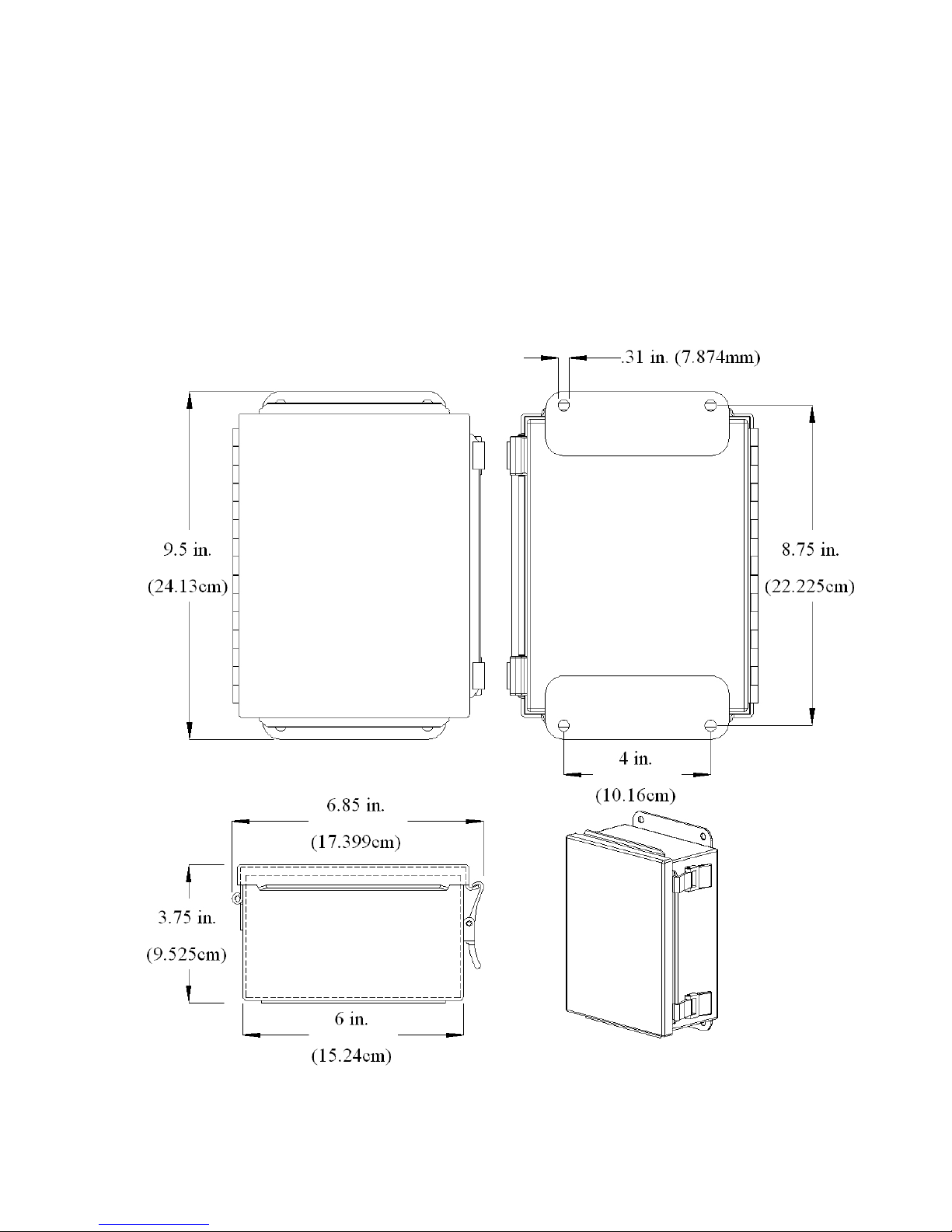
Mountin the I/O Unit
The ST-3300 I/O Unit is typically mounted near the Sensor in a conveniently accessible location
for periodic maintenance and calibration tasks. Two standard M12 cables are used to connect
the Sensor Electronics Unit to the I/O Unit. The M12 cables come in standard lengths of 33 ft.
(10m). An important consideration for the I/O Unit location is the need to maintain the ambient
temperature below 50°C.
The I/O Unit is wired via two wire 4-20mA and/or 5 wire RS-485 interface to the plant master
control for monitoring and control.
Fi ure 8.
I/O Unit Dimensions

© Sensortech Systems, Inc. 2016 Page 11 of 13 Rev.8-2016
Fi ure
9
.
I/O Unit Terminal Board Layout

© Sensortech Systems, Inc. 2016 Page 12 of 13 Rev.8-2016
I/O Unit Connector / Terminal Block Si nals
Table 2: EXTERNAL SIGNALS
Internal Si nal Connector Pin External Si nal External Si nal Description
+15VDC J5 1 Digital Input +15VDC
I/O Unit Internal +15VDC (< 100mA) to power
Proximity Detector or Micro-Switch
Ground J5 2 Digital Input Ground
I/O Unit Internal Ground to power Proximity
Detector or Micro-Switch
Dig In + J5 3 Digital Output+
Proximity Detector or Micro-Switch Output for
gated measurement control
Dig In - J5 4 Digital Output-
Proximity Detector or Micro-Switch Output for
gated measurement control
4-20mA Out + J6 1
User PLC/Controller
Positive 4-20mA Input
Moisture or Product Temperature measurement
output value
4-20mA Out - J6 2
User PLC/Controller
Negative 4-20mA Input
Moisture or Product Temperature measurement
output value
G J7 1
Users RS-485 Bus B
Ground User PLC/Controller RS-485 Ground
OP- J7 2
Users RS-485 Bus B
RxD- Users PLC/Controller RS-485 RxD-
OP+ J7 3
Users RS-485 Bus B
RxD+ Users PLC/Controller RS-485 RxD+
IP+ J7 4
Users RS-485 Bus B
TxD+ Users PLC/Controller RS-485 TxD+
IP- J7 5
Users RS-485 Bus B
TxD- Users PLC/Controller RS-485 TxD-
G J8 1
Users RS-485 Bus A
Ground Users PLC/Controller RS-485 Ground
OP- J8 2
Users RS-485 Bus A
RxD- Users PLC/Controller RS-485 RxD-
OP+ J8 3
Users RS-485 Bus A
RxD+ Users PLC/Controller RS-485 RxD
IP+ J8 4
Users RS-485 Bus A
TxD+ Users PLC/Controller RS-485 TxD+
IP- J8 5
Users RS-485 Bus A
TxD- Users PLC/Controller RS-485 TxD-
G J 1 Safety Ground Safety Ground ( 0-250VAC 50-60Hz)
L J 2 Line / Hot Line / Hot ( 0-250VAC 50-60Hz)
N J 3 Neutral Neutral ( 0-250VAC 50-60Hz)
Table 1: INTERNAL SIGNALS
From
To
Si nal Color Connector Pin Connector Pin
IP+ (RS-485) BRN J3 1 J4 or to Users external TxD+ 4
IP- (RS-485) WHT J3 2 J4 or to Users external TxD- 5
OP- (RS-485) BLU J3 3 J4 or to Users external RxD- 2
OP+ (RS-485) BLK J3 4 J4 or to Users external RxD+ 3
Ground (RS-485) GRN/YEL J3 5 J4 or to Users external Ground 1
Ground (RS-485) GRN/YEL J4 1 J3 5
OP- (RS-485) BLU J4 2 J3 3
OP+ (RS-485) BLK J4 3 J3 4
IP+ (RS-485) BRN J4 4 J3 1
IP- (RS-485) WHT J4 5 J3 2

© Sensortech Systems, Inc. 2016 Page 13 of 13 Rev.8-2016
ST-3300 System Power-up
Please verify the following before applying power to the ST-3300 I/O Unit:
1. Verify Earth Ground connection to Sensor Antenna side mounting tab.
2. Securely tighten the M12 low voltage cables on top of Sensor Electronics Unit.
3. If used, verify connection on Sensor Electronics Unit to Product Temperature monitor.
4. Securely tighten the M12 low voltage cables on side of I/O Unit.
5. Verify connections on I/O Unit Terminal Block Connector J8 to Users PLC/Controller RS-485 signals.
6. Verify connections on I/O Unit Terminal Block Connector J6 to Users PLC/Controller 4-20mA signals.
7. If used, verify connections on I/O Unit Terminal Block Connector J5 to Users Digital Input signals.
8. Verify connections on I/O Unit Terminal Block Connector J to single phase 0-250V A/C with Earth
Ground.
Quick ST-3300 Calibration
Allow the ST-3300 System to warm-up >60 minutes to fully stabilize before calibration and use
for process measurement.
Pre-Zero:
Wipe the ceramic face of the sensor clean with a broom or dry cloth. Ensure the ceramic face is
clean and dry before performing a Pre-Zero calibration. Open the lid of the IO Unit and press the
button labelled ZERO (see Figure ). The green STATUS LED with turn on for 2 seconds and
turn off after the calibration is complete. If there is an error during calibration, the STATUS LED
(D1) will blink on and off 10 times. When the Sensor is calibrated the moisture display value on
the sensor should be 0.
Standardization:
Wipe the ceramic face of the sensor and Standardization Plate clean with a broom or dry cloth.
Ensure the ceramic face of the Sensor and the and Standardization Plate are clean and dry
before performing a Standardization calibration.
Place the 12 x 7 inch (30.5 x 17.8cm) Standardization Plate, provided with the Sensor, directly on
top of the Ceramic Face Sensor. Ensure the plate is level and flat on the Sensor measurement
area. Open the lid of the IO Unit and press the button labelled STANDARDIZE (see Figure ).
The green STATUS LED (D1) will turn on for 2 seconds and turn off after the calibration is
complete If there is an error during calibration, the STATUS LED will blink on and off 10 times.
Note the reference value = 5 for the Ceramic Face Sensor Standardization Plate. When the
Sensor is calibrated the moisture display value with the Standardization Plate on top of the
sensor should be 5.
See the ST-3300 Technical Manual for more information.
For additional technical support, email us at [email protected]m or call 805- 81-3735
Monday thru Friday between 8AM-4:30PM Pacific Standard Time.
Other manuals for ST-3300 Series
1
Table of contents
Other Sensortech Systems Accessories manuals


