Sensortech Systems ST-3300 Series User manual

ST-3300 Smart RF Sensor
Technical Manual
2221 E. Celsius Avenue, Unit B
Oxnard, California USA 93030
Tel ( 05) 9 1-3735
Fax ( 05) 9 1-373
www.Sensortech.com

ST-3300 Smart RF Sensor Technical Manual
Screen 2 of 60
© Sensortech Systems, Inc. 2016
Sensortech Systems, Inc. is disclosing this material to you solely for use to operate hardware devices and
software we manufacture. You may not reproduce, distri ute, repu lish, download, display, post, or transmit
the documentation in any form or y any means including, ut not limited to, electronic, mechanical,
photocopying, recording, or otherwise, without the prior written consent of Sensortech Systems. Sensortech
Systems expressly disclaims any lia ility arising out of your use of the documentation. Sensortech Systems
reserves the right, at its sole discretion, to change the documentation without notice at any time. Sensortech
Systems assumes no o ligation to correct any errors contained in the documentation, or to advise you of any
corrections or updates. Sensortech Systems expressly disclaims any lia ility in connection with technical support
or assistance that may e provided to you in connection with the information.
THE DOCUMENTATION IS DISCLOSED TO YOU “AS-IS” WITH NO WARRANTY OF ANY KIND. SENSORTECH
SYSTEMS MAKES NO OTHER WARRANTIES, WHETHER EXPRESS, IMPLIED, OR STATUTORY, REGARDING THE
DOCUMENTATION, INCLUDING ANY WARRANTIES OF MERCHANTABILITY, FITNESS FOR A PARTICULAR PURPOSE,
OR NONINFRINGEMENT OF THIRD PARTY RIGHTS. IN NO OCCURRENCE WILL SENSORTECH SYSTEMS BE LIABLE
FOR ANY CONSEQUENTIAL, INDIRECT, EXEMPLARY, SPECIAL, OR INCIDENTAL DAMAGES, INCLUDING ANY LOSS
OF DATA OR LOST PROFITS, ARISING FROM YOUR USE OF THE DOCUMENTATION.
© 2016 Sensortech Systems, Inc. All rights reserved.
Sensortech, the Sensortech.com logo, and other designated rands included herein are trademarks of
Sensortech Systems, Inc. All other trademarks are the property of their respective owners.

ST-3300 Smart RF Sensor Technical Manual
Screen 3 of 60
© Sensortech Systems, Inc. 2016
Preface
About The Manual
This manual is intended to provide a technical reference for configuring and operating the newest Sensortech
ST-3300 Series Smart RF Sensors and software. Installation guidelines are provided in the Wiring and Installation
document provided with the Sensor. New and experienced users will enefit from the detailed technical
information and operating instructions for Sensortech hardware and software options and accessories.
In this manual, the ST-3300 Series Smart RF Sensors are also referred to y the general term “Gauge”.
Hardware Revisions and Software Versions covered y this manual:
ST-3300 Series Hardware Revision: A (and a ove)
ST-3300 Series Firmware Version: 0.04 (and a ove)
ST-3300 Series Configuration Software Version: 1.000 (and a ove)
The manual is organized as follows:
1. Quick Start Guide
2. Sensor and hardware installation information.
3. Sensortech software installation and PC requirements.
4. Overview of the Sensor and software configuration.
5. Overview of Product Cali ration using the Sensor.
6. APPENDIX.
7. RS-485 ModBus Specifications

ST-3300 Smart RF Sensor Technical Manual
Screen 4 of 60
© Sensortech Systems, Inc. 2016
Table of Contents
Preface ........................................................................................................................................................................3
A out The Manual ..............................................................................................................................................3
Ta le of Contents .......................................................................................................................................................4
Introduction ................................................................................................................................................................6
Sensor Physical Installation ........................................................................................................................................6
System Overview ........................................................................................................................................................6
Sensor Electronics ......................................................................................................................................................8
Resonant Frequency Dielectric Measurement ................................................................................................ 11
Open Frame Planar Sensor Antenna Measurement ....................................................................................... 16
Sensor Antenna Design ........................................................................................................................................... 19
Theory of Operation ................................................................................................................................................ 20
Radio Frequency Dielectric Measurement ...................................................................................................... 20
Moisture Determination y Dielectric Measurement ..................................................................................... 21
ST-3300 Configuration Software ............................................................................................................................. 22
Minimum Host PC Requirements .................................................................................................................... 22
Software installation ....................................................................................................................................... 22
Connecting to the Sensor using the RS-485 Interface ............................................................................................. 23
RS-485 Serial Communication - Host PC/PLC/Controller to I/O Unit .............................................................. 23
ST-3300 Configuration Program Operation ............................................................................................................. 24
Main Screen – at Startup ................................................................................................................................. 24
Main Screen – Sensor Connected .................................................................................................................... 25
Setup Screen .................................................................................................................................................... 27
Diagnostics Screen ........................................................................................................................................... 28
Measure Configuration Screen ........................................................................................................................ 30
Product Configuration Screen ......................................................................................................................... 34
I/O Configuration Screen ................................................................................................................................. 35
Cali ration Screen ........................................................................................................................................... 36
Offset Mode ..................................................................................................................................................... 37
Offset Cali ration Procedure ........................................................................................................................... 38
Linear Mode ..................................................................................................................................................... 38

ST-3300 Smart RF Sensor Technical Manual
Screen 5 of 60
© Sensortech Systems, Inc. 2016
Suggestions for taking product samples.......................................................................................................... 40
Maintenance Screen ................................................................................................................................................ 41
Pre-Zero Cali ration ................................................................................................................................................ 42
Standardize Cali ration ........................................................................................................................................... 43
Pre-Zero Cali ration Procedure - using the Configuration Program ....................................................................... 44
Standardize Cali ration Procedure - using the Configuration Program .................................................................. 44
Pre-Zero Cali ration Procedure - using the I/O Unit Push- uttons ........................................................................ 45
Standardize Cali ration Procedure - using the I/O Unit Push- uttons ................................................................... 45
Appendix .................................................................................................................................................................. 46
Sensor Electronics Unit External Connectors .................................................................................................. 46
I/O Unit External Connectors .......................................................................................................................... 47
I/O Unit Terminal Board Layout ...................................................................................................................... 48
I/O Unit Terminal Board Signals ...................................................................................................................... 49
Sensor Status and Error Messages .................................................................................................................. 50
ST-3300 Sensor RS-485 Communications Interface Specification ........................................................................... 51
ST-3300 MODBUS-RTU Serial Communications Interface............................................................................... 51

ST-3300 Smart RF Sensor Technical Manual
Screen 6 of 60
© Sensortech Systems, Inc. 2016
Introduction
Thank you for choosing Sensortech for your moisture measurement and analysis needs. The Sensortech ST-3300
Series of Smart RF Sensors are designed for use in industrial environments and provide the most sophisticated
on-line Sensors availa le, offering unmatched accuracy and relia ility.
The Sensors are shipped with all the accessories and custom options ordered. Please compare the contents with
the packing list to ensure all items are accounted for. If any items are missing or damaged, please contact
Sensortech immediately for further assistance.
Sensor Physical Installation
Every Sensor installation is unique and specific installation instructions are provided for the most common and
custom Sensor Application Interfaces. Please refer to the ST-3300 Wiring and Installation Guide for your specific
application.
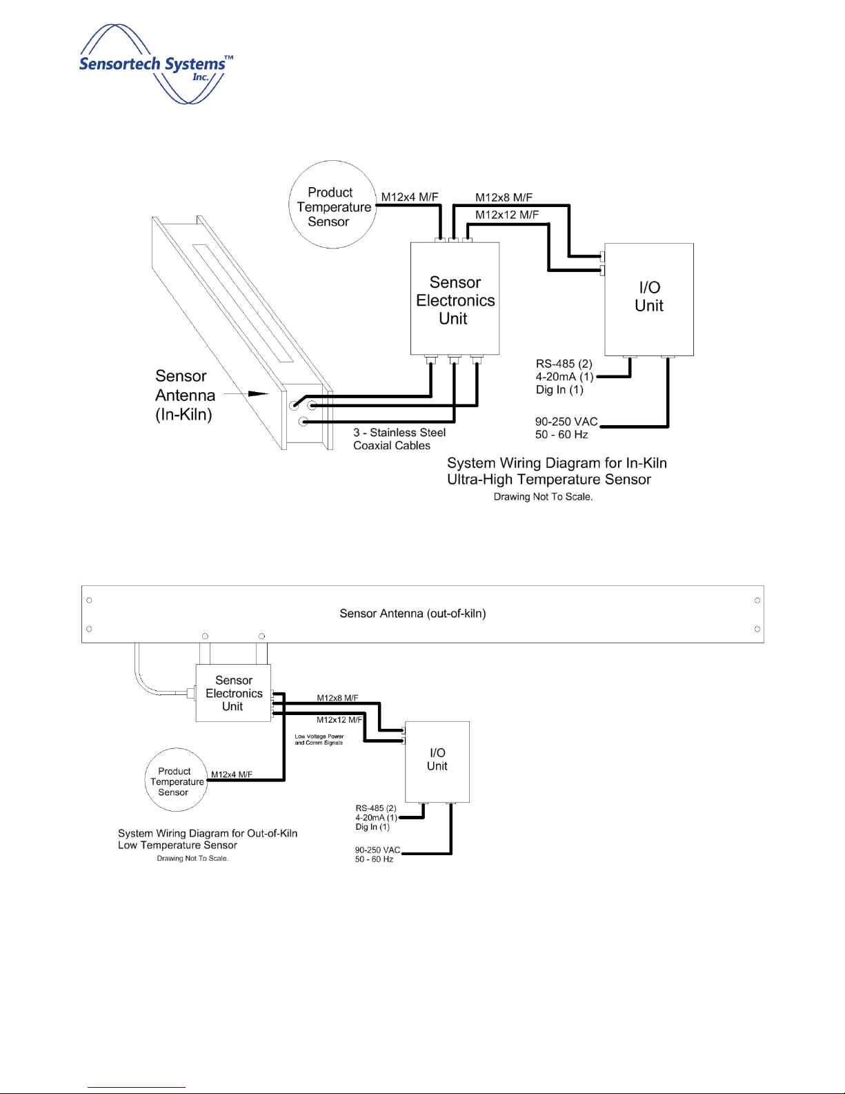
System Overview
The ST-3300 Series Sensor is a complete measurement and interface system where all signal processing and
control functions are self-contained. It features multiple interface protocols including one isolated 4-20mA
output, an RS-485 serial communication port, a Digital Input and a Product Temperature Input. Optional
communications protocols include OI-6000 Operator Interface, Ethernet TCP/IP, DeviceNet, PROFIBUS,
PROFINET and EtherNet/IP as well as digital inputs and outputs for external sample gating and control.
The ST-3300 System is composed of the following components:
Sensor Antenna - an antenna that is located in close proximity to the Product eing measured and is either
directly attached for low temperature applications or remotely located for high temperature applications. The
Sensor Antenna is connected to the Sensor Electronics Unit through coaxial ca les.
Sensor Electronics Unit - a NEMA rated metal enclosure which houses 2 PCB’s – the RF PCB and the Processor
PCB. The RF PCB generates signals sent to the Sensor Antenna and provides frequency and voltage signals to the
Processor PCB for moisture and temperature value calculations. It connects to the I/O Unit and the Sensor
Antenna via M12 for power and signals as well as coaxial ca les to measure product moisture. The Processor
PCB controls the RF PCB and to read and manage data on the analog and digital interfaces.
I/O Unit - a NEMA rated metal enclosure which provides +/-15VDC power to the Sensor and allows the user to
install wires onto the terminal locks and connectors mounted on the I/O Unit PCB to provide AC power and
external analog and digital interfaces.
Product Temperature Transducer - a user defined peripheral pyrometer or transducer module that connects to
the Sensor Electronics Unit via a M4 x 4 pin connector for 4-20mA or voltage input via an M12 x 4 ca le.
ST-3300 Smart RF Sensor Technical Manual
Screen 7 of 60
© Sensortech Systems, Inc. 2016
Figure 1: Example of In-Kiln Open Frame Planar Sensor System
Figure 2: Example of Out-of-Kiln Open Frame Planar Sensor System

ST-3300 Smart RF Sensor Technical Manual
Screen of 60
© Sensortech Systems, Inc. 2016
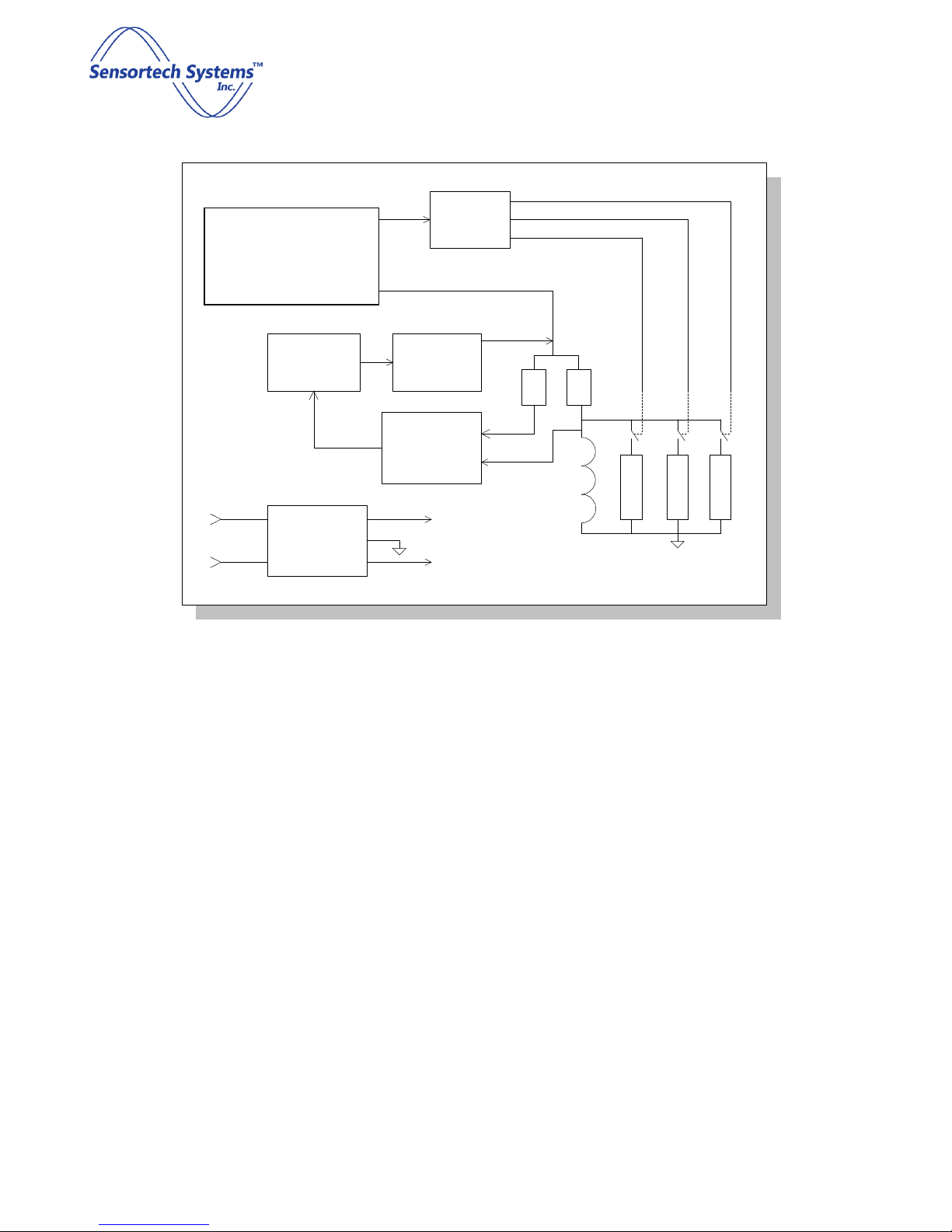
Sensor Electronics
The heart of the ST-3300 is a sophisticated dielectric Sensor. The Sensor utilizes state of the art phase lock loop
technology. High speed logic and ultra-high andwidth operational amplifiers enhance performance. A
microprocessor controls the RF measurement circuit and communicates with user defined protocol interfaces.
Figure 3 shows a lock diagram of the Sensor electronics.
Measurement is made y switching etween one of three RF channels: CA, CH, CL and Sensortech Systems
developed and patented a specific method of dielectric determination using radio frequency. This is known as
the resonant frequency technique. The purpose of the reference channels is to sta ilize the Sensor over a wide
range of am ient conditions. The three frequencies are measured y an on oard microprocessor and form the
inputs to a proprietary algorithm used to eliminate most drift factors.
CA connects to the Sensor Antenna element which is in close proximity to the product eing measured. CH
connects to the High Reference element and CL connects to the Low Reference element for precision reference
calculations.
Only one channel is switched in circuit per measurement sample, this forms a parallel tuned circuit with the
inductor. The resonant frequency of this network constitutes the "lock frequency" of the phase lock loop.
ST-3300 Smart RF Sensor Technical Manual
Screen 9 of 60
© Sensortech Systems, Inc. 2016
The lock diagram of Figure 3 shows the inductor L forming a parallel tuned circuit with one of three channel
capacitances, C
X
. One capacitor is the Sensor electrode next to the product and the other two are reference
frequencies. Switching is performed y PIN diodes. The micro-processor sends control signals to measure each
channel sequentially.
The resulting frequency measurements are:
F
S
= Sensor Antenna Frequency
F
H
= High Reference Frequency
F
L
= Low Reference Frequency
The raw moisture value for Moisture is calculated from the equation:
Moisture = STD * B coefficient * (D
R
– Pre-Zero) + C coefficient
where: B coefficient = slope
cali ration coefficient for Product selected (SPAN)
C coefficient = offset cali ration coefficient for Product selected (ZERO)
STD = Standardization Factor (calculated)
D
R
= calculated raw dielectric value
Pre-Zero = calculated raw dielectric value with empty Sensor – air only from Pre-Zero Cali ration
Opto/
Isolator
Driver/
Isolator
Voltage
Controlled
Oscillator
Automatic
Gain
Control
A/R Sw
Pin
Diode
Drivers
Phase
Detector
R R
C
H
C
L
C
A
Freq.
out
Isolated
Power
Supply
+5v
-5v
-12v
+12v
Figure 3: Sensor RF PCB Block Diagram
Micro-processor and
Control Logic

ST-3300 Smart RF Sensor Technical Manual
Screen 10 of 60
© Sensortech Systems, Inc. 2016
The Sensor measurement results are sent from the Sensor Electronics Unit to the I/O Unit via RS-485 interface.
The I/O Unit provides +/-15V power supply for the Sensor Electronics Unit and terminal oard connectors for
connection of the analog and digital interface signals to the user’s process control systems.
The I/O Unit also provides local push utton controls for performing the Zero and Standardize cali rations of the
Sensor. The user opens the lid of the enclosure and presses the Zero utton with nothing over the Sensor and
the Status LED next to the utton lights up to indicate a Zero cali ration has een performed. The user then
places a Standardization Plate over the Sensor and presses the Standardize utton. The Status LED next to the
utton lights up to indicate a Standardize cali ration has een performed.
ST-3300 Smart RF Sensor Technical Manual
Screen 11 of 60
© Sensortech Systems, Inc. 2016
Resonant Fre uency Dielectric Measurement
Numerous methods have een used to determine dielectric constant of a material. Radio frequency is often
used for its a ility to penetrate a material to a su stantial depth and to e a le to measure without contacting
the material. Sensortech Systems developed and patented a specific method of dielectric determination using
radio frequency. This is known as the resonant frequency technique.
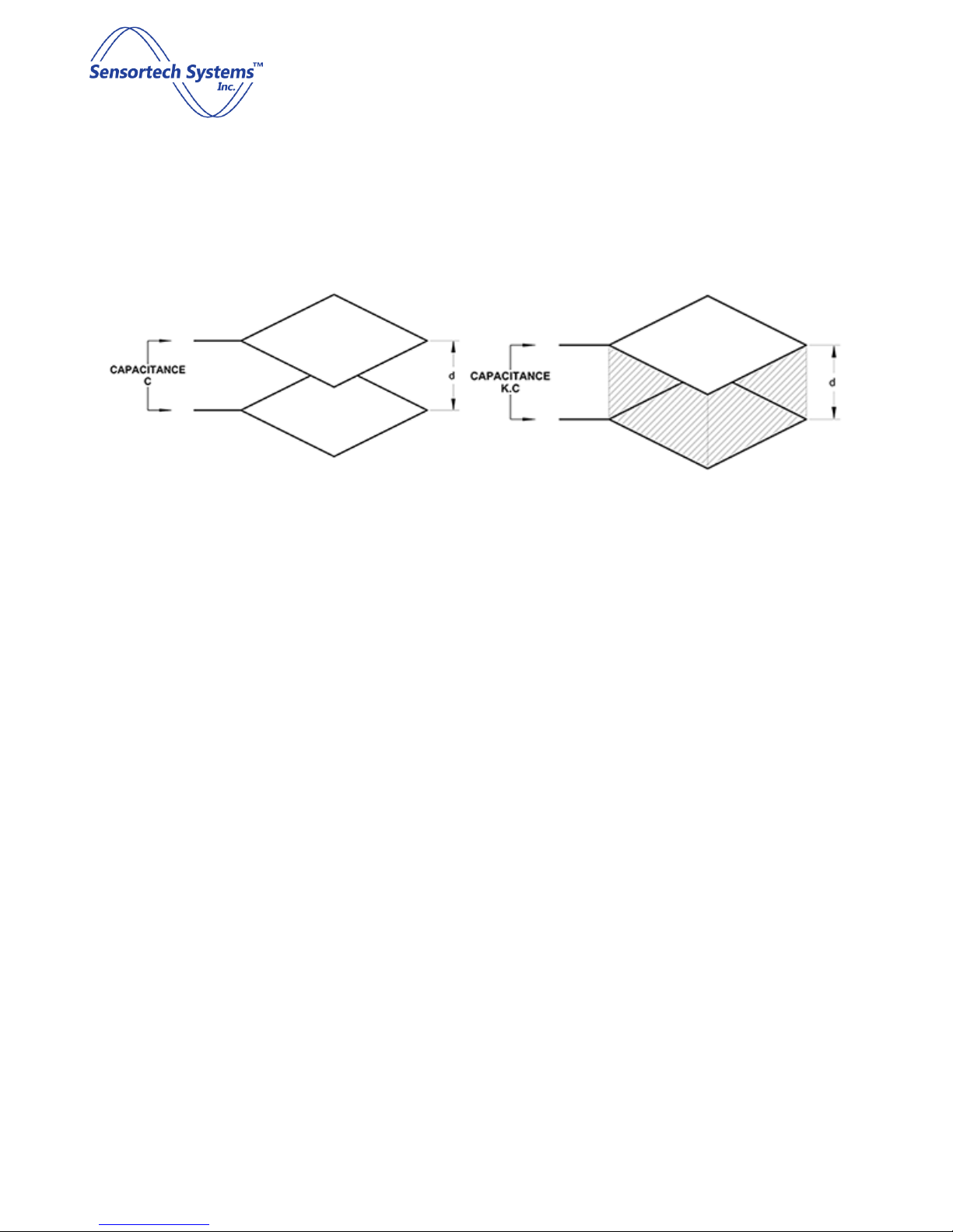
Figure 4: Parallel Plate Capacitor with Air Medium
Figure 5: Parallel Plate Capacitor with Dielectric Medium
As previously stated, dielectric is a material property affecting the way it ehaves in an electric field. A parallel
plate capacitor is shown in figure 2(a). If the medium separating the plates is air or a vacuum, the capacitance is
given y:
C = (ε
o
⋅ A) / d
where:
ε
o
= permitivitty of free space = 8.854 x 10
-12
A = Area of plate
d = separation distance of plates
When a dielectric medium separates the plates as in figure 2( ), capacitance ecomes:
C = (ε
o
⋅ ε
r
⋅ A) / d
where:
ε
r
= dielectric constant
Thus, capacitance is directly proportional to the dielectric constant of the material in the electric field.
C = K ⋅ ε
r
Parallel plate capacitance Sensors are rarely used for industrial applications; single-sided Sensors eing
preferred.

ST-3300 Smart RF Sensor Technical Manual
Screen 12 of 60
© Sensortech Systems, Inc. 2016
Figure 6: Parallel Plate Capacitor Showing Flux Lines
Figure 7: Planar Sensor Antenna Showing Flux Lines
Figure 6 is schematic representation of a parallel plate capacitor showing uniform electric flux lines except at the
edges where fringing occurs. The fringe field is generally undesira le in a capacitor, ut in a single-sided
capacitance Sensor, it is the only useful field.
Figure 7 is a cross-sectional view of a planar Sensor, most frequently used for gypsum oard applications. A
central element propagates an electric field to the grounded side plates. A small proportion of the field is
directly etween electrodes, ut most is the fringe field used to penetrate the oard. Figure 8 shows an example
of an Open Frame Planar Sensor Antenna.
Figure : Example of an Open Frame Planar Sensor Antenna
Electrically, the Sensor Antenna, is simply a capacitor. The electrical analogy of the gypsum product is itself a
capacitance with parallel resistance. The resistance or conductance represents the ionic conductance or
dielectric loss in the oard.
ST-3300 Smart RF Sensor Technical Manual
Screen 13 of 60
© Sensortech Systems, Inc. 2016
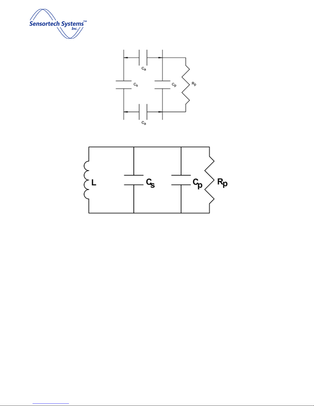
Figure 9: Electrical Schematic of Product Coupling
Figure 10: Electrical Schematic of Equivalent Resonant Circuit
Figure 9 shows the electrical schematic of the product coupled to the capacitive Sensor. Air gap capacitance (C
a
)
couples the product (C
p
) to the Sensor (C
s
) and must, therefore, e kept constant. Mounting the Sensor
etween conveyor rollers, spaced perhaps 6mm elow the plane of the rollers, ensures a constant coupling
capacitance, provided rollers are reasona ly true. The capacitances may e com ined as one (C
T
) which, while
mathematically incorrect, may simplistically e represented as C
T
= C
s
+ C
p
.
Figure 10 illustrates the resonant network formed y Sensor capacitance in parallel with product capacitance
also in parallel with inductor (L). This network has a unique resonant frequency at which inductive reactance
cancels capacitive reactance and network impedance is at a maximum. Impedance at resonance is actually
resistance (R
p
).
ST-3300 Smart RF Sensor Technical Manual
Screen 14 of 60
© Sensortech Systems, Inc. 2016
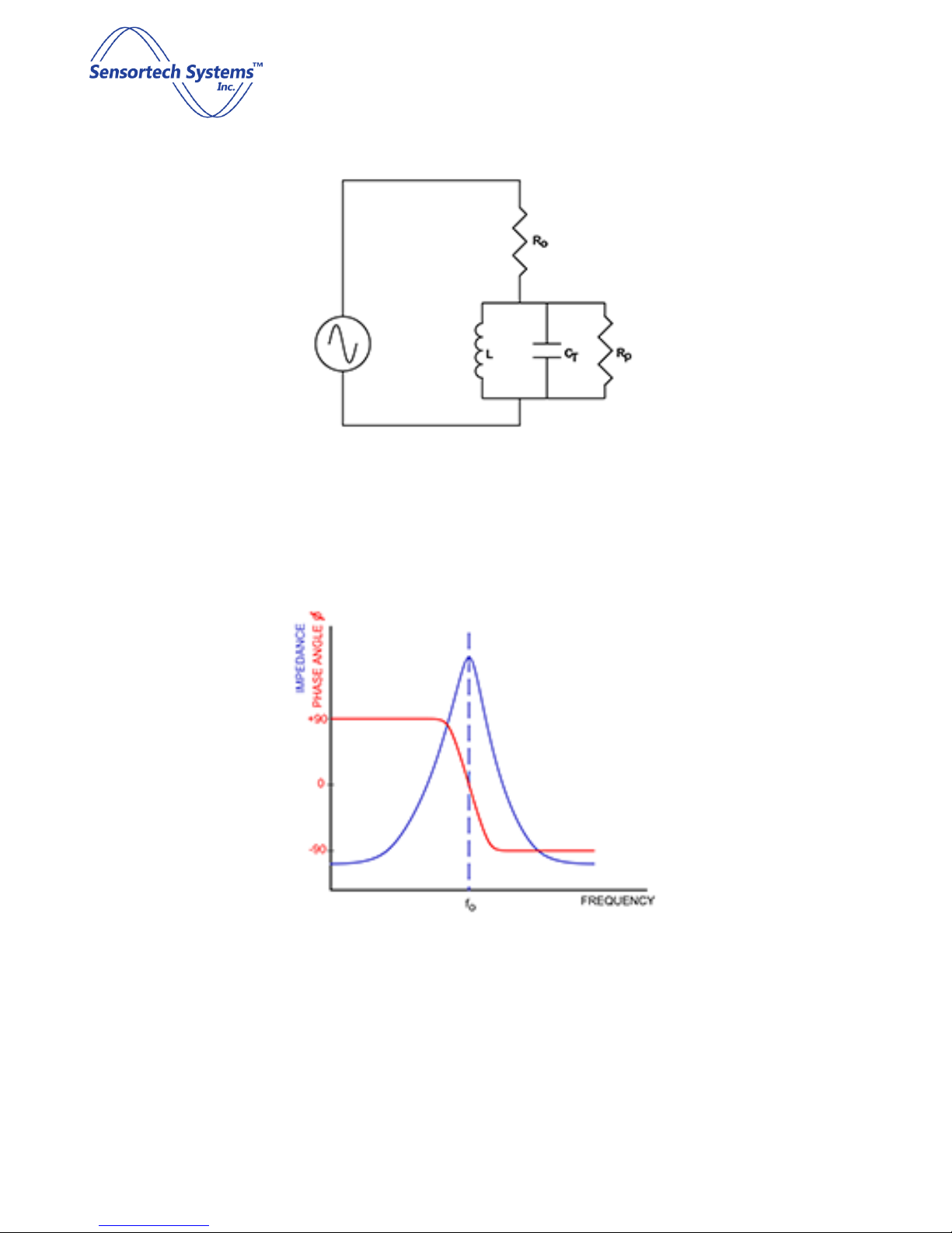
Figure 11: Electrical Schematic Example of a Resonant Circuit
Figure 12: Frequency, Phase and Impedance relationships of Resonant Network

ST-3300 Smart RF Sensor Technical Manual
Screen 15 of 60
© Sensortech Systems, Inc. 2016
The resonant network is driven from a suita le RF signal through a pure fixed resistor (R
o
) as shown in Figure 11.
As frequency increases, the network is first of all inductive with a leading phase angle. At resonance all reactive
components cancel and the circuit is purely resistive. At resonance, the signal amplitude across the resonant
network is a function of only R
o
, R
p
and amplitude of the driving signal. R
o
and R
p
ehave as a simple potential
divider.
Using a precision phase lock loop to adjust signal frequency to maintain zero phase angle across resistor R
o
ensures the network is always at resonance.
Resonant frequency is defined as:
f
o
= 1 / [2π√(L ⋅ C
T
)]
The Sensor measures this frequency and a proprietary measurement algorithm com ines Sensor frequency with
two reference frequencies to produce a dielectric value that is essentially independent of am ient temperatures
and component aging.
The resulting raw dielectric can e seen to e a function of Sensor capacitance (with product) and precision
reference capacitors. Inductance and stray capacitance are eliminated.
Moisture is directly proportional to the raw dielectric.
Given a linear relationship, the instrument can now e cali rated from analytical data to fit a linear function of
the form:
Moisture = a ⋅ D + b
Since capacitance C
T
is a composite of oth the Sensor and the product, it is necessary to remove the influence
of Sensor capacitance. This is achieved y measuring Sensor capacitance when no product is present (D
z
) and
su tracting this from future measurement in a similar way to performing a tare on a weigh scale. This action is
termed 'Pre-zero' and should e performed periodically to compensate for antenna changes and product uild-
up on the antenna.
The primary moisture measurement of the Sensor uses the principle of dielectric determination. Since moisture
has a much higher relative dielectric than most solids, it is possi le to relate to moisture content. Radio
frequency moisture determination, which is a penetrating measurement, has to take into account the mass of
the product eing measured in order to provide a percentage measurement. This is ecause the Sensor
effectively counts the water molecules within the Sensor field. If more product is squeezed into that field, it will
produce a higher moisture reading, even though the percentage water figure may e constant. In order to
correct for this, the product mass, weight or density must e taken into consideration.

ST-3300 Smart RF Sensor Technical Manual
Screen 16 of 60
© Sensortech Systems, Inc. 2016
Open Frame Planar Sensor Antenna Measurement
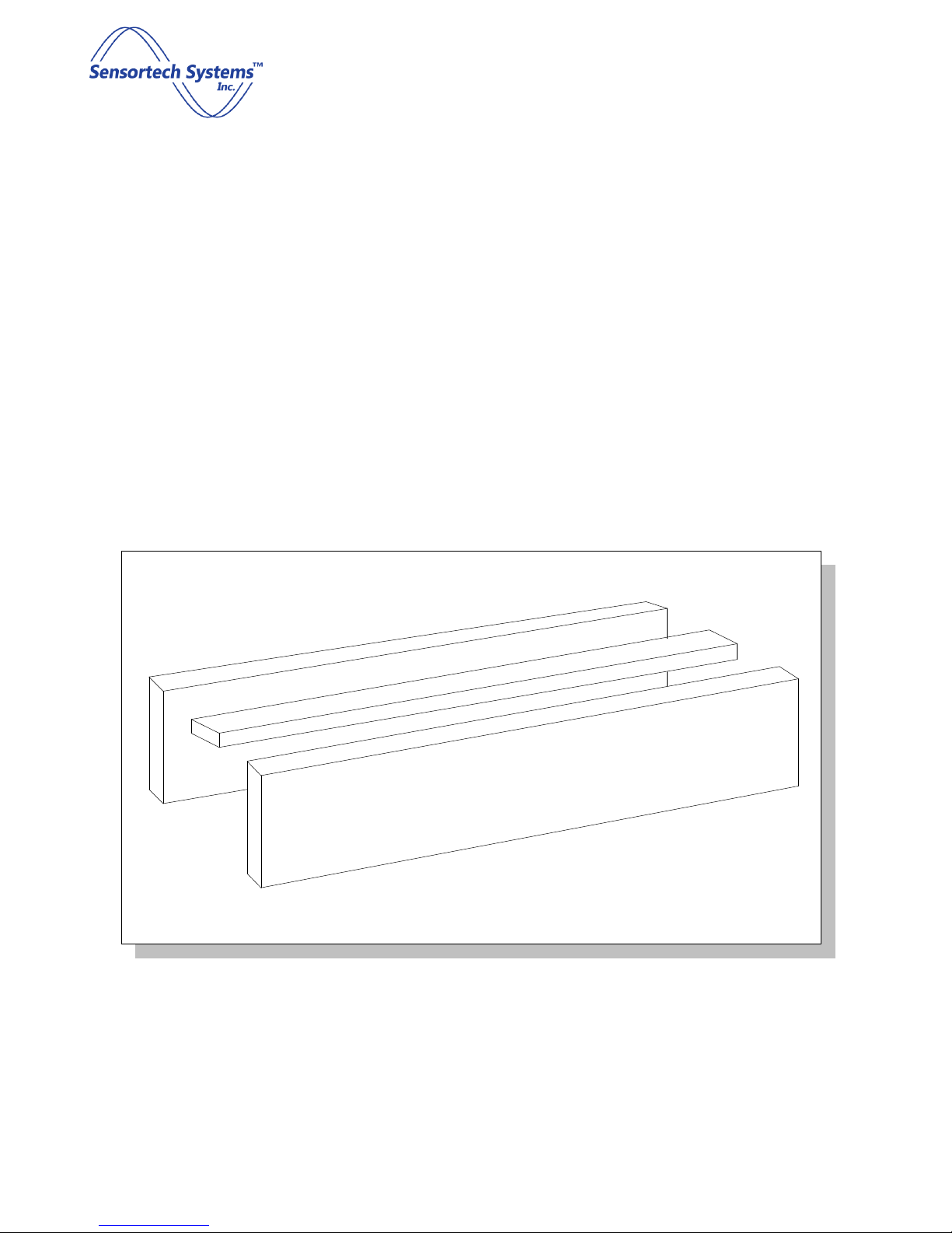
Figure 13: Open Frame Sensor - Radio Frequency Field Penetrating Through Product
The Figure 13 shows the typical radio electric field passing through a product. The dielectric effect of the product
will e a function of its dielectric constant and the length of flux paths passing through the product (fringe field
lines). The latter will e a function of product thickness and distance from the Sensor. If a parallel plate Sensor
were used, the field lines would e uniform and a dou ling in product thickness would produce a dou ling in
dielectric. The Sensor shown is a single sided or Planar Sensor Antenna, with a non-linear field. Dou ling of
product thickness will cause an increase in dielectric, ut not y a factor of two. A Planar Sensor Antenna
response would e of the form:
Sensor Measurement = Product Dielectric * (Mass)Kw
where:
Mass = weight, density, thickness etc.
Kw = coefficient determined y antenna geometry (less than 1)
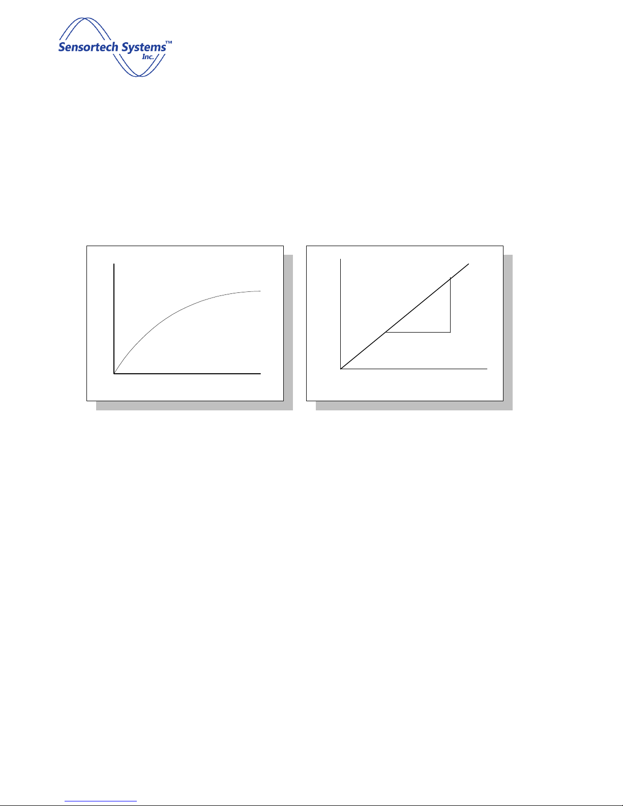
The value of Kw coefficient will depend upon antenna geometry, product presentation and form of mass
measurement e.g. thickness, weight etc. To determine Kw, a constant moisture product of varying mass is
presented to Sensor. A graph of log (Sensor response) vs. log (mass) must e plotted. Kw is given y the slope of
this line (see Figure 14).
Doc
ume
nt
product
dielectric
Doc
ume
nt
fringe field
air
dielectric
ST-3300 Smart RF Sensor Technical Manual
Screen 17 of 60
© Sensortech Systems, Inc. 2016
The product dielectric is coupled to the antenna via an interface such as air. In some cases, direct contact may
e made, or a fixed interface such as a Teflon or Ceramic window may isolate the Sensor from the product. The
important thing is that the interface etween product and Sensor, must remain constant in order for the
interface dielectric to e cancelled out of the product measurement. In the case of direct contact or a window,
this would e the case. If an air gap exists etween product and Sensor and the air gap distance varies, due to
mechanical vi ration or oard ounce, the total dielectric for the measurement will change. If the gap can e
measured, it can e compensated.
If the antenna were a point source, then the RF energy would decrease according to the inverse square law and
a simple compensation ased upon the square of the distance would e possi le. In practice the antenna is a
finite width radiator producing a more complex relationship. It is further complicated y field distortion through
the product.
Figure 13 shows the typical field pattern emanating from a planar electrode, ut this is somewhat idealized, as
the field is actually distorted or refracted within the product. The amount of distortion is a function of product
dielectric and is oth density and moisture dependent. This distortion will also affect the field in the air gap and
the distance relationship.
In practice, the product density usually remains fairly constant at a fixed point in the process, and the moisture
similarly should not vary too greatly. If this is the case, distance may e corrected y an equation of the form:
Compensated Sensor = product dielectric * (distance + Kd)2
If moisture and density are uncontrolled such as raw material measurement, it is etter to control or constrain
the distance variation rather than try to compensate for it.
Mass
Instrument
log (Mass)
log (Instrument)
Kw = log(y)/log(x)
y
x
Figure 14: Plots of Sensor Measurement vs. Product Mass

ST-3300 Smart RF Sensor Technical Manual
Screen 1 of 60
© Sensortech Systems, Inc. 2016
The example to the left shows three Sensor measurements of differing
moisture, at varying distances from the Sensor. No compensation is
applied and an inverse relationship is apparent.
. In this next example the same three Sensor measurements are
performed at varying distances. The Sensor has a compensation
equation:
Mc = Mu (D + 0.14)2
The offset coefficient Kd (.14) is determined y trial and error to o tain
flattest response.
0 .25 .50 .75
5
10
15
20
Distance
0 .25 .50 .75
10
30
40
50
Distance
20
Figure 15: Plot of Sensor
Measurement vs. Product
Distance
ST-3300 Smart RF Sensor Technical Manual
Screen 19 of 60
© Sensortech Systems, Inc. 2016
Sensor Antenna Design
From an electronic standpoint, antenna is a misnomer. A truer description would e electrode or
pro e, since antennae tend to denote devices designed for maximum propagation efficiency, usually
achieved y standing wave theory.
For dielectric measurement, standing waves are to e avoided at all cost since this would produce non-
uniform energy distri ution. The Sensortech Systems pro e is essentially a deli erately mismatched
antenna to provide road and uniform dielectric coupling to product.
Antenna geometry (shape, size, etc.) is mainly a function of application, since provided the a ove
criteria are met, it is largely a matter of mechanical design as how est to couple to the product.
Sensortech Systems, Inc. has over a period of years, developed many unique electrode designs
including: parallel plate, planar, cylindrical (pipeline), pro e and co-axial types. The most widely used
style is the planar type shown in figure 2. Consisting of a central electrode etween two ground planes,
or multiple electrodes interspersed with ground plane, this style provides a single sided measurement
preferred in most industrial applications.
Figure
16
: Planar Open Frame Sensor Antenna

ST-3300 Smart RF Sensor Technical Manual
Screen 20 of 60
© Sensortech Systems, Inc. 2016
Theory of Operation
Radio Fre uency Dielectric Measurement
Figure 17:Electric field interaction with an atom under the classical dielectric model
In the classical approach to the dielectric model a material is made up of atoms. The atoms consist of a positive
point charge at the center surrounded y a cloud of negative charge. The cloud of negative charge is ound to
the positive point charge. The atoms are separated y enough distance such that they do not interact with one
another. This is represented y the top left of the figure aside. Note: Remember the model is not attempting to
say anything about the structure of matter. It is only trying to describe the interaction between an electric field
and matter.
In the presence of an electric field the charge cloud is distorted, as shown the top right of Figure 17 a ove.
This can e reduced to a simple dipole using the superposition principle. A dipole is characterized y its dipole
moment. This is a vector quantity and is shown as the lue arrow la eled M. It is the relationship between the
electric field and the dipole moment that gives rise to the behavior of the dielectric. Note: The dipole moment
is shown to be pointing in the same direction as the electric field. This isn't always correct, but it is a major
simplification, and it is suitable for many materials.
When the electric field is removed the atom returns to its original state.
Other manuals for ST-3300 Series
1
Table of contents
Other Sensortech Systems Accessories manuals


Popular Accessories manuals by other brands

Baumer
Baumer Clever Level LBFH operating instructions

Amphenol
Amphenol Temposonics GB SSI Series Operation manual

Indel B
Indel B BREEZE T30 PV Instructions for use

Hach
Hach POLYMETRON 8398 user manual

PilotAware
PilotAware OGN-R manual

Delta Electronics
Delta Electronics CANopen Communication Module DVPCOPM-SL Applications manual


Insignia
Insignia NS-BC115SS9 user guide

HY Technologies
HY Technologies HYT-F4R4-L user manual

V-TAC
V-TAC Merrytec MK054V RC Series Installation instruction

AirMagnet
AirMagnet AM-5020-11AG user guide

elobau
elobau 424A Translation of original assembly instructions

MELINERA
MELINERA HG01082A Assembly, operating and safety instructions