Use individual 3/4" (20 mm) rigid conduit for the entire installed length of the sensor cable,
taking care to ensure that all embedded or outdoor couplings and terminations are made
expansion or control joints. For sensors embedded in slab on grade, conduit should be
depressed under these joints, as necessary.
unswitched 24 VAC power supply is connected across red and black wires
the grounded conductor. Output relay NO contact connections are made via the two relay
After wiring the sensor, kneed the supplied duct sealant till pliable. Pack duct sealant into the
sensor housing leaving enough space for the sensor electronics and wiring. Prope
the duct sealant will minimize the accumulation of water and ice in the housing and protect
the sensor against possible ice damage. Refer back to Figure 1.
Next, place wiring and electronics into the housing. Check for alignment between the sens
and pavement surfaces. If the sensor and pavement are not aligned, remove sensor from
Use individual 3/4" (20 mm) rigid conduit for the entire installed length of the sensor cable,
taking care to ensure that all embedded or outdoor couplings and terminations are made
expansion or control joints. For sensors embedded in slab on grade, conduit should be
depressed under these joints, as necessary.
-
unswitched 24 VAC power supply is connected across red and black wires
the grounded conductor. Output relay NO contact connections are made via the two relay
res without discrimination. These are white, green, yellow, orange, or blue.
After wiring the sensor, kneed the supplied duct sealant till pliable. Pack duct sealant into the
sensor housing leaving enough space for the sensor electronics and wiring. Prope
the duct sealant will minimize the accumulation of water and ice in the housing and protect
the sensor against possible ice damage. Refer back to Figure 1.
Next, place wiring and electronics into the housing. Check for alignment between the sens
and pavement surfaces. If the sensor and pavement are not aligned, remove sensor from
Use individual 3/4" (20 mm) rigid conduit for the entire installed length of the sensor cable,
taking care to ensure that all embedded or outdoor couplings and terminations are made
expansion or control joints. For sensors embedded in slab on grade, conduit should be
depressed under these joints, as necessary.
furnished with 60’ (18.29m) 4
unswitched 24 VAC power supply is connected across red and black wires
the grounded conductor. Output relay NO contact connections are made via the two relay
res without discrimination. These are white, green, yellow, orange, or blue.
After wiring the sensor, kneed the supplied duct sealant till pliable. Pack duct sealant into the
sensor housing leaving enough space for the sensor electronics and wiring. Prope
the duct sealant will minimize the accumulation of water and ice in the housing and protect
the sensor against possible ice damage. Refer back to Figure 1.
Next, place wiring and electronics into the housing. Check for alignment between the sens
and pavement surfaces. If the sensor and pavement are not aligned, remove sensor from
Use individual 3/4" (20 mm) rigid conduit for the entire installed length of the sensor cable,
taking care to ensure that all embedded or outdoor couplings and terminations are made
re conduit with other wiring. Do not route conduit across pavement
expansion or control joints. For sensors embedded in slab on grade, conduit should be
depressed under these joints, as necessary.
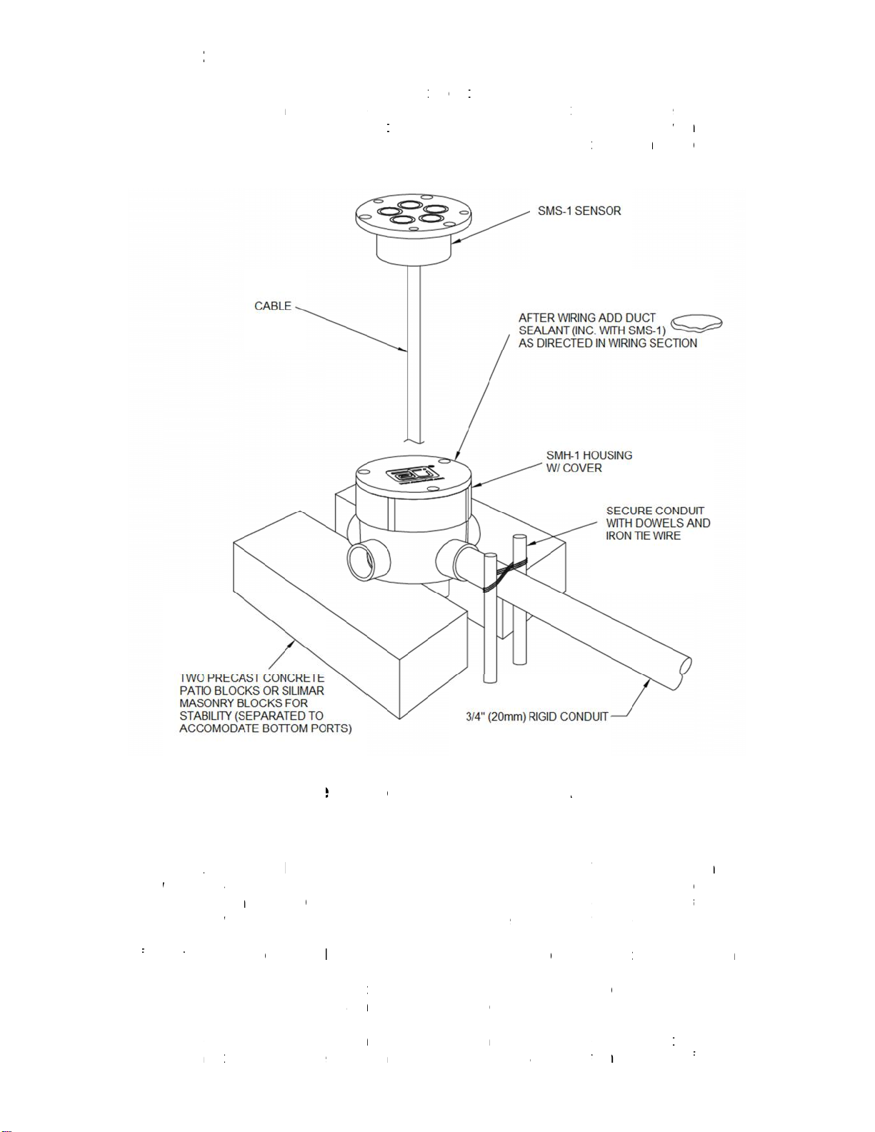
Figure 1. INSTALLATION DIAGRAM.
furnished with 60’ (18.29m) 4
unswitched 24 VAC power supply is connected across red and black wires
the grounded conductor. Output relay NO contact connections are made via the two relay
res without discrimination. These are white, green, yellow, orange, or blue.
After wiring the sensor, kneed the supplied duct sealant till pliable. Pack duct sealant into the
sensor housing leaving enough space for the sensor electronics and wiring. Prope
the duct sealant will minimize the accumulation of water and ice in the housing and protect
the sensor against possible ice damage. Refer back to Figure 1.
Next, place wiring and electronics into the housing. Check for alignment between the sens
and pavement surfaces. If the sensor and pavement are not aligned, remove sensor from
Use individual 3/4" (20 mm) rigid conduit for the entire installed length of the sensor cable,
taking care to ensure that all embedded or outdoor couplings and terminations are made
re conduit with other wiring. Do not route conduit across pavement
expansion or control joints. For sensors embedded in slab on grade, conduit should be
depressed under these joints, as necessary.
Figure 1. INSTALLATION DIAGRAM.
furnished with 60’ (18.29m) 4
-
conductor jacketed #18 AWG field leads. The
unswitched 24 VAC power supply is connected across red and black wires
the grounded conductor. Output relay NO contact connections are made via the two relay
res without discrimination. These are white, green, yellow, orange, or blue.
After wiring the sensor, kneed the supplied duct sealant till pliable. Pack duct sealant into the
sensor housing leaving enough space for the sensor electronics and wiring. Prope
the duct sealant will minimize the accumulation of water and ice in the housing and protect
the sensor against possible ice damage. Refer back to Figure 1.
Next, place wiring and electronics into the housing. Check for alignment between the sens
and pavement surfaces. If the sensor and pavement are not aligned, remove sensor from
Use individual 3/4" (20 mm) rigid conduit for the entire installed length of the sensor cable,
taking care to ensure that all embedded or outdoor couplings and terminations are made
re conduit with other wiring. Do not route conduit across pavement
expansion or control joints. For sensors embedded in slab on grade, conduit should be
Figure 1. INSTALLATION DIAGRAM.
conductor jacketed #18 AWG field leads. The
unswitched 24 VAC power supply is connected across red and black wires
the grounded conductor. Output relay NO contact connections are made via the two relay
res without discrimination. These are white, green, yellow, orange, or blue.
After wiring the sensor, kneed the supplied duct sealant till pliable. Pack duct sealant into the
sensor housing leaving enough space for the sensor electronics and wiring. Prope
the duct sealant will minimize the accumulation of water and ice in the housing and protect
Next, place wiring and electronics into the housing. Check for alignment between the sens
and pavement surfaces. If the sensor and pavement are not aligned, remove sensor from
Use individual 3/4" (20 mm) rigid conduit for the entire installed length of the sensor cable,
taking care to ensure that all embedded or outdoor couplings and terminations are made
re conduit with other wiring. Do not route conduit across pavement
expansion or control joints. For sensors embedded in slab on grade, conduit should be
conductor jacketed #18 AWG field leads. The
the grounded conductor. Output relay NO contact connections are made via the two relay
res without discrimination. These are white, green, yellow, orange, or blue.
After wiring the sensor, kneed the supplied duct sealant till pliable. Pack duct sealant into the
the duct sealant will minimize the accumulation of water and ice in the housing and protect
Next, place wiring and electronics into the housing. Check for alignment between the sens
and pavement surfaces. If the sensor and pavement are not aligned, remove sensor from
Use individual 3/4" (20 mm) rigid conduit for the entire installed length of the sensor cable,
taking care to ensure that all embedded or outdoor couplings and terminations are made
re conduit with other wiring. Do not route conduit across pavement
expansion or control joints. For sensors embedded in slab on grade, conduit should be
conductor jacketed #18 AWG field leads. The
the grounded conductor. Output relay NO contact connections are made via the two relay
After wiring the sensor, kneed the supplied duct sealant till pliable. Pack duct sealant into the
the duct sealant will minimize the accumulation of water and ice in the housing and protect
Next, place wiring and electronics into the housing. Check for alignment between the sens
and pavement surfaces. If the sensor and pavement are not aligned, remove sensor from
Use individual 3/4" (20 mm) rigid conduit for the entire installed length of the sensor cable,
taking care to ensure that all embedded or outdoor couplings and terminations are made
re conduit with other wiring. Do not route conduit across pavement
conductor jacketed #18 AWG field leads. The
the grounded conductor. Output relay NO contact connections are made via the two relay
After wiring the sensor, kneed the supplied duct sealant till pliable. Pack duct sealant into the
the duct sealant will minimize the accumulation of water and ice in the housing and protect
Next, place wiring and electronics into the housing. Check for alignment between the sens
and pavement surfaces. If the sensor and pavement are not aligned, remove sensor from
2
After wiring the sensor, kneed the supplied duct sealant till pliable. Pack duct sealant into the


