SIL GTIS Power Systems Villager III User manual

Introduction
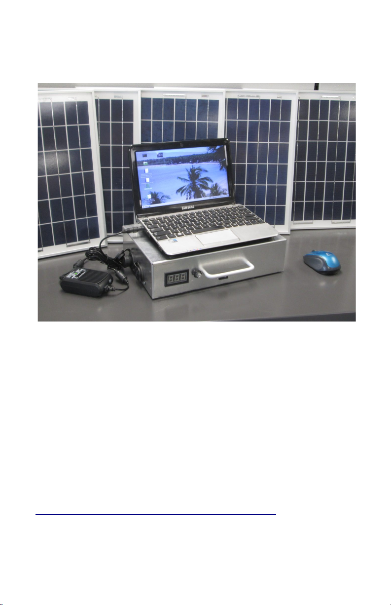
Villager III powering a convertible tablet with a DC-DC adapter
The Villager III Power Bank provides 12-volts dc power
at up to 145 watts from both sockets combined. The
optional Vanson DC-DC converter supplies 5 V on a USB
connector for charging tablets and cell phones, and can also
provide 15 V to 24 V regulated DC for laptops, BGANs, etc.
The Villager III can store 216 watthours of energy. Your
repeating daily loads should be about 100 watthours or less,
which is sufficient to run a netbook or ultrabook computer for
8 hours plus it’s built-in 2 W LED strip in the evening. See
http://www.powermon.org/store/archives/1393 for an
explanation of watthours and estimates of watthours needed
for various electronics, and how to estimate the solar panel
size you need.
Charging
Usually a 50 to 100 watt solar panel is used to charge
the Villager III, depending on the user's loads.
120 watts is the maximum recommended solar panel
size. Panels larger than 120 W will shorten the battery
lifetime and panels over 145 W could destroy the charge
controller. Solar panels should be of the “12-volt” type, with
an open circuit voltage (Voc) between 19 V and 24 V.
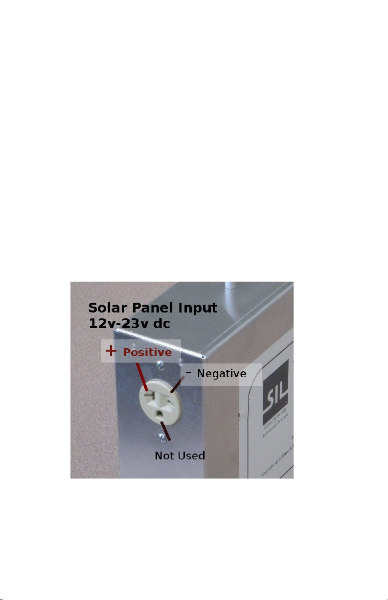
GTIS Power Systems can supply you with the correct
connector (NEMA 6-15P) for the solar panel. Proper polarity
for the solar panel connector is shown below (the T-slot is
positive; the flat slot is negative; the ground slot is not used).
Accidentally reversing solar panel polarity will prevent
charging, but will not damage the panels or Villager III.
Figure 2: View showing solar panel input
You can tell if your panels are producing power by
watching the voltmeter before and after you plug in the solar
panels. The voltage should immediately increase by 0.1 V
or 0.2 V when the panels are connected.

Using the Villager III
The On-Off toggle switch (A) must be in the “On”
position for the Villager III to operate. Turn it “Off” only for
transport or long term storage.
View showing 12 V outputs and controls
There are two 12-volt output sockets (D) that may be
used to charge devices. You may plug in any DC adapter or
inverter designed for automotive use, however, do not
exceed 145 watts of load.
The voltmeter (C) will show the battery voltage
whenever the 2W LED strip light is lit by pushing the
“Meter/LED Light” button (B). The meter can be used for
troubleshooting or to estimate the charge level of the Villager
III (See Appendix A).

The indicator LED (E), if present, indicates system
status and gives a rough indication of the Villager III battery
charge level. (See replica of the label below.) If the system
has shut down due to low voltage, the LED will blink orange
slowly. You must recharge the batteries.
In an overload condition, the status LED (E) will flash
orange rapidly and output power will cut off. This means the
loads are exceeding 145 W. The Villager III will try to restart
after a 12-second delay. Unplug all loads and check to
make sure there are no short circuits in the system. If the
overload is not removed quickly, the Villager III will try to
restart every 15 minutes. You can speed this up by turning
off the main on-off switch and turning it back on after
correcting the overload condition.
Some Villager-III units, with a SS designation on the
end of their serial number, do not have an indicator light.
You can use the built-in meter to determine the charge level.
(See appendix A) When you have depleted the battery to the
Low Voltage disconnect point the voltmeter and LED strip
will no longer light up, indicating you need to recharge it. An
overload will also extinguish the meter and LED, but will
automatically reset one minute after removing the overload.
Figure 4: LED indicator label

Storage
The batteries in the Villager III keep best in a partially
charged state while in storage. Run the batteries partially
down to a resting voltage of 13.0 V to 13.2 V and turn off the
rocker switch.
Recharge and partially discharge the batteries every six
months.
Store the Villager III at temperatures below 35°C
(95°F).
Testing After Prolonged Storage
If your Villager III is left in storage without recharging for
over a year, especially if at high temperatures, you should
test each of the three internal batteries individually before
using it.
Have a technician remove the batteries and charge
each one individually on a test bench at <2 amperes until the
battery voltage reaches 14.2 V. A flameproof container and
ventilated area are recommended since there is a small
chance a bad cell could burst and even ignite, but this is
very unlikely.
Discharge each battery to 12.0 V and recharge all
three batteries to 14.2 V before reassembling them into the
Villager III. The electronic “BMS” board inside each battery
should stop the charge or discharge cycle if there are
internal problems with any of the cells. In that case the
battery is bad and needs replacing. Contact

Precautions
Water
The Villager III is not waterproof. Do not leave it
outdoors in the rain or immerse it in water. If water gets
inside the case, turn off the toggle switch and allow the
Villager III to dry thoroughly before using it.
Heat
Cooler temperatures will improve the lifetime of the
batteries and electronics. Whenever possible, avoid leaving
the Villager III in hot locations or in direct sunlight.
Battery Failure
The Villager III contains three separate LiFePO4 smart
battery packs. When one of the batteries gets old and fails,
its internal electronics board will prevent it from charging or
discharging, resulting in sharply reduced capacity for the
Villager III. When one fails, all three batteries should be
replaced at the same time. Do not attempt to bypass the
circuit board inside the battery and force charge a failed
battery because it can catch on fire!
batteries or parts.

Appendix A
Voltmeter Readings
The values in the table below are estimates and will
vary depending on the accuracy of your meter, the size of
your loads, and the length of time the batteries have been
resting with no load or panel connected. Villager III display
meters may read as much as 0.2 volts lower or higher than
actual value.
% Charged Voltage
While
Charging
Voltage After
Discharging and
Resting 10 Min.
90% to 100% ≥13.7 V ≥13.3 V
About 75% 13.5 V 13.2 V to 13.3 V
About 50% 13.3 V 13.1 V
About 25% 13.1 V 12.9 V
Fully
Discharged
12.9 V 12.7 V
Appendix B
Maximum Wattages
Solar panel input – 120 watts (panel rating)
Combined DC output, both sockets – 145 watts
Optional Vanson DC-DC converter output – 100 watts
Table of contents


