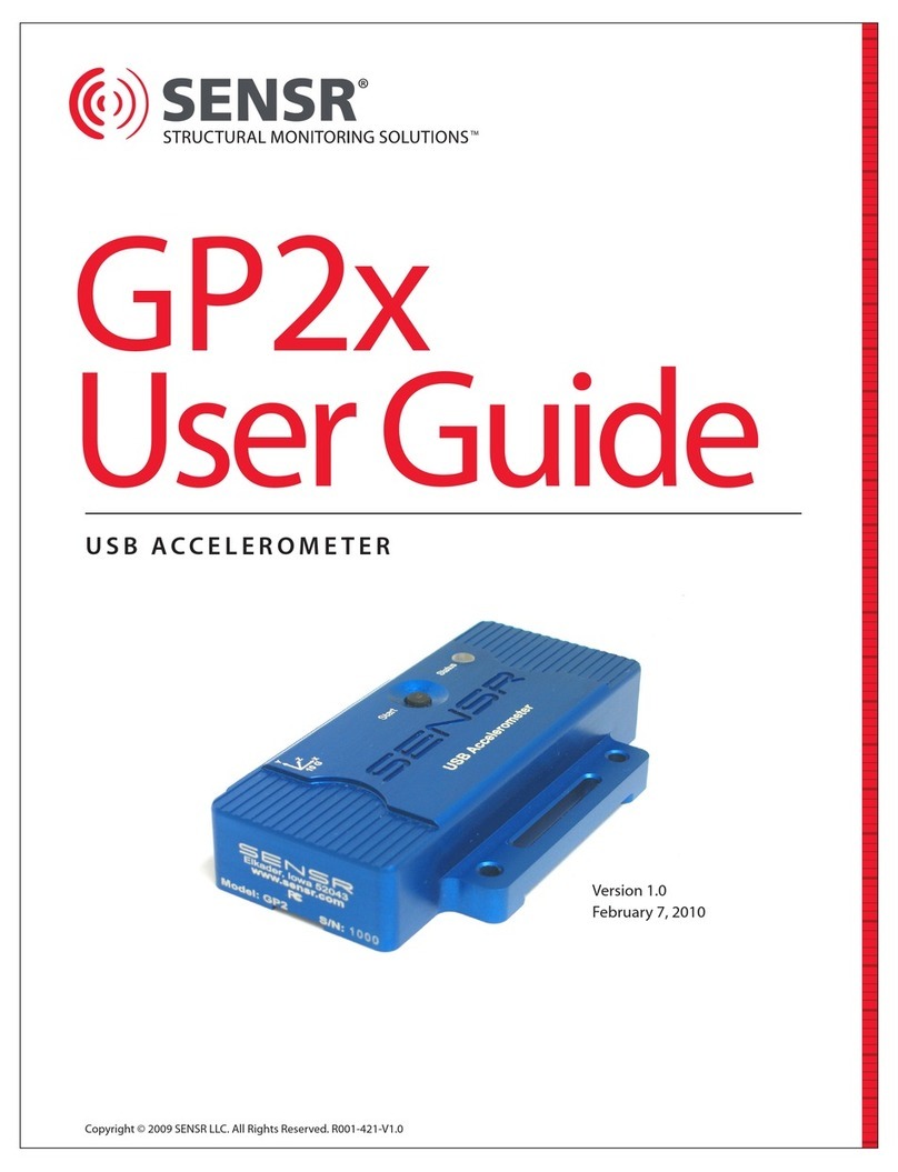
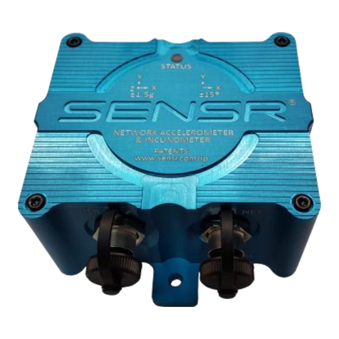
Sensr GP1 User manual

Copyright © 2007 Reference, LLC. All Rights Reserved.
PROGRAMMABLE ACCELEROMETER
GP1
User Guide
Version 2.2
August 27, 2007

GP1 USER GUIDE
TABLE OF CONTENTS
QUICK START GUIDE 5
BEFORE YOU BEGIN 6
1.1 Packing List 6
GETTING STARTED 6
2.1 Installing Batteries 6
2.2 Installing the Software 6
2.3 Connecting the Hardware 7
2.4 Launching the Software 9
2.5 Review the User Manual 9
2.6 Technical Support 9
GP1 USER GUIDE 10
1 PREAMBLE 11
1.1 FCC Statement 11
1.2 Software License Agreement 11
1.3 Acceptable Use 12
1.4 Safe Transport 13
2 GP1 PROGRAMMABLE ACCELEROMETER 13
2.1 General 13
2.2 Specications 13
2.3 Acceleration Ranges 13
2.4 Data Recorder Mode 14
2.5 Event Recorder Mode 14
2.6 Real-Time Data Capture Mode 14
2.7 LED Status Indicator 15
2.8 Start Button 15
3 DATA RECORDER MEASUREMENTS AND FEATURES 15
3.1 Maximum Axis Acceleration 15
3.2 Minimum Axis Acceleration 15
3.3 Average Axis Acceleration 15
3.4 Axis Threshold Counter 16
2

GP1 USER GUIDE
TABLE OF CONTENTS continued
3.5 Vector Magnitude (VM) Max 16
3.6 Vector Magnitude (VM) Average 16
3.7 Vector Magnitude Threshold Counter 16
3.8 Orientation 16
3.9 Near Zero G 16
3.10 Peak Duration 16
3.11 Temperature 17
3.12 Button Press 17
3.13 Alerts 17
4 EVENT RECORDER MEASUREMENTS 18
4.1 Axis Acceleration 18
4.2 Temperature 18
5 SYSTEM SETUP 19
5.1 Battery Information 19
5.2 Installing Batteries 19
5.3 Installing the Software 19
5.4 Connecting the GP1 20
6 SENSWARE 21
6.1 Sensware Description 21
6.2 Accessing Help 21
6.3 Using Sensware 21
6.4 Connecting to a GP1 22
6.5 Main Control Panel 23
6.6 Device Initialization 23
6.7 GP1 Init General 24
6.8 GP1 Init Data Recorder 25
6.9 GP1 Init Event Recorder 26
6.10 Downloading Data 27
6.11 Reviewing the Data 27
6.12 Device Information 30
6.13 Real Time Data Capture 31
3

GP1 USER GUIDE
TABLE OF CONTENTS continued
7 CONFIGURING THE DATA RECORDER 33
7.1 X Y Z Axis 33
7.1.1 X Y Z Axis Measurements 33
7.1.2 X Y Z Axis Settings 34
7.1.3 X Y Z Axis Alerts 35
7.2 Vector Magnitude 36
7.2.1 Vector Magnitude Measurements 36
7.2.2 Vector Magnitude Settings 37
7.2.3 Vector Magnitude Alerts 38
7.3 Orientation 39
7.3.1 Orientation Settings 39
7.3.2 Orientation Alerts 40
7.4 Near Zero G 41
7.4.1 Near Zero G Measurements 41
7.4.2 Near Zero G Settings 42
7.4.3 Near Zero G Alerts 43
7.5 Peak Duration 44
7.5.1 Peak Duration Settings 44
7.5.2 Peak Duration Alerts 46
7.6 Temperature 47
7.6.1 Temperature Alerts 47
7.7 Button Press 48
8 CONFIGURING THE EVENT RECORDER 49
9 SAVING DATA 50
10 EXPORTING DATA 50
11 MISCELLANEOUS 50
11.1 GP1 Maintenance 50
11.2 Technical Support 50
11.3 Product Warranty 50
4

GP1
Quick Start
Guide

QUICK START GUIDE
1 BEFORE YOU BEGIN
1.1 Packing List
Please conrm that you received a complete GP1 Programmable Accelerometer kit.
You should have received:
• 1 x GP1 Programmable Accelerometer
• 1 x USB Interface cable
• 2 x AA Batteries
• 1 x Sensware CD
2 GETTING STARTED
2.1 Installing Batteries
The GP1 Programmable Accelerometer is powered by two AA alkaline batteries. To install the batteries
you must remove the access cover (See Figure 1). The cover is secured to the housing by 2 quarter-turn
fasteners. Remove the cover by turning the fasteners counter-clockwise approximately ¼ of a turn.
Once the fastener disengages, it will pop up and you can lift the cover o of the housing. The SENSR GP1’s
battery box contains an embossed diagram that illustrates proper battery orientation; please consult
this diagram before installing the batteries.
6
Figure 1 Battery Access Cover
2.2 Installing the Software
Before installing the software take a moment and verify that the computer meets the following minimum
systems requirements:
• Operating System: Windows 2000 SP4 or Windows XP SP2
• CPU: Pentium 4, 2.00GHz
• System Memory (RAM): 512MB
• Hard Disk: 200MB free space
• Display: 1024 x 768, 32-bit “True Color”

QUICK START GUIDE
The software for the GP1 Programmable Accelerometer is based upon Microsoft’s .NET Framework.
You can download this environment from Microsoft using your Windows update utility.
Depending on your update settings you may need to select the Custom update option.
The .NET Framework 2.0 is considered an optional component and is listed in the Software category.
You must install the .NET Framework 2.0 before you install the Sensware application.
To install the Sensware application:
• Insert the CD into your CD/ DVD drive.
• Double-click your My Computer icon.
• Double-click your CD / DVD drive icon.
• Double-click the Sensware set -up icon (See Figure 2).
• Follow the installation wizard’s instructions.
7
Figure 2 Set-up icon
2.3 Connecting the Hardware
The Sensr GP1 Programmable Accelerometer communicates with your computer via USB. Connect the
supplied USB cable to your computer. The GP1 features an internal USB connector; you must remove
the access cover (See Figure 1) in order to connect the GP1. The cover is secured to the housing by
2 quarter-turn fasteners. Remove the cover by turning the fasteners counter-clockwise approximately
¼ of a turn, once the fastener disengages it will pop up and you can lift the cover o of the housing.
The GP1 has a mini-B USB connector that is located in a pocket between the battery box and the housing
(See Figure 3). Note that it is a keyed connector and you are required to align the USB cable before
plugging it in.
Figure 3. Mini-B Connector

QUICK START GUIDE
To install the GP1 hardware, rst plug the USB cable into the USB connector on the GP1 and into an
available USB connector on the computer.
8
You should see an indication near the system tray that the computer has detected new hardware.
A moment later, a dialog will appear for the Found New Hardware Wizard. Do not allow the wizard
to connect to Windows Update to search for software. Click the Next button.
Allow the wizard to install the software automatically. If the wizard cannot nd the correct software,
you can install from a specic location, which is the root of the CD-ROM. Click the Next button.

QUICK START GUIDE
A warning will appear to advise you that the software has not passed Windows Logo testing.
This is not a problem. Click the Continue Anyway button.
When the wizard is nished, this dialog appears. Click the Finish button.
You should see an indication near the system tray that the computer has nished installing the hardware.
9
2.4 Launching the Software
To launch Sensware select Start>Programs>Sensware
2.5 Review the User Manual
We recommend that you review the User’s Manual; the manual can be found under the Help menu.
2.6 Technical Support
If you have any questions about the product or require technical support please email us at
support@sensr.com or call 563.245.3750.

USER GUIDE
GP1
User
Guide

GP1 USER GUIDE
1 PREAMBLE
1.1 FCC Statement
This device complies with Part 15 of the FCC rules. Operation is subject to the following two conditions:
• This device may not cause harmful interference.
• This device must accept any interference received, including interference that may cause
undesirable operation.
1.2 Software License Agreement
PLEASE READ THIS SOFTWARE LICENSE AGREEMENT CAREFULLY BEFORE USING THE SOFTWARE.
License Grant: Reference LLC. (“Reference”) and its suppliers grant to Customer (“Customer”) a nonexclusive
and nontransferable license to use the Sensware software (“Software”) in object code form only on as
many central processing units as is required to support the functionality of the products used in
conjunction with this software.
EXCEPT AS EXPRESSLY AUTHORIZED ABOVE, CUSTOMER SHALL NOT: COPY, IN WHOLE OR IN PART,
SOFTWARE OR DOCUMENTATION; MODIFY THE SOFTWARE; REVERSE COMPILE OR REVERSE ASSEMBLE
ALL OR ANY PORTION OF THE SOFTWARE; OR RENT, LEASE, DISTRIBUTE, SELL, OR CREATE DERIVATIVE
WORKS OF THE SOFTWARE.
Customer agrees that aspects of the licensed materials, including the specic design and structure of
individual programs, constitute trade secrets and/or copyrighted material of Reference. Customer agrees
not to disclose, provide, or otherwise make available such trade secrets or copyrighted material in any
form to any third party without the prior written consent of Reference. Customer agrees to implement
reasonable security measures to protect such trade secrets and copyrighted material. Title to Software
and documentation shall remain solely with Reference.
SOFTWARE WARRANTY. Reference warrants that for a period of ninety (90) days from the date of shipment
from Reference: (i) the media on which the Software is furnished will be free of defects in materials and
workmanship under normal use; and (ii) the Software substantially conforms to its published specications.
Except for the foregoing, the Software is provided AS IS. This limited warranty extends only to Customer as
the original licensee. Customer’s exclusive remedy and the entire liability of Reference under this limited
warranty will be, at Reference’s option, repair, replacement, or refund of the Software. In no event does
Reference warrant that the Software is error free or that Customer will be able to operate the Software
without problems or interruptions. This warranty does not apply if the software (a) has been altered, except
by Reference, (b) has not been installed, operated, repaired, or maintained in accordance with instructions
supplied by Reference.
DISCLAIMER. EXCEPT AS SPECIFIED IN THIS WARRANTY, ALL EXPRESS OR IMPLIED CONDITIONS,
REPRESENTATIONS, AND WARRANTIES INCLUDING, WITHOUT LIMITATION, ANY IMPLIED WARRANTY
OF MERCHANTABILITY, FITNESS FOR A PARTICULAR PURPOSE,
11

GP1 USER GUIDE
NON-INFRINGEMENT OR ARISING FROM A COURSE OF DEALING, USAGE, OR TRADE PRACTICE, ARE HEREBY
EXCLUDED TO THE EXTENT ALLOWED BY APPLICABLE LAW. IN NO EVENT WILL REFERENCE BE LIABLE FOR
ANY LOST REVENUE, PROFIT, OR DATA, OR FOR SPECIAL, INDIRECT, CONSEQUENTIAL, INCIDENTAL, OR
PUNITIVE DAMAGES HOWEVER CAUSED AND REGARDLESS OF THE THEORY OF LIABILITY ARISING OUT
OF THE USE OF OR INABILITY TO USE THE SOFTWARE EVEN IF REFERENCE HAS BEEN ADVISED OF THE
POSSIBILITY OF SUCH DAMAGES. In no event shall Reference’s liability to Customer, whether in contract,
tort (including negligence), or otherwise, exceed the price paid by Customer. The foregoing limitations
shall apply even if the above-stated warranty fails of its essential purpose. SOME STATES DO NOT ALLOW
LIMITATION OR EXCLUSION OF LIABILITY FOR CONSEQUENTIAL OR INCIDENTAL DAMAGES.
The above warranty DOES NOT apply to any beta software, any software made available for testing or
demonstration purposes, any temporary software modules or any software for which Reference does
not receive a license fee. All such software products are provided AS IS without any warranty whatsoever.
This License is eective until terminated. Customer may terminate this License at any time by destroying
all copies of Software including any documentation. This License will terminate immediately without
notice from Reference if Customer fails to comply with any provision of this License. Upon termination,
Customer must destroy all copies of Software.
Software, including technical data, is subject to U.S. export control laws, including the U.S. Export
Administration Act and its associated regulations, and may be subject to export or import regulations
in other countries. Customer agrees to comply strictly with all such regulations and acknowledges that
it has the responsibility to obtain licenses to export, re-export, or import Software.
This License shall be governed by and construed in accordance with the laws of the State of Iowa,
United States of America, as if performed wholly within the state and without giving eect to the
principles of conict of law. If any portion hereof is found to be void or unenforceable, the remaining
provisions of this License shall remain in full force and eect. This License constitutes the entire
License between the parties with respect to the use of the Software.
1.3 Acceptable Use
The Sensr GP1 is a general-purpose instrument only, it is not recommended for any use that requires
critical measurement or precision triggering. The GP1 is not to be used for:
i) Critical testing
ii) Monitoring life support or patient diagnoses
iii) Any type of input or controller for any process or system including but not limited to:
a) Automated production or manufacturing
b) Life support or patient diagnosis
c) Vehicle or machine control
d) Emergency, redundant or backup systems
The GP1 is designed to be used in a protected environment and should not be exposed to liquids.
It is the responsibility of the user to conrm that any use of the product conforms with all country,
federal, state, county, municipal laws, ordinances and regulations, if any, applicable to the transport
and use of the GP1.
12

GP1 USER GUIDE
1.4 Safe Transport
As the manufacturer of the GP1, Reference, LLC, has contacted the United States Department
of Transportation in an eort to seek guidance and usage instructions for the GP1 for the user.
Reference, LLC, recommends the power source for the GP1 to be 2 x AA alkaline batteries.
The Department of Transportation has stated that there are no restrictions related to the use
of the GP1 following the recommending power source. The Department of Transportation has
cited the following notice for consideration when using an alternative power source for the unit.
DEPARTMENT OF TRANSPORTATION
Research and Special Programs Administration
[Docket No. RSPA-99-5143; Notice No. 99-8]
Advisory Guidance; Transportation of Batteries and Devices That Contain Batteries
AGENCY: Research and Special Programs Administration (RSPA), DOT.
ACTION: Advisory guidance.
2 GP1 PROGRAMMABLE ACCELEROMETER
2.1 General
The GP1 Programmable Accelerometer is a 3-axis motion recording instrument that allows the user
to monitor, record and evaluate: motions, impacts, shocks, drops, orientation and temperature.
2.2 Specications
Size: 3.935” x 2.560”x 1.140”
Weight With Batteries: 8.25 oz
Housing Material: 6061 - T6 Aluminum
Power: 2 x AA Alkaline Batteries
Battery Life: More than 40 Days
Connectivity: USB
Accelerometer Type: Programmable 3 Axis MEMS
Accelerometer Range: User programmable ±2.5g, ±3.3g, ±6.7g, ±10g
Frequency Response: DC - 45Hz
Sampling Rate: 100Hz per axis
Memory Type: Non-Volatile EEPROM
Memory Size: 1 Megabyte
Device Temperature Range: -20°C to +80°C
2.3 Acceleration Ranges
The GP1 incorporates a programmable 3-axis MEMS accelerometer. The user can select which range
is appropriate for their application. The four acceleration ranges are: ± 2.5g, ± 3.3g, ±6.7g and ± 10g.
It is recommended that the user select the lowest range reasonable for their application as this will
optimize data. Choosing an acceleration range does not limit the survivability of the accelerometer;
the accelerometer is shock rated for more than 1000gs.
13

GP1 USER GUIDE
14
2.4 Data Recorder Mode
When the GP1 collects data in the Data Recorder Mode it organizes sampled data into user-specied
reporting intervals. A reporting interval is dened by a time segment the user denes; a time segment
can be between 1 second and 120 seconds. The reporting interval does not inuence the way the GP1
collects data, it only species the time resolution for reporting the data. For example, if the GP1 is set to
report X+ axis max values with the specication of a 1 second reporting interval, the unit will sample
at 100 samples per second and report the single highest sample within a given 1 second period. If the
device’s reporting interval were reset to 60 seconds the GP1 would still sample at 100 samples per second
but report the highest sample that occurred within the 60 second period. Choosing a shorter reporting
interval will result in more data records for a given monitoring period. Selecting an appropriate reporting
interval is a balance between data resolution, record length and storage capacity. Once a reporting interval
is specied the software will display the number of days and hours the unit will store data. In general 60
second epochs is a good reporting interval for most applications—it facilitates reasonable data resolution
and an extended monitoring period.
Note: The GP1 reports all records in UTC time.
2.5 Event Recorder Mode
The GP1 can also be programmed to collect data in the Event Recorder Mode. This mode records each
sample (3 axis—100 samples per second) into sequenced data records. Once the Event Recorder Mode
is enabled the user can specify when the mode triggers and how long the mode records data. This mode
can be used in conjunction with Data Recorder Mode.
2.6 Real-Time Data Capture Mode
The GP1 can be congured to be a real-time data capture device—this mode lets the user see the
real-time acceleration inuences as they are occurring. For this function the unit needs to be connected
to the user’s PC via the USB cable. No other modes can be used while Real-Time mode is enabled.
Once enabled, the user can control when the system records/displays data. Recording control can be
done on the PC or at the instrument. USB extenders can be used with this mode to increase the cable
length if required.

GP1 USER GUIDE
15
2.7 LED Status Indicator
The GP1 has an LED indicator that can be used to quickly determine the status of the unit. Depending
upon the unit’s status, the LED will ash green, yellow or red. Each ash color and ash frequency has
a specic meaning depending upon which mode is enabled:
Data Recording Mode
Single green ash every 2 seconds Recording normally with no alerts
½ Second green illumination Button press input has been stored
Yellow triple-ash every 2 seconds GP1 is armed and awaiting a trigger to start recording
Yellow single-ash every 2 seconds Recording data; low battery
Red single-ash every 2 seconds Recording with an alert condition detected
Red triple-ash Not recording with alerts
Event Recorder Mode
Rapid yellow Not recording data
Rapid green Recording data
Stream Mode
Solid red Not Sampling Data
Solid green Sampling Data
2.8 Start Button
The GP1 features a top mounted “Start”button. This button is used to control data recording
as well as inserting notice inputs into the data record.
3 DATA RECORDER MEASUREMENTS AND FEATURES
3.1 Maximum Axis Acceleration
The GP1 monitors each axis at the xed rate of 100 samples per second. Peak accelerations are reported
for each user specied reporting interval. A peak acceleration value is the highest single sample.
Acceleration inputs are ltered through an analog 2 pole Butterworth low pass lter that has a cut-o
frequency of 45Hz.
3.2 Minimum Axis Acceleration
Minimum axis acceleration values are the lowest acceleration values sampled. If no negative acceleration
values were sampled then the minimum value will be greater than or equal to zero. If a negative axis
acceleration input was sampled then the value would be the greatest negative acceleration value
sampled.
3.3 Average Axis Acceleration
The average axis acceleration is the sum of the inputs (100 samples per second) divided by the
user-specied reporting interval. The GP1 can be congured to absolute value the inputs before
reporting the average.

GP1 USER GUIDE
16
3.4 Axis Threshold Counter
The axis threshold counter counts the number of times the acceleration value for the axis exceeds
a user-specied threshold.
3.5 Vector Magnitude (VM) Max
Vector magnitude is a single acceleration value that quanties 3-axis acceleration. The equation for
vector magnitude is:
Vector magnitude max is calculated each sample period (100 samples per second) and is the single
highest combined axis instance per reporting interval.
3.6 Vector Magnitude (VM) Average
Vector magnitude average is the sum of the VM calculations for the reporting interval divided by
the number of samples taken during the reporting interval.
3.7 Vector Magnitude Threshold Counter
The VM threshold counter counts the number of times the vector magnitude exceeds the
user-specied threshold.
3.8 Orientation
Orientation is dened as which face is up—the accelerometer is looking for gravity and the largest
continuous gravity component to determine which face is up. The GP1 records a complete orientation
record citing the time, orientation(s) and duration.
3.9 Near Zero G
Near zero g is a denable threshold that is used to indicate a freefall condition. A freefall condition is
achieved when the unit is not being supported and is under the inuence of gravity. Examples of freefall
conditions include tosses, drops and throws. The GP1 monitors how many times it senses a freefall
condition as well as the duration of the event.
3.10 Peak Duration
Peak duration is a measurement that captures additional details about an acceleration input.
Peak duration monitors VM inputs and reports:
a) Peak VM Acceleration
b) Duration of the acceleration event that was over a specied threshold
c) Velocity change associated with the event

GP1 USER GUIDE
17
3.11 Temperature
The unit has an internal temperature sensor that is used for accelerometer temperature compensation. The sensor
is placed adjacent to the accelerometer and measures the internal temperature of the GP1. The temperature sensor
is factory calibrated to be within ±1.5 ° C. Since the GP1 is an extremely low-power device and does not generate
any appreciable heat, it does not aect the reported temperature. The GP1 samples temperature every 10 seconds.
The GP1’s temperature response rating is:
Moving Air Still Air
• Time to reach 50% of temperature dierence • Time to reach 50% of temperature dierence
5 minutes 10 seconds 11 minutes 15 seconds
• Time to reach 90% of temperature dierence • Time to reach 90% of temperature dierence
19 minutes 1 hour 8 minutes
3.12 Button Press
The GP1 records when the start button is pressed and held for ½ second. The event is recorded in the data record
and can be used to indicate signicant events or timeframes.
3.13 Alerts
Alerts are individual alarm conditions that the user species. Once an alert value is registered the GP1 will indicate
that an alert has been stored by triggering the GP1’s LED to begin ashing red. Alerts are indicated and reported
in the data record and the summary reports.
Alerts can be specied for the following parameters:
Axis Maximum Alert will be triggered when a single sampled acceleration value achieves or
exceeds the specied value.
Axis Minimum Alert will be triggered when a single sampled acceleration value achieves or
exceeds the specied values. Axis minimum alerts can be used for negative
axis acceleration alerts.
Axis Average Alert will be triggered when the average acceleration value for the reporting
interval achieves or exceeds the specied value.
Axis Threshold Count Alert will be triggered when the number of threshold counts for the reporting
interval achieves or exceeds the user-specied value.
VM Max Alert will be triggered when a single sampled acceleration value achieves or
exceeds the specied value.
VM Average Alert will be triggered when the average acceleration value for the reporting
interval achieves or exceeds the specied value.
VM Threshold Count Alert will be triggered when the number of threshold counts for the reporting
interval achieves or exceeds the user-specied value.

GP1 USER GUIDE
18
Orientation Orientation alerts require that the user specify a preferred orientation.
The preferred orientation will indicate how the user will mount the GP1 to
the object of interest. Once this orientation is specied the unit will trigger
an alert whenever the attitude changes.
Peak Duration Peak Duration alerts can be set up to trigger on any one or all of the settable
parameters: peak acceleration input, input duration and velocity change.
Temperature High Alert will trigger when the unit records a temperature equal to or higher than
the specied temperature.
Temperature Low Alert will trigger when the unit records a temperature equal to or lower than
the specied temperature.
Button Press Once the GP1 has been initialized the user can embed a special time-stamp
entry into the data record by pressing and holding the“Start” button for ½
second. The unit’s status LED will ash green when an entry has been stored.
4 EVENT RECORDER MEASUREMENTS
4.1 Axis Acceleration
Event Recorder Mode records each of the individual axis samples (100 samples / second) for display and analysis.
The user can congure when the instrument records data by specifying a trigger condition. Acceleration inputs
are ltered through an analog 2 pole Butterworth low pass lter that has a cut-o frequency of 45Hz.
4.2 Temperature
Event Recorder Mode samples and reports the instrument temperature; see section 3.9 for system characteristics.

GP1 USER GUIDE
19
5 SYSTEM SETUP
5.1 Battery Information
The GP1 is powered by 2 x AA 1.5V batteries. It is recommend that you use high quality alkaline batteries—
doing so will ensure a usable battery life of more than 40 days. All batteries have a recommended operating
temperature range. The user needs to consult the specications for the battery intended to be used and verify
that its temperature range is adequate for the intended applications. Other battery types are available if extended
temperature ranges are needed. The GP1’s operating temperature range is -20˚C to +80˚C. If the GP1 is to be
stored for more than 20 days remove the batteries and store them separately.
5.2 Installing Batteries
To install the batteries the access cover must be removed (See Figure 1). The cover is secured to the housing by
2 quarter-turn fasteners. Remove the cover by turning the fasteners counter-clockwise approximately ¼ of a turn.
Once the fastener disengages it will pop up, enabling the cover to be lifted o the housing. The GP1’s battery box
contains an embossed diagram that illustrates proper battery orientation; please consult this diagram before
installing the batteries.
Figure 1 Battery Access Cover
5.3 Installing the Software
Before installing the software verify that the computer meets the following minimum systems
requirements:
• Operating System: Windows 2000 SP4 or Windows XP SP2
• CPU: Pentium 4, 2.00 GHz
• System Memory (RAM): 512 MB
• Hard Disk: 200 MB free space
• Display: 1024 x 768, 32-bit “True Color”
The software for the GP1 Programmable Accelerometer is based upon Microsoft’s .NET Framework. You can
download this environment from Microsoft using the Windows update utility. Depending on the update
settings the “Custom” update option may need to be selected. The .NET Framework 2.0 is considered an
optional component and is listed in the Software category.
You must install the .NET Framework 2.0 before you install the Sensware application.

GP1 USER GUIDE
20
To install the Sensware application:
a) Insert the CD into your CD/ DVD drive.
b) Double-click your My Computer icon.
c) Double-click your CD / DVD drive icon.
d) Double-click the Sensware set -up icon (See Figure 2).
e) Follow the installation wizard’s instructions.
Figure 2 Set-up icon
5.4 Connecting the GP1
The Sensr GP1 Programmable Accelerometer communicates with the computer via USB. Connect the
supplied USB cable to the computer. The GP1 features an internal USB connector; the access cover must
be removed (See Figure 1) in order to connect the GP1. To remove the access cover please see section 5.2.
The GP1 has a mini-B USB connector that is located in a pocket between the battery box and the housing
(See Figure 3). Note that it is a keyed connector and must be aligned the USB cable before being
plugged in.
Figure 3 Mini-B Connector
Table of contents
Other Sensr Measuring Instrument manuals
Popular Measuring Instrument manuals by other brands

HACH LANGE
HACH LANGE Pocket Colorimeter II Basic user manual
Sekonic
Sekonic Litemaster Pro L-478D Startup guide

LG
LG 2WM-LG installation instructions

National Instruments
National Instruments NI PXI-5600 Getting started guide
Applied Physics Systems
Applied Physics Systems 113D user manual
Konica Minolta
Konica Minolta CS-2000 brochure
