Sentera PHX Owner's manual

Pilot’s Operating Handbook
PHX
Unmanned Aircraft
Version 1.2
Sentera, LLC
6636 Cedar Ave, Minneapolis, MN 55423, USA

This page intentionally blank

REVISION HISTORY
Version
Description
Date
0.1
DRAFT - Initial Release
14 July, 2017
0.2
DRAFT - Release
03 August, 2017
0.3
DRAFT - Release
12 September, 2017
0.4
DRAFT –Release
11 January, 2018
0.5
DRAFT –Release
18 January, 2018
0.6
DRAFT –Release
09 March, 2018
1.0
Official –Release
13 August, 2018
1.1
Official - Release
16 August, 2018
1.2
Official –Release
13 September, 2018

i
CONTENTS
SECTION 1: GENERAL....................................................................................................................1-1
INTRODUCTION.................................................................................................................................1-1
3-VIEW DRAWING.............................................................................................................................1-1
ACRONYMS, ABBREVIATIONS, SYMBOLS, AND TERMINOLOGY .....................................1-2
UAS TERMS:...................................................................................................................................1-2
AIRCRAFT TERMS: .......................................................................................................................1-2
AVIATION TERMS:.........................................................................................................................1-2
USER INTERFACE TERMS:.........................................................................................................1-3
SECTION 2: LIMITATIONS..............................................................................................................2-1
SECTION 3: EMERGENCY PROCEDURES.................................................................................3-1
LOSS OF PROPULSION ..................................................................................................................3-1
GCS SOFTWARE CRASH OR LOCK-UP.....................................................................................3-1
LOST LINK ..........................................................................................................................................3-1
Aircraft autonomous behavior during lost link.....................................................................3-2
Aircraft autonomous behavior during lost GPS:..................................................................3-2
SECTION 4: NORMAL PROCEDURES.........................................................................................4-1
FLIGHT PLANNING IN SENTERA GROUND CONTROL SOFTWARE ..................................4-1
PRE-FLIGHT ACTIVITIES ................................................................................................................4-7
AIRSPEED CALIBRATION ..............................................................................................................4-8
MAGNETIC COMPASS CALIBRATION ........................................................................................4-9
CHECKLISTS....................................................................................................................................4-10
EXAMPLE PRE-FLIGHT CHECKLIST.....................................................................................4-11
DURING FLIGHT AIRCRAFT STATUS SCAN .......................................................................4-12
LANDING PROCEDURE.............................................................................................................4-12
LAUNCH TECHNIQUE....................................................................................................................4-12
LANDING TECHNIQUE...................................................................................................................4-14
ADVANCED PLANNING FOR LANDING PATTERNS..............................................................4-14
SECTION 5: PERFORMANCE ......................................................................................................5-15
PERFORMANCE CHARACTERISTICS.......................................................................................5-15
SECTION 6: WEIGHT AND BALANCE.........................................................................................6-1
WEIGHT ...............................................................................................................................................6-1
CENTER OF GRAVITY......................................................................................................................6-1

ii
SECTION 7: SYSTEM DESCRIPTION...........................................................................................7-1
AIRCRAFT DESCRIPTION...............................................................................................................7-1
AIRCRAFT SENSORS ......................................................................................................................7-2
LIST OF EQUIPMENT .......................................................................................................................7-2
FIELD SUPPORT KIT DESCRIPTION............................................................................................7-3
SECTION 8: HANDLING, SERVICE, AND MAINTENANCE .....................................................8-1
BATTERY CHARGING......................................................................................................................8-1
ASSEMBLY: AIR VEHICLE..............................................................................................................8-3
ASSEMBLY: COMMS BOX..............................................................................................................8-4
DISASSEMBLY AND PACKING: AIR VEHICLE..........................................................................8-5
STORAGE............................................................................................................................................8-5
Battery Maintenance and Storage:...................................................................................................8-5
Battery Disposal:.................................................................................................................................8-5
Battery transportation:....................................................................................................................8-6
SERVICE AND MAINTENANCE......................................................................................................8-6
PROPELLER REPLACEMENT....................................................................................................8-6
PITOT-STATIC TUBE REPLACEMENT.....................................................................................8-6
MINOR STRUCTURAL REPAIR..................................................................................................8-7
SPINNER REPLACEMENT ..........................................................................................................8-8
AIR SPEED SENSOR REPLACEMENT.....................................................................................8-8
MOTOR REPLACEMENT.............................................................................................................8-8
PROPULSION WIRE HARNESS REPLACEMENT..................................................................8-9
PHX MAINTENANCE FORM......................................................................................................8-10
SECTION 9: SUPPLEMENTS..........................................................................................................9-1
CONNECTING TO THE COMMS BOX...........................................................................................9-1
SENTERA DOUBLE 4K, AG AND MAPPING PAYLOAD..........................................................9-1
OFFLINE MAPS..................................................................................................................................9-3
SECTION 10: SAFETY TIPS........................................................................................................10-1
BATTERY USE - PRECAUTIONS.................................................................................................10-1
PROHIBITED MANEUVERS ..........................................................................................................10-1
PROPELLER SAFETY - PRECAUTIONS....................................................................................10-1
1-1
Copyright Sentera LLC 2018
SECTION 1: GENERAL
INTRODUCTION
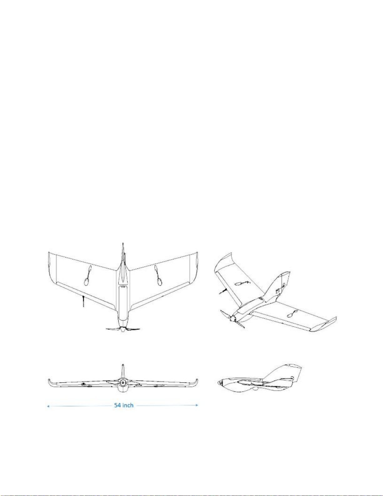
This Pilot’s Operating Handbook is for the PHX fixed wing unmanned
aircraft system (UAS).
The PHX UAS is a nominally 4 pound (2 kg), hand launched, electric
powered, autopilot controlled aircraft that is remotely operated using a
tablet or laptop computer with a digital wireless data-link. The PHX UAS
can be fitted with a number of sensor payloads for precision agriculture,
survey and mapping, and public safety applications.
3-VIEW DRAWING

1-2
Copyright Sentera LLC 2018
ACRONYMS, ABBREVIATIONS, SYMBOLS, AND
TERMINOLOGY
UAS TERMS:
UAS –unmanned aircraft system
GCS –ground control station
UA –unmanned aircraft
UAV –unmanned aerial vehicle
AIRCRAFT TERMS:
Pitot tube –Device that measures the speed of the air passing
by/over the air vehicle.
Control Surfaces (Elevons) –Flaps on the trailing edge of wings that
control aircraft orientation.
Fuselage –Primary enclosure that houses the autopilot, sensor, and
other essential electronics.
Payload/Sensor –Camera unit installed into the UAV to capture
mission imagery.
Servos –Geared electronic motors that operate control surfaces via
commands from the autopilot.
Magnetometers –Electronic sensors that measure the magnetic
orientation of aircraft (e.g. N,S,E,W).
C.G. –center of gravity
AVIATION TERMS:
Winds aloft –Speed and direction of winds at flight altitude.
Ground speed –Speed of the aircraft over the ground.
Airspeed –Speed of the relative wind over the aircraft and
conversely, the speed of the aircraft relative to the air mass.
GPS Altitude –Altitude of an aircraft determined by readings from the
GPS unit.

1-3
Copyright Sentera LLC 2018
Barometric Altitude –(a.k.a. Baro Altitude) Altitude of aircraft
determined by readings from the barometric altimeter.
MSL –Altitude of an aircraft as measured above the average sea
level, calculated as a weighted average from the baro and GPS
measurements.
Pitch, Roll, and Yaw (Aircraft Attitude) –Pitch: nose up or down, Roll:
banking of wings, Yaw: left or right lateral motion of the aircraft nose.
USER INTERFACE TERMS:
Takeoff waypoint –Waypoint that aircraft will fly to after takeoff.
Land Waypoint –Waypoint that aircraft will touch down at when
landing.
Survey Waypoint Pattern –Waypoint pattern that outlines image
capture area and dictates where photos are taken.
Loiter Waypoint –Waypoint in which aircraft will circle indefinitely at a
predetermined altitude.
Artificial Horizon –Shows aircraft yaw, pitch, roll, and telemetry.
Failsafes –Time and altitude limits that an aircraft will adhere to in
case of lost link, lost GPS, and low battery.

2-1
Copyright Sentera LLC 2018
SECTION 2: LIMITATIONS
The operator must ensure the system is operated within limits. The
autopilot and ground control station software have some built-in checks that
aid the operator, but ultimately the operator is responsible for keeping the
system within all limits.
SPEED LIMITS
The autopilot in the PHX UAS automatically maintains airspeed based on
the Pitot-static pressure measurements:
Vstall: 22 mph (19 kts, 10 m/s), standard sea level conditions
Vmin: 30 mph (26 kts, 13 m/s), autopilot limited
Vcruise: 35 mph (30 kts, 16 m/s), autopilot default
Vmax: 45 mph (40 kts, 20 m/s)
ALTITUDE LIMITS
The PHX UAS autopilot automatically maintains commanded altitude based
on the onboard barometric and GPS altitude sensors:
Minimum recommended cruise altitude: 150 ft. (46 m) AGL
Maximum density altitude: 14,000 ft. (4300 m) MSL (mean sea level)
Maximum altitude above ground: flight operations must remain
below the maximum altitude allowed by local regulations or local
airspace authority. Often this means below 400 ft. (120 m) AGL
(height above ground).

2-2
Copyright Sentera LLC 2018
WIND LIMITS
Maximum winds aloft = 28 mph (24 kts, 12 m/s)
Maximum crosswind takeoff = 5 mph (4 kts, 2 m/s) crosswind
component
Maximum crosswind landing = 15 mph (13 kts, 7 m/s) crosswind
component
PRECIPITATION AND MOISTURE LIMITS
Do not fly in precipitation, fog, mist, or clouds.
GPS LIMITS
Minimum 10 GPS satellite fix recommended.
TEMPERATURE LIMITS
Operational temperature limits
Minimum = 14 F (-10 C)
Maximum = 120 F (50 C)
Storage temperature limits
Minimum = -10 F (-23 C)
Maximum = 120 F (50 C)
BATTERY LEVEL LIMITS
Maximum voltage: 12.6 volts
Nominal voltage: 11.1 volts
Minimum voltage: 9.0 volts
Warning: battery will be damaged if discharged below 9.0 volts during
operation or if left in storage for a long time. Check battery level every 3
months when storing and recharge to 50% storage level as needed.
Tip: Never go below 10% battery level during flight. Never go below 6%
battery level during ground handling.

2-3
Copyright Sentera LLC 2018
TAKE-OFF AND LANDING AREA LIMITS
The launch and recovery area must be free of obstructions within an area
measuring 50 meters wide and 100 meters long, as shown below. This
area should also be kept free of persons during launch and landing, other
than the operator that is doing the launching.

3-1
Copyright Sentera LLC 2018
SECTION 3: EMERGENCY PROCEDURES
The following are emergency procedures for the operator and autonomous
failsafe behaviors of the UAV.
LOSS OF PROPULSION
If propulsion power is lost the aircraft will automatically continue to fly the
pre-planned waypoints while gliding to the ground.
•Maintain visual contact with the aircraft.
•Avoid obstacles along the path using the normal waypoint and flight
mode commands to change the aircraft’s gliding direction (e.g. GoTo
location).
GCS SOFTWARE CRASH OR LOCK-UP
If the GCS software crashes or locks up:
•Force the software application to close.
•Re-launch the GCS software.
•Reconnect to the UAV in the normal way.
If the UAV does not receive communication from the GCS software within
the Lost Link time out period, the automatic Lost Link procedure will begin.
LOST LINK
If lost link occurs attempt troubleshoot and re-establish communications
with the aircraft:
•Maintain visual contact with the aircraft.
•Check antenna placement for RF line-of-sight.
•Check that the ground radio is powered
•Check cable or wireless connections between CommsBox and
computer.

3-2
Copyright Sentera LLC 2018
Aircraft autonomous behavior during lost link
If communications are not re-established within the time out period
(typically 30 seconds) the aircraft will automatically Return to Land
(RTL).
If communications are regained, the operator may command the
aircraft back onto the flight plan or proceed to land the aircraft.
LOST GPS
If the aircraft loses GPS the operator should:
•Maintain visual contact with the aircraft.
Aircraft autonomous behavior during lost GPS:
If the aircraft loses GPS lock and it is not regained within a short
period the autopilot will cease flying the pre-programmed waypoints
and will begin slowly descending in a spiral circle pattern while it
waits to regain GPS lock or lands on the ground.
OTHER
For other emergencies the operator may:
•immediately press RTL to return to the landing location.
•put the aircraft in “Pause”or “Hold” mode and click “GoTo” locations
on the map to move the aircraft around.
•command the aircraft to glide to the ground at any time (if in
communications with the aircraft) by disarming the motor and
confirming “Emergency Stop” command.
MEDICAL
If there is a medical emergency with any involved personnel, flight
operations should cease and emergency responders should be contacted.

3-3
Copyright Sentera LLC 2018
REPORTING
Incident reports should be logged and applicable authorities notified as
required.
Any incidents pertaining to the performance of the aircraft or other parts of
the system should be reported to the manufacturer. Telemetry logs files
from the Ground station, payload, and aircraft may be required to send to
the manufacturer.

4-1
Copyright Sentera LLC 2018
SECTION 4: NORMAL PROCEDURES
FLIGHT PLANNING IN SENTERA GROUND CONTROL
SOFTWARE
Sentera Ground Control is the software used to plan missions and control
the aircraft.
The data links should automatically connect once both the aircraft and GCS
are powered, the laptop is connected to the comms box (via cable or
wirelessly), and the software is running.
To create a flight plan in Sentera Ground Control:
1. Click on the Plan view icon.
2. Remove the existing mission from the aircraft by pressing File and
the Clear Vehicle Mission buttons.

4-2
Copyright Sentera LLC 2018
3. Create a Takeoff waypoint: Place the first waypoint by clicking on
the Waypoint icon and clicking a location on the map. By default the
first waypoint becomes your “Takeoff” waypoint which is where the
aircraft will fly to after launch.

4-3
Copyright Sentera LLC 2018
4. Adjust the altitude of the Takeoff waypoint in the mission list on the
right hand side using the boxes to the right or left of the highlighted
box (Warning: do not adjust the Pitch value, leave at the default
which should be 15 degrees).
5. Place additional waypoints as needed.

4-4
Copyright Sentera LLC 2018
6. Create a Survey Pattern: to map an area with the camera payload
click on Pattern and then Survey to create the default Survey pattern.
Adjust the settings in the Survey edit box on the right.

4-5
Copyright Sentera LLC 2018
Click and drag corner dots, click the + dots, and drag the center dot to
adjust the size and shape of the survey.
Tip: If possible try to plan the survey perpendicular to the wind direction
with the aircraft starting downwind and working its way upwind. This
method may allow you to reduce the turnaround distance and optimize
flight performance.

4-6
Copyright Sentera LLC 2018
7. Plan a Landing Pattern: Click Pattern and then Fixed Wing Landing.
Click a location on the map for the landing point. Adjust the landing
direction by dragging the Loiter point. Adjust other landing values in the
Landing Pattern edit box on the right.
Tip: PHX recommended landing approach distance is 1300 ft. To
shorten this approach you will need to reduce the loiter altitude in the
Landing Pattern edit box.
Other manuals for PHX
5
Table of contents
Other Sentera Toy manuals


Popular Toy manuals by other brands

Faller
Faller Newspaper stand, waffle baker instructions

Freewing
Freewing F/A-18E Super Hornet FJ1071 user manual

Seagull Models
Seagull Models Magic Star 3D EP Assembly manual

Radio Flyer
Radio Flyer 986Z instruction manual

Fisher-Price
Fisher-Price K7188 manual

PREZIOSI
PREZIOSI KOKUYO Flair Klixi Mixi manual

MGA Entertainment
MGA Entertainment Smoshins SURprise Maker Kit quick start guide

POLA G
POLA G 331739 quick start guide

Eduard
Eduard MLRS NATO exterior quick start guide

J-Power
J-Power Explorer Prop Assembly and operating manual

Little Tikes
Little Tikes You Drive Excavator Assembly instructions

AquaCraft
AquaCraft mini Alligator Tours manual


