Sentera RSMFX-3 User manual
RSMFX-3 MULTIFUNCTIONAL CO2
ROOM TRANSMITTER
Mounting and operating instructions

www.sentera.eu
MIW-RSMFX-3-EN-000-11/10/2023 2 - 7
back to the table of contents
RSMFX-3 MULTIFUNCTIONAL CO2ROOM
TRANSMITTER
Table of contents
SAFETY AND PRECAUTIONS 3
PRODUCT DESCRIPTION 4
ARTICLE CODE 4
INTENDED AREA OF USE 4
TECHNICAL DATA 4
STANDARDS 4
OPERATIONAL DIAGRAMS 5
WIRING AND CONNECTIONS 6
MOUNTING & OPERATING INSTRUCTIONS IN STEPS 6
OPERATING INSTRUCTIONS 8
VERIFICATION OF INSTALLATION 9
TRANSPORT AND STORAGE 9
WARRANTY AND RESTRICTIONS 10
MAINTENANCE 10

www.sentera.eu
MIW-RSMFX-3-EN-000-11/10/2023 3 - 7
back to the table of contents
RSMFX-3 MULTIFUNCTIONAL CO2ROOM
TRANSMITTER
SAFETY AND PRECAUTIONS
Read all the information, the datasheet, Modbus Register map, mounting and
operating instructions and study the wiring and connection diagram before working
with the product. For personal and equipment safety, and for optimum product
performance, make sure you entirely understand the contents before installing, using
or maintaining this product.
Forsafetyandlicensing(CE)reasons,unauthorisedconversionand/ormodifications
of the product are inadmissible.
e product should not be exposed to abnormal conditions, such as extreme
temperatures, direct sunlight or vibrations. Long-term exposure to chemical
vapours in high concentration can affect the product performance. Make sure the
work environment is as dry as possible; avoid condensation.
All installations shall comply with local health and safety regulations and local
electrical standards and approved codes. is product can only be installed by an
engineer or a technician who has expert knowledge of the product and the safety
precautions.
Avoid contact with energised electrical parts. Always disconnect the power supply
before connecting, servicing or repairing the product.
Always verify that you apply appropriate power supply to the product and use
appropriate wire size and characteristics. Make sure that all the screws and nuts
are well tightened and fuses (if any) are fitted well.
Recyclingofequipmentandpackagingshouldbetakenintoconsiderationandthese
shouldbedisposedofinaccordancewithlocalandnational legislation/regulations.
In case there are any questions that are not answered, please contact your
technical support or consult a professional.

www.sentera.eu
MIW-RSMFX-3-EN-000-11/10/2023 4 - 7
back to the table of contents
RSMFX-3 MULTIFUNCTIONAL CO2ROOM
TRANSMITTER
PRODUCT DESCRIPTION
e RSMFX-3 series are multifunctional room transmitters which measure
temperature, relative humidity, CO2concentration levels and ambient light. ey
feature a wide range of low voltage power supply and three analogue / modulating
outputs for temperature, relative humidity and CO2. All parameters are accessible
via Modbus RTU.
ARTICLE CODE
Article code Supply Imax Connection type
RSMFG-2R 24 VDC 80mA Terminal block24 VAC ±10% 120 mA
RSMFF-2R 24 VDC 80 mA
INTENDED AREA OF USE
■Monitoring temperature, relative humidity and CO2levels in HVAC applications
■Suitable for residential and commercial buildings
■For indoor use only
TECHNICAL DATA
■3 analogue / modulating outputs:
►0—10 VDCmode: min. load 50 kΩ (RL≥ 50 kΩ)
►0—20 mA: max. load 500 Ω (RL≤ 500 Ω)
►PWM (open-collectortype): PWM Frequency: 1 kHz,min. load 50 kΩ (RL≥50 kΩ);
PWM voltage level 3,3 VDC or 12 VDC
■CO2sensor stabilising time: 35 seconds
■Ambient light sensor with adjustable ‘active’ and ‘standby’ level
■3 LEDs for status indication with adjustable light intensity
■Accuracy: ±0,4 °C (5—50 °C); ±3 % rH (20—80 % rH); ±50 ppm CO2 ± 2,5 % of
reading (400—2.000 ppm CO2); ±50 ppm CO2 ± 3 % of reading (1.001—2.000 ppm
CO2); ±50 ppm CO2 ±5 % of reading(2.001—5.000 ppm CO2)
■Enclosure:
►rear plate: plastic ABS, black (RAL 9004)
►front cover: ASA, ivory (RAL 9010)
■Protection standard: IP30 (according to EN 60529)
■Typical range of use:
►temperature: 0—50 °C
►rel. humidity: 0—95 % rH, (non-condensing)
►CO2: 400—2.000 ppm
■Storage temperature: -10—60 °C
STANDARDS
■EMC directive 2014/30/EU:
►EN 60730-1:2011 Automatic electrical controls for household and similar
use - Part 1: General requirements
►EN 61000-6-1:2007 Electromagnetic compatibility (EMC) - Part 6-1: Generic
standards-Immunityforresidential,commercialandlightindustrialenvironments
►EN 61000-6-3:2007 Electromagnetic compatibility (EMC) - Part 6-3: Generic
standards - Emission standard for residential, commercial and light-industrial
environments Amendments A1:2011 and AC:2012 to EN 61000-6-3
►EN 61326-1:2013 Electrical equipment for measurement, control and laboratory
use - EMC requirements - Part 1: General requirements
►EN 61326-2-3:2013 Electrical equipment for measurement, control and
www.sentera.eu
MIW-RSMFX-3-EN-000-11/10/2023 5 - 7
back to the table of contents
RSMFX-3 MULTIFUNCTIONAL CO2ROOM
TRANSMITTER
laboratory use - EMC requirements - Part 2-3: Particular requirements Test
configuration, operational conditions and performance criteria
■Low Voltage Directive 2014/35/EU
►EN 60529:1991 Degrees of protection provided by enclosures (IP Code)
Amendment AC:1993 to EN 60529
►EN 60730-1:2011 Automatic electrical controls for household and similar use -
Part 1: General requirements
■WEEE 2012/19/EC
■RoHs Directive 2011/65/EC
►EN IEC 63000:2018 Technical documentation for the assessment of electrical
and electronic products with respect to the restriction of hazardous substances
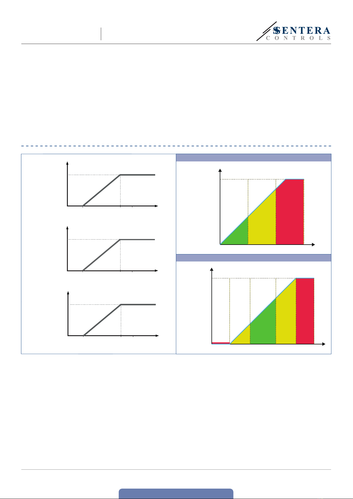
OPERATIONAL DIAGRAMS
Analogue /
modulating output
1 [%]
100
0 Min
range
Max
range
50 T [°C]
Analogue /
modulating output
2 [%]
100
0Min
range
Max
range
100 rH [%]
Analogue /
modulating output
3 [%]
100
0Min
range
Max
range
5.000 CO2 [ppm]
LED indication of CO2sensor (default setting)
10
0
20
30
40
50
60
70
80
90
100
Alert 1
level
Alert 2
level
Analogue /
modulating
output [%]
CO2 [ppm]
LED indication of temperature and humidity sensor
10
0
20
30
40
50
60
70
80
90
100
Minimum
range
Minimum
alert
Maximum
alert
Analogue /
modulating
outputs [%]
T [°C] / rH [%]
Maximum
range
Out of range
Out of range
Alert range
Alert range
Within range
www.sentera.eu
MIW-RSMFX-3-EN-000-11/10/2023 6 - 7
back to the table of contents
RSMFX-3 MULTIFUNCTIONAL CO2ROOM
TRANSMITTER
WIRING AND CONNECTIONS
Article type RSMFF-3 RSMFG-3
VIN 18—34 VDC 18—34 VDC 15—24 VAC ±10%
GND Ground Common ground AC ~
AModbus RTU (RS485), signal A Modbus RTU (RS485), signal A
/B Modbus RTU (RS485), signal /B Modbus RTU (RS485), signal /B
AO1 Analogue / modulating output 1 for temperature
measurement (0—10 VDC / 0—20 mA / PWM) Analogue / modulating output 1 for temperature
measurement (0—10 VDC / 0—20 mA / PWM)
GND Ground AO1 Common ground
AO2 Analogue / modulating output 2 for relative humidity
measurement (0—10 VDC / 0—20 mA / PWM) Analogue / modulating output 2 for relative humidity
measurement (0—10 VDC / 0—20 mA / PWM)
GND Ground AO2 Common ground
AO3 Analogue / modulating output 3 for CO2
measurement (0—10 VDC / 0—20 mA / PWM) Analogue / modulating output 3 for CO2
measurement (0—10 VDC / 0—20 mA / PWM)
GND Ground AO3 Common ground
Connections Spring contact terminal blocks, cable cross section: 1,5 mm2
ATTENTION e -F version of the product is not suited for 3-wire connection. It has separate
grounds for power supply and analogue output. Connecting both grounds together
might result in incorrect measurements. Minimum 4 wires are required to connect
-F type sensors.
e -G version is intended for 3-wire connection and features a ‘common ground’.
is means that the ground of the analogue output is internally connected with
the ground of the power supply. For this reason, -G and -F types cannot be
used together on the same network. Never connect the common ground of -G
type articles to other devices powered by a DC voltage. Doing so might cause
permanent damage to the connected devices.
MOUNTING & OPERATING INSTRUCTIONS IN STEPS
Before you start mounting the unit, read carefully “Safety and Precautions”.
Choose a smooth surface for installation (a wall, panel, etc.).
ATTENTION Mount the sensor in a well-ventilated area where it receives adequate airflow
for proper operation and hide it from direct sunlight. Make sure it can be easily
accessed for service.
Follow these steps:
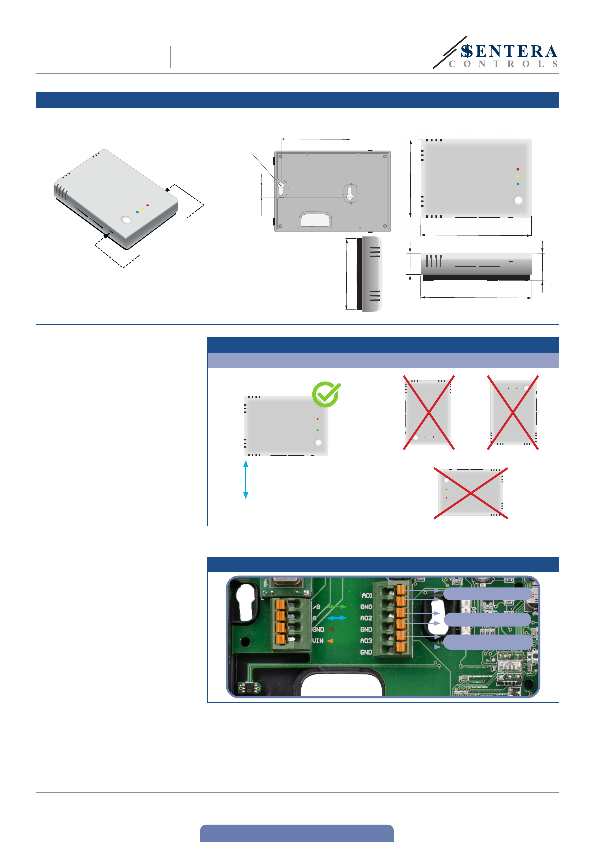
1. Using a flat screwdriver, remove the front white cover by releasing the snap-fits
on both sides (see Fig. 1 Snap-fits release).
2. Insert the cables through the opening on the rear plate (see Fig. 2 Mounting
dimensions.)
3. Using suitable fastening materials (not supplied), position the room sensor
at least 1,5 m from the floor. Mind the correct mounting position and unit
dimensions. See Fig. 2 and Fig. 3.
www.sentera.eu
MIW-RSMFX-3-EN-000-11/10/2023 7 - 7
back to the table of contents
RSMFX-3 MULTIFUNCTIONAL CO2ROOM
TRANSMITTER
Fig. 1 Snap-fits release Fig. 2 Mounting dimensions
Push here to
release
2x Ø 6
59,8
9,8
74,5
104,5
20
104,5
25,6
70,5
Fig. 3 Mounting position
Correct Incorrect
Position at min. 1,5 m
from the floor
4. Do the wiring according to the wiring diagram (see Fig.4).
Fig. 4 Wiring
Analogue output 1 - T
Analogue output 2 - rH
Analogue output 3 - CO2
5. Put back the cover and snap it in.
6. Switch on the mains supply.
7. Customise the factory settings to the desired ones via the 3SModbus software
or SenteraWeb. For the default factory setting see the Modbus register map of
the product.
www.sentera.eu
MIW-RSMFX-3-EN-000-11/10/2023 8 - 10
back to the table of contents
RSMFX-3 MULTIFUNCTIONAL CO2ROOM
TRANSMITTER
Optional settings
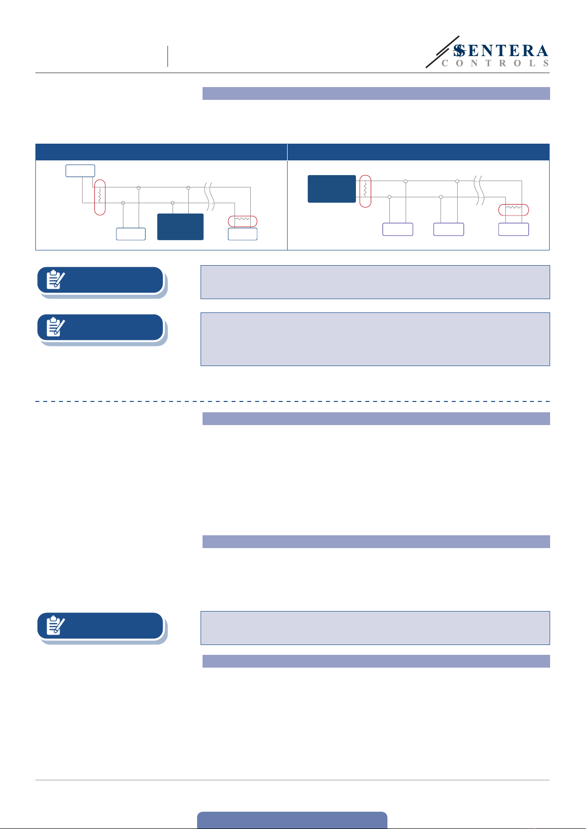
To assure correct communication, the NBT needs to be activated in only two devices
on the Modbus RTU network. If necessary, enable the NBT resistor via 3SModbus or
Sensistant (Holding register 9).
Example 1 Example 2
RX
ТX
NBT
NBT
Slave 2
Master
Slave n
Slave 1
Slave 2
Slave 1
RX
ТX
NBT
NBT
Master
Slave n
NOTE On a Modbus RTU network, two bus terminators (NBTs) need to be activated.
NOTE For the complete Modbus register data, see the Modbus Register Map of the
product. is is a separate document linked to the article code on the website
containing the list of registers. Products with earlier firmware versions may not be
compatible with this list.
OPERATING INSTRUCTIONS
Calibration procedure:
No relative humidity and temperature calibration is necessary.
Sensor calibration is not necessary. All sensor elements are calibrated and tested in
our factory.
e CO2sensor element is self-calibrating to compensate sensor drift. By default,
the ABC logic self-calibrating algorithm is enabled. is algorithm is designed to
be used in applications where CO2concentrations will drop to outside ambient
conditions (400 ppm) at least once a week, typically during unoccupied periods. It is
advisable to disable the self-calibrating algorithm in situations where the CO2level
will not drop to 400 ppm within the mentioned period.
Firmware update
New functionalities and bug fixes are made available via a firmware update. In
case your device does not have the latest firmware installed, it can be updated.
SenteraWeb is the easiest way to update the firmware of the unit. In case you do not
have an internet gateway available, the firmware can be updated via the 3SM boot
application (part of the Sentera 3SMcenter software suite).
NOTE Make sure the power supply does not get interrupted during the “bootload”
procedure, otherwise you risk losing unsaved data.
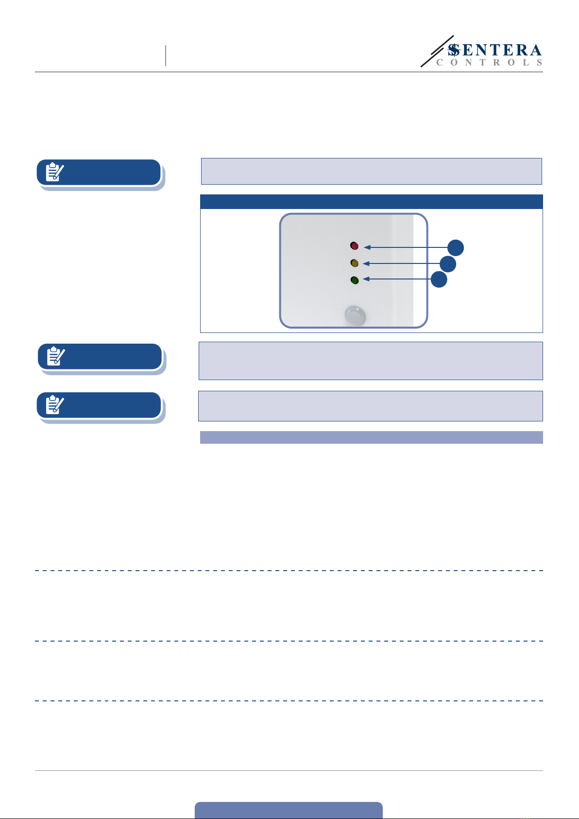
LED indications
1. When the green LED is on, measured temperature or relative humidity value is
within the alert range’s minimum and maximum values or the CO2level is below
Alert 1 level. (Fig. 5 - 1).
2. When the yellow LED is on, the measured temperature or relative humidity value
is in the alert range or the CO2value is higher than or equal to Alert 1 level.
e yellow LED blinks when Modbus communication is terminated and Holding
register 8 is activated (Modbus timeout > 0 seconds) (Fig. 5 - 2).
e LED stops blinking once the Modbus communication has been restored.
For Modbus safety timeout, alert yellow LED indication takes precedence over
www.sentera.eu
MIW-RSMFX-3-EN-000-11/10/2023 9 - 10
back to the table of contents
RSMFX-3 MULTIFUNCTIONAL CO2ROOM
TRANSMITTER
blinking yellow LED.
3. When the red LED is on, the measured temperature or relative humidity value is
below or equal to the minimum measurement range value or above or equal to
the maximum value or when the measured CO2level is higher than or equal to
Alert 2 level (Fig. 5 - 3).
Blinking red LED indicates loss of communication with a sensor (Fig. 5 - 3).
NOTE When the sensor is in bootloader mode, the green and yellow LEDs flash
alternately. During the firmware download, the red LED is flashing additionally.
Fig. 5 LED indications
3
2
1
NOTE By default, the LED indication refers to CO2measurements. is can be changed
to temperature or relative humidity values via Modbus Holding Register 79 (see
Table Holding registers).
NOTE e intensity of the LEDs can be adjusted between 0 and 100 % with a step of 10
% according to the value set in Holding register 80.
Ambient light sensor
e measured light intensity in lux is available in Input Register 41. Additionally,
an active and standby level can be defined in Holding registers 35 and 36. If the
measured value is below the standby level, above the active level, or somewhere in
between, Input Register 42 will indicate that:
■Ambient light level < standby level: Input Register 42 indicates “Standby”.
■Ambient light level > active level: Input Register 42 indicates “Active”.
■Standby level < Ambient light level < Active level: Input Register 42 indicates “Low
intensity”.
VERIFICATION OF INSTALLATION
One of the LEDs lights up after the power is turned on, depending on the status of
the variable being measured. Check the connections if this is not the case.
TRANSPORT AND STORAGE
Avoid shocks and extreme conditions; stock in original packing.
WARRANTY AND RESTRICTIONS

www.sentera.eu
MIW-RSMFX-3-EN-000-11/10/2023 10 - 10
back to the table of contents
RSMFX-3 MULTIFUNCTIONAL CO2ROOM
TRANSMITTER
e warranty against manufacturing flaws is valid for two years starting from
the date of delivery. Any alterations or adjustments to the product absolve the
manufacturer of all liability. e manufacturer disclaims all liability for typographical
or other errors in this document.
MAINTENANCE
In normal conditions this product is maintenance-free. If soiled, clean with a dry or
damp cloth. In case of heavy pollution, clean with a non-aggressive product. In these
circumstances the unit should be disconnected from the supply. Pay attention that
no fluids enter the unit. Only reconnect it to the supply when it is completelydry.
Table of contents
Other Sentera Transmitter manuals


