Ebtron GTC116 User manual

EBTRON • 1663 Hwy. 701 S., Loris SC 29569 • Toll Free: 800.2EBTRON (232.8766) • Fax: 843.756.1838 • Internet: EBTRON.com
Model GTC116
Installation Guide
Gold Series Thermal Dispersion Airflow Measurement Technology
Advantage III
Gold Series by Ebtron
Installation Guide
GTC116
“Plug & Play” Transmitter with
Combination RS-485 Network Output and Dual Analog Output
Document Name: IG_GTC116_R3B
a measurable difference!
EBTRON
BACnet is a registered trademark of ASHRAE. ASHRAE does not endorse, approve or
test products for compliance with ASHRAE standards. Compliance of listed products to
the requirements of ASHRAE Standard 135 is the responsibility of BACnet International
(BI). BTL is a registered trademark of BI.
ModelsGTC116andGTM116
PartNumber930‐0220
LISTED
EuropeanUnion
Shipments

2 EBTRON • 1663 Hwy. 701 S., Loris SC 29569 • Toll Free: 800.2EBTRON (232.8766) • Fax: 843.756.1838 • Internet: EBTRON.com
GOLD SERIES GTC116 TRANSMITTER
a measurable difference!
EBTRON
IG_GTC116_R3A
TableofContents
1GTC116TRANSMITTERINSTALLATION......................................................................................................................4
1.1GTC116MechanicalDimensions.........................................................................................................................4
2GTC116TRANSMITTERINTERIORVIEW/FEATURES...................................................................................................5
3GTC116TRANSMITTERPOWERANDPROBECONNECTIONS.....................................................................................6
3.1PowerTransformerSelection.............................................................................................................................6
3.2ConnectingPowertotheTransmitter................................................................................................................6
3.3ConnectingSensorProbestotheTransmitter....................................................................................................7
4GTC116ANALOGOUTPUTANDNETWORKCONNECTIONS.......................................................................................8
4.1GTC116‐ANALOGOUTPUTWIRING...................................................................................................................8
4.2GTC116‐RS‐485NETWORKWIRINGCONNECTIONS.........................................................................................9
4.2.1GTC116‐RS‐485NetworkCableSpecifications..........................................................................................9
4.2.2GTC116‐ConnectingtoanRS‐485Network:..............................................................................................9
4.2.3GTC116‐SettingTransmitterTerminationforRS‐485Network.................................................................9
4.3GTC116‐TransmitterSetupforRS‐485NetworkOperation..............................................................................9
4.3.1GTC116‐RS‐485NetworkOptionsandCommunications
MenuSettings..................................................9
4.3.2GTC116‐SettingRS‐485NetworkProtocol...............................................................................................10
4.3.3GTC116‐SettingTransmitterAddress.......................................................................................................10
4.3.4GTC116‐SettingBaudRate.......................................................................................................................10
4.3.5GTC116‐SettingModbusParity..................................................................................................................10
4.3.6GTC116‐SettingBACnetDeviceInstanceNumber.....................................................................................10
4.3.7GTC116‐ResettingCommunications
OptionstoFactoryDefaultValues..................................................10
5GTC116TRANSMITTERSTART‐UP,INITIALIZATIONANDSETUPMENUS.................................................................12
5.1ChangingtheSystemofUnits‐IPorSIUnits...................................................................................................12
5.2GTC116TransmitterCalibration.......................................................................................................................12
5.3GTC116LCDDisplayNotifications.....................................................................................................................12
5.4FactoryDefaultMenuSettingsforGP1SensorProbes.....................................................................................13
5.5GTC116ChangingFactoryDefaultSetupMenuSettings..................................................................................14
5.5.1SetupMenuOptions..................................................................................................................................14
5.5.2AdjustingtheLowLimitCutoffFeature.....................................................................................................14
5.5.3SelectingActualandStandardOutputMeasurementType......................................................................14
5.5.4OutputScaling...........................................................................................................................................14
5.5.5ChangingtheLCDDisplayfromVolumetricFlowCFMtoVelocityFPM....................................................14
5.5.6ConvertingtheAnalogOutputSignalfromFPMtoCFM...........................................................................14
5.5.7LockingtheConfigurationSettings............................................................................................................14
5.6GTC116‐AlarmFeatures..................................................................................................................................15
5.6.1AverageAlarm(AO2ASGN=ALRM)............................................................................................................15
5.6.2TroubleAlarm(AO2ASGN=TRBL)..............................................................................................................15
5.6.3NoFault(NOFAULT=HI)............................................................................................................................15
5.6.4AlarmIndications.......................................................................................................................................15
5.6.5LowAlarm‐“LOALRM=ON”.....................................................................................................................15
5.6.6HighAlarm‐“HIALRM=ON”.....................................................................................................................15
5.6.7TroubleAlarm‐“AO2ASGN=TRBL”...........................................................................................................15
5.7GTC116‐AnalogOutputTypeSelectionandSetup.........................................................................................16
5.7.1GTC116‐ConvertingAnalogOutputSignalValuestoAirflowandTemperature......................................16
5.7.2GTC116‐AO1/AO2OUTPUTTEST‐SendingaTestOutputSignaltotheHostControlSystem..............16
5.8ViewingSensorData.........................................................................................................................................17
5.8.1ViewingSensorDataontheLocalLCDDisplay..........................................................................................17
5.8.2ViewingSensorDataviaBACnet,ModbusnetworksorviaEB‐LinkReader.............................................17
5.8.3SensorAddressingandProbePositioning..................................................................................................17
6SETUPMENUS..........................................................................................................................................................17
7WIRINGDIAGRAM....................................................................................................................................................17
APPENDIXA‐ADVANTAGE3‐SETUPMENUS............................................................................................................18
APPENDIXB‐GTC116WIRINGDIAGRAM...................................................................................................................18

EBTRON • 1663 Hwy. 701 S., Loris SC 29569 • Toll Free: 800.2EBTRON (232.8766) • Fax: 843.756.1838 • Internet: EBTRON.com 3
GOLD SERIES GTC116 TRANSMITTER
a measurable difference!
EBTRON
IG_GTC116_R3A
ListofFigures
Figure1.GTC116MechanicalDimensions....................................................................................................................4
Figure2.GTC116TransmitterInteriorView/Features..................................................................................................5
Figure3.ConnectingPowertotheTransmitter............................................................................................................6
Figure4.TypeAandTypeBTransmitterConnectorPanelDetail.................................................................................7
Figure5.ConnectorDetail.............................................................................................................................................7
Figure6.GTC116CombinationAnalog/RS‐485TransmitterInteriorDetail..................................................................8
Figure7.SensorAddressingandProbePositioningDetail..........................................................................................17
ListofTables
Table1.GTC116PowerTransformerSelectionGuide..................................................................................................6
Table2.GTC116BACnetObjectsList..........................................................................................................................11
Table3.GTC116ModbusRegisterMap......................................................................................................................11
Table4.Standard“IP”and“SI”MenuUnitsAbbreviations........................................................................................12
Table5.FactoryDefaultMenuSettings......................................................................................................................13
Table6.GTC116AlarmTypesandNotifications.........................................................................................................15
Table7.GTC116ConvertingAnalogOutputValuestoAirflow/Temperature.............................................................16
4 EBTRON • 1663 Hwy. 701 S., Loris SC 29569 • Toll Free: 800.2EBTRON (232.8766) • Fax: 843.756.1838 • Internet: EBTRON.com
GOLD SERIES GTC116 TRANSMITTER
a measurable difference!
EBTRON
IG_GTC116_R3A
1GTC116TRANSMITTERINSTALLATION
TheGTC116transmitterisdesignedforuseinanenvironmentbetween‐20°Fto120°F(‐28.8°Cto48.8°C)where
itwillnotbeexposedtorainorsnow.Installtransmitteruprightandinafieldaccessiblelocation.Theenclosure
accepts1/2in.(12.7mm)electricalfittingsforsignalandpowerwiringatbothsidesatthetopoftheenclosure.
Locatethetransmittersothattheconnectingcablesfromallofthesensorprobeswillreachthereceptaclesonthe
bottomofthetransmitterenclosure.
Inlocationsexposedtodirectrainand/orsnow,thetransmittermustbeenclosedinaNEMA4
enclosure.
Leaveunobstructedspaceofatleast9in.(228.6mm)above,2in.(50.8mm)toeachsideand3.5
in.(88.9mm)belowthetransmittertoallowforcoverremoval,sensorconnectionsandheat
dissipation.
Locatethetransmitterinalocationthatcanbereachedbyallconnectingcablesfromthesensor
probes.
Donotdrillintothetransmitterenclosuresincemetalshavingscoulddamagetheelectronics.
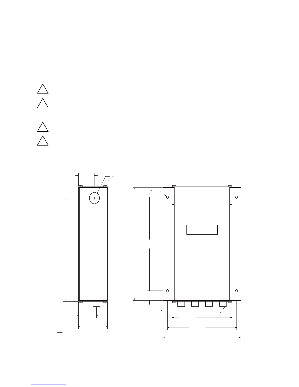
1.1 GTC116MechanicalDimensions
Figure1.GTC116MechanicalDimensions
!
!
!
!
2) IF UNIT HAS 2 PROBE CONNECTIONS THEN IT IS A TYPE "A" UNIT.
IF UNIT HAS 4 PROBE CONNECTIONS THEN IT IS A TYPE "B" UNIT.
NOTES:
1) MEASUREMENTS IN BRACKETS ARE IN MILLIMETERS.
Ø.88
[Ø22.23 mm]
6.69
[169.86 mm]
5.94
[150.81 mm]
1.38
[34.93 mm]
SEE NOTE 2
1.56
[39.67 mm]
Ø.19
[Ø4.76 mm]
2.50
[63.50 mm]
7.94
[201.55 mm]
.38
[9.53 mm]
7.19
[182.55 mm]
8.69
[220.73 mm]
.75
[19.05 mm]
5.19
[131.76 mm]
PROVIDE 3.5 INCH MINIMUM CLEARANCE AT
BOTTOM FOR CONNECTOR ACCESS.
PROVIDE 9 INCH MINIMUM CLEARANCE AT TOP
FOR COVER ACCESS (SLIDE UP TO REMOVE).
PROVIDE 2 INCH MINIMUM CLEARANCE AT BOTH
SIDES OF ENCLOSURE
1.38
[35.05 mm]
[O4.83 mm]
O.19
[182.63 mm]
[201.68 mm]
[9.65 mm]
[39.62 mm] [131.83 mm]
[150.88 mm]
[169.93 mm]
[O22.35 mm]
O.88
EBTRON • 1663 Hwy. 701 S., Loris SC 29569 • Toll Free: 800.2EBTRON (232.8766) • Fax: 843.756.1838 • Internet: EBTRON.com 5
GOLD SERIES GTC116 TRANSMITTER
a measurable difference!
EBTRON
IG_GTC116_R3A
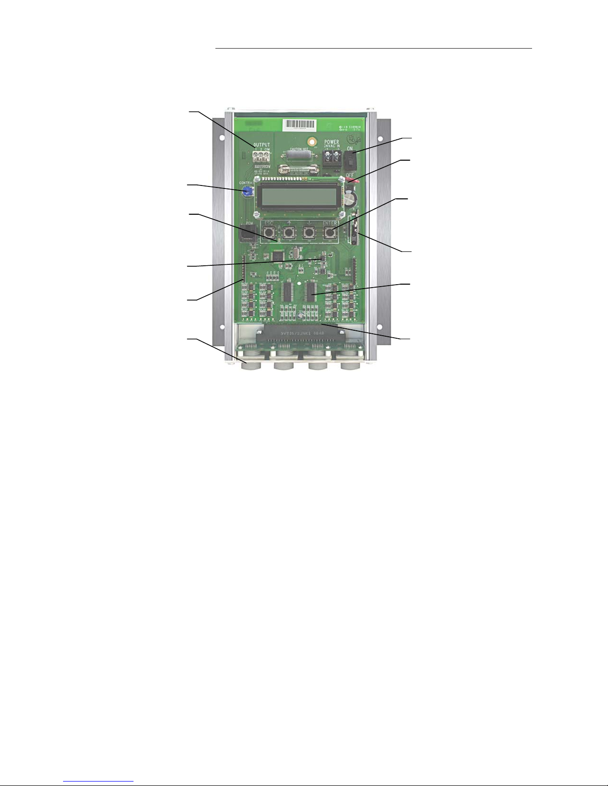
2GTC116TRANSMITTERINTERIORVIEW/FEATURES
Figure2.GTC116TransmitterInteriorView/Features
Outputsignalterminals
(Note:Theoutputfunction
isdependentonwhich
networkcardisinstalled)
LCDcontrast
TransmitterstatusLED
(Green1secondflashnormal;
2secondflashforfault)
Highaccuracy
A/Dconverter
Goldplatedinterconnects
tooptionaloutputcards
Positivelockingcable
receptacleswithgold
interconnects
Powerswitch
Switchingpowersupply
conservesenergyand
reducesheat
Pushbuttoninterface
simplifiesfieldconfiguration
(Note:devicesareplugandplayand
generallydonotrequireconfiguration.)
Expansionport
Multiplexersindependently
measuresensorvoltages
from1upto16sensingpoints
Goldplatedinterconnectsto
sensorinputreceptacles

6 EBTRON • 1663 Hwy. 701 S., Loris SC 29569 • Toll Free: 800.2EBTRON (232.8766) • Fax: 843.756.1838 • Internet: EBTRON.com
GOLD SERIES GTC116 TRANSMITTER
a measurable difference!
EBTRON
IG_GTC116_R3A
3GTC116TRANSMITTERPOWERANDPROBECONNECTIONS
3.1 PowerTransformerSelection
Selecta24VACtransformerbasedonthemaximumpowerrequirementsindicatedonthetransmitterlabel(20
VA)orfromthetablebelow.Theoperatingsupplyvoltage(transmitterpower“ON”withallsensorprobes
connected)shouldnotbelessthan22.8VACorgreaterthan26.4VAC.
Total
Sensors
Minimum
VAReq.
Total
Sensors
Minimum
VAReq.
Total
Sensors
Minimum
VAReq.
Total
Sensors
Minimum
VAReq.
112514 917 1319
213615 10 17 1419
313715 11 18 1520
414816 12 18 1620
3.2 ConnectingPowertotheTransmitter
Connect24VACpowertothelarge,twopositionpowerinputterminallabeled“POWER”ontheupperrighthand
sideofthemaincircuitboard(Figure3).Sincetheoutputsignalsareisolatedfromthepowersupply,itisnot
necessarytoprovideanisolated(secondarynotgrounded)powersource.
MultipleGTC116transmitterswiredtoasingletransformermustbewired“in‐phase”(L1toL1,
L2toL2).
Table1.GTC116PowerTransformerSelectionGuide
Figure3.ConnectingPowertotheTransmitter
!
PowerFuse
ReplacewithUL®listed,1.5amp,fastactingonly
P.N.800‐1115(10pack)
24VACInputPower
22.8to26.4VAC
20VAmax.
L2
L1
Power
Switch
REPLACE WITH
1.5 AMP
FAST ACTING ONLY
OUTPUT
1 2 COM
POWER
24VAC IN
L2 L1
ON
OFF
EBTRON • 1663 Hwy. 701 S., Loris SC 29569 • Toll Free: 800.2EBTRON (232.8766) • Fax: 843.756.1838 • Internet: EBTRON.com 7
GOLD SERIES GTC116 TRANSMITTER
a measurable difference!
EBTRON
IG_GTC116_R3A
SQUEEZE
SQUEEZE
RECEPTACLE
LOCKING TABS
LOCKED INTO
UNDERCUT IN
RECEPTACLE
SQUEEZE
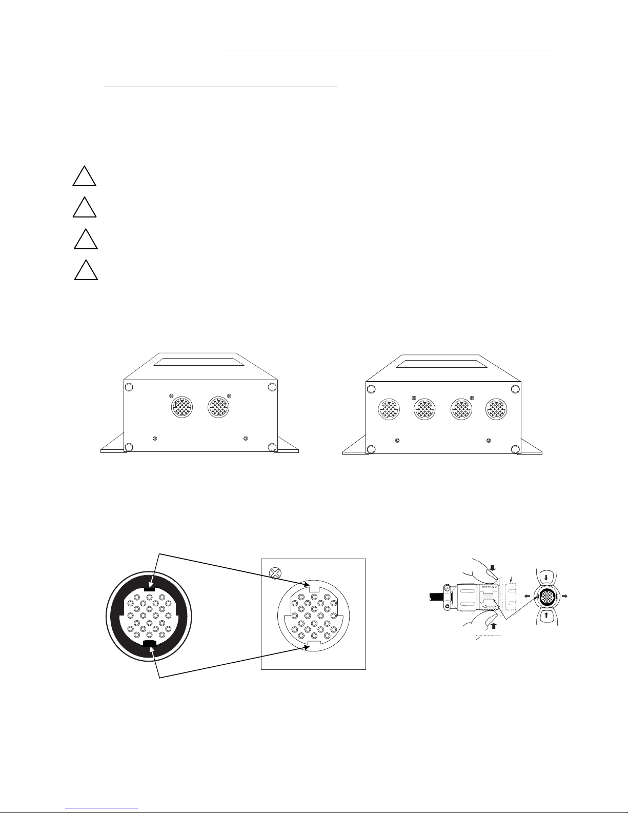
3.3 ConnectingSensorProbestotheTransmitter
Afterinstallingthesensorprobesandtransmitter,connecteachofthesensorprobecableplugstothecircular
receptacleslocatedatthebottomoftheGTC116transmitterenclosure.Probesare“PlugandPlay”anddonot
havetobeconnectedtoaspecificreceptacleonthetransmitterunlesstraversedataisdesired(seenotebelow).
TransmittersacceptonlyGP1andGB1sensors.
Providea“driploop”atthetransmitteriftherewillbethepotentialforwaterrunoffor
condensationalongthesensorprobecable(s).
Sensorprobecableplugsare“keyed”asshownbelow.Lineupplugwithreceptacleandpush
straightontoreceptacle.
DONOTTWIST.Squeezecableplug“ribs”towardsreceptaclewhenremoving.Forcingthecable
pluginoroutofthereceptaclewilldamagetheconnectorsandvoidwarranty.
Whentraversedataisdesired(especiallywhenusingtheEB‐LinkReader),probesshouldbe
installedandconnectedtothetransmitterusingthemountingconventionspecifiedinthe
separateGP1/GB1sensorprobeInstallationGuide.Properinstallationsimplifiessensorlocation
decodingduringdataanalysis.
Figure4.TypeAandTypeBTransmitterConnectorPanelDetail
Figure 5.ConnectorDetail
TypeBTRANSMITTER
Accepts1to4probesupto4sensorseach
Squeezeandthenpulltoremove
DONOTTWIST!
TypeATRANSMITTER
Accepts1or2probesupto8sensorseach
!
!
!
!
8 EBTRON • 1663 Hwy. 701 S., Loris SC 29569 • Toll Free: 800.2EBTRON (232.8766) • Fax: 843.756.1838 • Internet: EBTRON.com
GOLD SERIES GTC116 TRANSMITTER
a measurable difference!
EBTRON
IG_GTC116_R3A
4GTC116ANALOGOUTPUTANDNETWORKCONNECTIONS
ThissectioncontainsanalogandnetworkoutputwiringinstructionsfortheGTC116transmitterwithRS‐485and
DualAnalogoutputs.
4.1 GTC116‐ANALOGOUTPUTWIRING
AnalogoutputconnectionsaremadeatthetopleftofthetransmittermaincircuitboardOUTPUTconnectoras
showninFigure6.IndependentlinearanalogoutputsareprovidedforairflowatOUTPUTterminal1,andfor
temperature(oralarm)atOUTPUTterminal2,eachwithovervoltageandovercurrentprotection.Airflowand
temperatureoutputsarefieldselectableforeither0‐5/0‐10VDCor4‐20mA.TheOUTPUTterminal2canbe
assignedasanAlarmoutputtoprovideanactivehigh,activelowortroublealarmoutput.Outputsaregalvanically
isolatedfromthemainpowersupplytopermitsimpleintegrationwithvirtuallyallbuildingautomationsystems.
Whenconfiguredfor4‐20mAoutput,theGTC116isa“4‐wire”device.Thehostcontrolsshallnotprovide
anyexcitationvoltagetotheoutputoftheGTC116.
Fortheanalogoutputs,shieldedcableisrecommended.Towiretheanalogoutputs,slidethecoverplateupand
offoftheenclosure.Ensurethatthepowerswitchisinthe“OFF”position.Connectsignalwiresforairflowrate
andtemperature(oralarm)tothesmall,threepositionoutputterminallabeled“OUTPUT”ontheupperlefthand
sideofthemaincircuitboardasshowninFigure6.
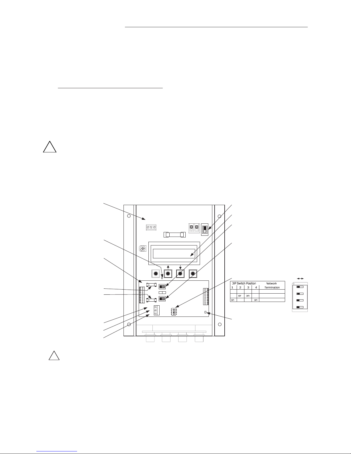
Figure6.GTC116CombinationAnalog/RS‐485TransmitterInteriorDetail
ON
OFF
OFF ON
ESC ENTER
CONTRAST
REPLACE WITH
1.5 AMP
FAST ACTING ONLY
OUTPUT
1 2 COM
POWER
24VAC IN
L2 L1 ON
OFF
RS-485
NET COM
NET -
NET +
ON
TERM
F1
F2
VDC mA
OUT 1
OUT 2
RS-485
ANALOG OUTPUT
1: Airflow
2: Temperature/Alarm
COM: Common
(RS-485 output below)
Transmitter Status LED
(Green 1 second flash normal;
2 second flash for trouble)
Combination Analog/
RS-485 Output Card
P.N. 800-1825
Analog Output Fuses
F1=OUT1
F2=OUT2
UL Listed 0.125 Amp
P.N. 800-1105 (Qty:10)
NET COM*
NET -
.
NET +
RS-485
OUTPUT
(For Analog Output, see
separate output above)
Power Switch
LCD Display
SW1 (for OUT1)
Airflow Output Signal Select
SW2 (for OUT2)
Temp./Alarm/Trouble Output
Signal Select
VDC: 0-5/0-10VDC or
mA: 4-20 mA
RS-485 Activity LED
(Green LED indicating RS-485 network activity)
*CAUTION
The common for the ANALOG and the RS-485 outputs must be at the same potential.
For ISOLATED RS-485 output, COM connection MUST BE CONNECTED to network common.
For NON-ISOLATED output, COM connection MUST BE CONNECTED to the common ground that other network devices are using (typically the
ground side of the 24VAC supply - L2 of the POWER terminals). Refer to RS-485 Network Wiring Connections paragraph for additional detail.
off off off off No Termination
off off End of Line
off off Fail-safe Bias
!
!
SW3 TERMINATION Switch

EBTRON • 1663 Hwy. 701 S., Loris SC 29569 • Toll Free: 800.2EBTRON (232.8766) • Fax: 843.756.1838 • Internet: EBTRON.com 9
GOLD SERIES GTC116 TRANSMITTER
a measurable difference!
EBTRON
IG_GTC116_R3A
4.2 GTC116‐RS‐485NETWORKWIRINGCONNECTIONS
4.2.1 GTC116‐RS‐485NetworkCableSpecifications
TheRS‐485networkcableshallbeshieldedtwistedpairwithacharacteristicimpedanceof100to130ohms.
Distributedcapacitancebetweenconductorsshallbelessthan100pFpermeter.Distributedcapacitancebetween
conductorsandshieldshallbelessthan200pFpermeter.Themaximumrecommendedlengthofanetwork
segmentis1200meterswithAWG18cable.
4.2.2 GTC116‐ConnectingtoanRS‐485Network:
ConnecttheNET+,NET‐andCOMterminalswithshieldedtwistedpaircablemeetingthespecificationsdefinedin
thepreviousparagraph(typicallyusingtwopairs;onepairfor+/‐and(atleastoneof)thewiresinotherpairfor
COMwhenusing2‐paircable).Theconnectiontothenetworkmustbemadeina"daisychain”configuration."T"
connectionsandstubsareNOTpermitted.Theshieldshouldbeterminatedatoneendonthenetworkonly.
*CAUTION
ForISOLATEDoutput,theCOMconnectionMUSTBECONNECTEDtothenetworkcommonforproper
operation.Inaddition,whentheAnalogOutputisconcurrentlyusedwiththeRS‐485Output,theCommon
connectionforbothAnalogandRS‐485Outputsmustbeatthesamepotential.
ForNON‐ISOLATEDoutput,theCOMconnectionMUSTBECONNECTEDtothecommongroundthatisused
bytheothernetworkdevices(typicallythegroundsideofthe24VACsupply;terminalL2atthePOWER
connectorblockinFigure6).Inaddition,whentheAnalogOutputisconcurrentlyusedwiththeRS‐485
Output,theCommonconnectionforbothAnalogandRS‐485Outputsmustbeatthesamepotential.
4.2.3 GTC116‐SettingTransmitterTerminationforRS‐485Network
The GTC116 is shipped with the Termination switch set for No termination, which is the recommended setting
for devices installed on the network bus anywhere EXCEPT at the ends of the bus/segment. EBTRON
recommends the following termination strategy for devices connected at the ends of the network
bus/segment:
When the transmitter is at one end of the network, it should be terminated with “End of Line” (or 120 ohm
standard) termination, and the device at the other end should be terminated with “Fail Safe Bias”
termination. This method provides proper network termination and ensures that the bus is in a known state
during idle-line conditions (when no devices are driving the bus). EBTRON GTC116 transmitters include
three termination options for “End of Line” (standard 120 ohm) and “Fail-safe Bias” (recommended at one
end of the bus) or for “No Termination”. Termination is selected by setting TERMINATION DIP switch SW3 as
shown below.
Check the network/network segment to ensure that only one device is terminated with either method. If multiple devices
are terminated as described above, network segment operation will be adversely affected.
4.3 GTC116‐TransmitterSetupforRS‐485NetworkOperation
For RS-485 operation, network connections are made on the GTC116 Combination board as shown in Figure
6, and set up is as follows. Network protocol, MS/TP address, device instance number and baud rate options
are all selected with- in the NETWORK section of SETUP menu shown in Appendix A.
NOTE:
Prior to power up, network configuration and termination switches must be set as shown in Figure 6.
Wiring to the RS-485 network is accomplished after setting the GTC116 network configuration switches.
4.3.1 GTC116‐RS‐485NetworkOptionsandCommunications
MenuSettings
The transmitter is shipped from the factory with the protocol set for BACnet MS/TP Master, address 2, MS/TP
Device ID 2, Baud rate of 76,800 and no termination. Initial RS-485 communications settings are
accomplished within the GTC116 NETWORK sub menu shown in Appendix A. Termination is set up by the
TERM DIP switch SW3 located on the Combination card shown in Figure 6.
!
!
!

10 EBTRON • 1663 Hwy. 701 S., Loris SC 29569 • Toll Free: 800.2EBTRON (232.8766) • Fax: 843.756.1838 • Internet: EBTRON.com
GOLD SERIES GTC116 TRANSMITTER
a measurable difference!
EBTRON
IG_GTC116_R3A
4.3.2 GTC116‐SettingRS‐485NetworkProtocol
Transmitter protocol can be set for MS/TP or MODBUS as shown in the NETWORK submenu (Appendix A).
Tables 2 and 3 list the specific features of each protocol.
4.3.3 GTC116‐SettingTransmitterAddress
The GTC116 is factory set to an address of 2. Each transmitter must be assigned a unique address between 0
and 127 for BACnet or 1 and 247 for Modbus prior to connecting it to the network. Set the address in the
NETWORK submenu (Appendix A).
4.3.4 GTC116‐SettingBaudRate
The GTC116 transmitter default baud rate for MS/TP is 76,800 and for MODBUS is 19,200. Baud rate can be
configured in the NETWORK sub menu (Appendix A).
4.3.5 GTC116‐SettingModbusParity
When using Modbus communications protocol, Parity can be changed in the NETWORK submenu. Parity can
be set for Even (default), Odd, None 1 (with 1 stop bit), or None 2 (with 2 stop bits).
4.3.6 GTC116‐SettingBACnetDeviceInstanceNumber
When using BACnet communications protocol, the factory default Device Instance Number is 2. Device
Instance Number can be set as shown in the NETWORK submenu. Device Instance Number can also be
changed to any number between 0 and 4,194,302 by writing to the Device Object's Object Identifier Property
over the network.
4.3.7 GTC116‐ResettingCommunications
OptionstoFactoryDefaultValues
Communications options can be reset to factory default values (asterisk) * values using the GTC116 RESET
NET menu option.

EBTRON • 1663 Hwy. 701 S., Loris SC 29569 • Toll Free: 800.2EBTRON (232.8766) • Fax: 843.756.1838 • Internet: EBTRON.com 11
GOLD SERIES GTC116 TRANSMITTER
a measurable difference!
EBTRON
IG_GTC116_R3A
Function
Address
Type
Units Description
Range/Value
2
10001
boolean
Trouble
Status
0:OK,
1:Trbl
4
30001-30002
float FPM
Avera
g
e
Airflow
0to
15,000
4
30003-30004
float °F
Avera
g
e
Tem
p
erature
-20 to
160
4
30005
word
Numbe
r
o
f
Inserts
0to
16
4
30006
word
0
4
30007
word
Alarm
Status
0: No
alarm
1: High
Alarm
2: Low
Alarm
3:
Both
4
30008
word
Connecto
r
C1
Sensors
0 to
8
4
30009
word
Connecto
r
C2
Sensors
0 to
8
4
30010
word
Connecto
r
C3
Sensors
0 to
8
4
30011
word
Connecto
r
C4
Sensors
0 to
8
4
30012-30043
float
FPM
Airflow
Flow
Traverse
0 to
15,000
30012-30013
Insert 1
Flow
↕↕
30042-30043
Insert 16
Flow
4
30044-30075
float
°F
Tem
p
erature Traverse
-20 to
160
30044-30045
Insert 1
Tem
p
↕↕
30074-30075
Insert 16
Tem
p
4
30076-30077
float
Sq.Ft. Area
0 to
100
4
300202
word
Float word
order
0: high word
first;
1: low word
first
Analog Values
AV, 1 Area sq.ft.
AV, 2 Traverse Data Status 0=None, 1=Flow,
2=Temp, 3=Both
AV, 3 Flow Traverse FPM
↕↕↕
AV, 18 Flow Traverse FPM
AV, 19 Temperature Traverse °F
↕↕↕
AV, 34 Temperature Traverse °F
Notes:
1. Flow and Temp traverse must be enabled through AV2.
2. User Executed Services Supported:
Subscribe COV, Read Property, Write Property,
Device Communication Control, Who-Is.
Analog Inputs
Type, ID Name Default
Units
Device GTC116
AI, 1 Average Flow CFM
AI, 2 Average Temperature °F
AI, 3 Alarm Status 0: No alarm,
1: High Alarm,
2: Low Alarm,
3: Both
Table2. GTC116BACnetObjectsList
Table3. GTC116ModbusRegisterMap
BACnetMS/TP

12 EBTRON • 1663 Hwy. 701 S., Loris SC 29569 • Toll Free: 800.2EBTRON (232.8766) • Fax: 843.756.1838 • Internet: EBTRON.com
GOLD SERIES GTC116 TRANSMITTER
a measurable difference!
EBTRON
IG_GTC116_R3A
5GTC116TRANSMITTERSTART‐UP,INITIALIZATIONANDSETUPMENUS
Toensureasuccessfulstart‐up,verifythattheairflowmeasuringstationsensorprobesandtransmitterare
installedinaccordancewithEBTRONguidelines.
Checkthephysicalinstallation,powerconnectionsandmodelspecificsignalwiringpriortoturningthe
powerswitchtothe“ON”position.
Movethepowerswitchtothe“ON”position.Thetransmitterexecutesacompleteself‐checkeachtimethepower
isturnedonthattakes10secondstocomplete.
5.1 ChangingtheSystemofUnits‐IPorSIUnits
TheGTC116transmitterisprovidedwiththesystemofunitssettoIP.TochangetoSIunits,simultaneouslypress
andreleasethe“ENT”and“ESC”buttonsduringnormaloperation.“IP/SIUNITS”willbeindicatedontheLCD
display.RefertoAppendixASYSTEMOFUNITSMENUfordetailsontheSystemofUnitsmenu.NotethatSetup
MenuitemsareshowninIPSystemOfUnits.WhenSISystemofUnitsisselected,theunitsofmeasure
abbreviationsusedinthemenusisshowninTable4.
“IP”SystemofUnitsDescription“SI”SystemofUnits Description
FPMFeetperminuteMPS Meterspersecond
CFMCubicfeetperminuteLPS Literspersecond
SQFSquarefeetSQM Squaremeters
FFahrenheit CCelsius
5.2 GTC116TransmitterCalibration
TheGTC116useshighqualityindustrialgradecomponentsandisdesignedforyearsoftrouble‐freeoperation.
Periodicrecalibrationofthetransmitterisneitherrequiredorrecommended.Transmitterfieldcalibrationverifiers
areavailableforpurchasefromEBTRONforinstallationsrequiringperiodicvalidationofinstrumentation.Contact
EBTRONformoreinformation.
5.3 GTC116LCDDisplayNotifications
Followingabriefinitializationatpowerup,theLCDdisplayautomaticallydisplaysairflowandtemperaturewith
unitsofmeasurementinalluppercase(caps)characters.Thedisplayprovidesadditionalinformationonsystem
statusandalarmconditions.RefertotheALARMFEATURESsectionofthismanualforadditionaldetailonAlarm
andTroubleErrorcodeindications.
Table4.Standard“IP”and“SI”MenuUnitsAbbreviations
!

EBTRON • 1663 Hwy. 701 S., Loris SC 29569 • Toll Free: 800.2EBTRON (232.8766) • Fax: 843.756.1838 • Internet: EBTRON.com 13
GOLD SERIES GTC116 TRANSMITTER
a measurable difference!
EBTRON
IG_GTC116_R3A
5.4 FactoryDefaultMenuSettingsforGP1SensorProbes
TheGTC116transmitteris“plugandplay”anddoesnotrequiresetupunlessanetworkoptionisselectedthat
requiresconfiguration.Table5showsthefactorydefaultsettingsforallcompatiblesensorprobes.
TochangetheFactoryDefaultSettings,see:CHANGINGFACTORYDEFAULTSETUPMENUSETTINGS.
Display Description I-P S.I.
AIRFLOW= Airflow measurement method, Actual or Standard. ACT ACT
*LCDU/M= Airflow units of measure ACFM LPS
*AREA= Free area where station is located (required for volumetric measurement) 0.00 sq.ft.
(see note)
0.000 sq.meters
(see note)
*AO1 SGNL= Output 1 signal type voltage or mA (airflow) mA mA
*AO1 UM= Output 1 units of measure AFPM MPS
*AO1 FS= Output 1 signal full scale 5,000 FPM 25 MPS
*LLIMIT= Low limit cutoff 0 AFPM 0 MPS
*FLOW ADJ= Output 1 Offset-Gain On/Off Off Off
*GAIN= Output 1 Gain factor 1.000 1.000
*OFF= Output 1 Offset factor 0.000 0.000
*TEMP METH= Temperature Averaging Weighted Avg. Weighted Avg.
*AO2 SGNL= Output 2 signal voltage or mA (temperature or alarm) mA (see alarms) mA (see alarms)
*AO2 MS= Output 2 signal minimum scale -20º F -30º C
*AO2 FS= Output 2 signal full scale 160º F 70º C
*LCD INTG= Number of flow calculations to be averaged for LCD display. 100 100
*AO1 INTG= Number of flow calculations to be averaged for AO1 output. 30 30
*EB-LK INT= Number of flow calculations to be averaged for EB-Link readings. 300 300
*ALT= Altitude for flow correction relative to mean sea level (0 ft). 0 ft 0 m
*AO2 ASGN = *AO2 ASGN = TEMP Output 2 Assigned Type is Temperature TEMP TEMP
*SETPNT= Alarm setpoint value. For AO2 ASGN=ALARM , operates in conjunction
with TOL=value.
0 0
*TOL= Alarm range tolerance value. For AO2 ASGN=ALARM , this setting
establishes the alarm range relative to the SETPNT= value.
10% 10%
*NO FAULT= Sets the AO2 normal (not alarm) output state relative to the full scale
analog output selected. HI provides maximum full scale under normal
conditions and minimum scale during alarm. LO provides minimum full
scale under normal conditions and maximum scale during alarm.
HI HI
*DELAY= Time that the alarm condition must exist before alarm output is activated. 2 minutes 2 minutes
*ZERO OFF = Set to YES to inhibit LO alarm condition when flow reading is below
LLIMIT= setting. Set to NO to disable this feature.
NO NO
*RESET = Set to AUTO to have alarm self-clear when alarm condition no longer
exists. Set to MANUAL to require manual reset of alarm.
AUTO AUTO
Note: For GP1 probes, area is stored in one-wire, but can be changed.
Table5. FactoryDefaultMenuSettings

14 EBTRON • 1663 Hwy. 701 S., Loris SC 29569 • Toll Free: 800.2EBTRON (232.8766) • Fax: 843.756.1838 • Internet: EBTRON.com
GOLD SERIES GTC116 TRANSMITTER
a measurable difference!
EBTRON
IG_GTC116_R3A
5.5 GTC116ChangingFactoryDefaultSetupMenuSettings
5.5.1 SetupMenuOptions
TheGTC116Transmitterissetupandtestedatthefactorytobefullyoperationalwhensensorprobesare
connectedandpowerisapplied(setthepowerswitchtothe“ON”position).Factorysettingscaneasilybe
changedusingtheSETUPMENUbysimultaneouslypressingandreleasingthe“UP”and“DOWN”buttonswhilethe
transmitterisinitsnormaloperatingmode.AppendixAdetailstheSETUPmenus.NavigatethroughtheSETUP
menustomakechangestothetransmitterconfiguration.Thesettingstakeeffectimmediately.Thefollowingare
commonfieldmodificationstothefactorydefaultsettings.
5.5.2 AdjustingtheLowLimitCutoffFeature
Thelowlimitcutofffeature(menuitemLLIMIT=)forcestheoutputsignalfortheairflowratetozerowheneverthe
calculatedairflowratefallsbelowthespecifiedLowLimitvalue.
5.5.3 SelectingActualandStandardOutputMeasurementType
Thetransmitterissetfromthefactorytoprovideactualairflowmeasurementunits(displayedas“ACFM”and
“AFPM”).Inthismode,airflowmeasurementsarecalculatedforactualinletconditions.Ifusingactualairflow,
correctionsforaltitudeareenteredthroughtheALT=settingintheSetupmenu.Ifdesired,theoutputcanbeset
toprovidestandardairflowmeasurementunits(displayedas“SCFM”and“SFPM)whichprovidesmeasurements
thatarecorrectedtostandardconditions.
5.5.4 OutputScaling
EBTRON’sGoldSeriessensorsareindividuallycalibratedbetween0andthefactorydefaultfullscaleinwind
tunnelstraceabletotheNationalInstituteofStandardsandTechnology(NIST).Sensorsareindependentand
produce“percentofreading”accuracy.Changingthefullscalevaluedoesnotchangetheaccuracyofthedevice.
FactorydefaultanalogoutputscalingcanbechangedwithintheSETUPmenus.
5.5.5 ChangingtheLCDDisplayfromVolumetricFlowCFMtoVelocityFPM
TheGTC116transmitterisshippedfromthefactorytoindicatevolumetricflow.TodisplayvelocityinFPM,enter
theSETUPmenuandintheDISPLAYsubmenu,changethe“*LCDUM=ACFM”to“*LCDUM=AFPM”.Changingthe
LCDdisplayunitswillnotaffecttheanalogoutputsignal.
5.5.6 ConvertingtheAnalogOutputSignalfromFPMtoCFM
TheGTC116transmitterisshippedfromthefactorywithanalogoutput“OUTPUT1”settoindicatevelocityin
AFPM.Toautomaticallyconvertthisanalogvelocityoutputtovolumetricflow(ACFM),simplysetthe*AO1UM
fromAFPM(default)toACFMintheSETUPmenu.Ifyouwishtomanuallyconvertthevelocityoutputto
volumetricflow(ACFM),simplymultiplytheindicatedoutputvelocity(inFPM)bythefreeareaoftheairflow
probeinstallationlocation.ReferalsotoTable7foracompletelistingofconversionsforeachoftheanalog
outputsoftheGTC116.TheAO1fullscaleanalogoutput(OUTPUT1)valueisdeterminedbytheAO1FSsetting
withintheSETUPmenu.
5.5.7 LockingtheConfigurationSettings
TheGTC116transmitterconfigurationsettingscanbelockedatoneofthreesecuritylevelswithintheSECURITY
submenuusingtheLOCKSEC=item.
WhenLOWsecuritylevelisselected(LOCKSEC=LOW)thelast4digitsoftheboardserialnumberareautomatically
assignedasthelockcode.Toseeboardserialnumber,navigatetoDIAGNOSTICSmenuinSERIALNUMBERSitem.
WhentheMEDsecuritylevelisselected(LOCKSEC=MED)theuserentersandconfirmsasecuritycode.Inthe
eventthatthiscodeislost/misplaced,EBTRONcanprovideakeythatisuniquetothetransmittertounlockit.
ContactEBTRONcustomerserviceforthiscode.
WhentheHIGHsecuritylevelisselected(LOCKSEC=HIGH)theuserentersandconfirmsasecuritycode.Inthe
eventthatthiscodeislost/misplaced,thetransmittermustbereturnedtothefactoryinordertounlockit.
WhenLOCKSEC=HIGHisselected,theuserdefinedsettingcanonlybechangedafterenteringtheuser
definedcode.STORETHELOCKCODEINASAFELOCATION!Forsecurityreasons,theHIGHlevellockcode
canonlyberesetbyreturningthetransmittertothefactory.
!

EBTRON • 1663 Hwy. 701 S., Loris SC 29569 • Toll Free: 800.2EBTRON (232.8766) • Fax: 843.756.1838 • Internet: EBTRON.com 15
GOLD SERIES GTC116 TRANSMITTER
a measurable difference!
EBTRON
IG_GTC116_R3A
5.6 GTC116‐AlarmFeatures
AnalogoutputAO2(OUT2)canbeassignedtofunctionasanalarmoutput.TheAO2alarmoutputcanbe
assignedintheSETUPmenutooperateasanaveragealarm(A02ASGN=ALRM)orasatroublealarm(AO2
ASGN=TRBL)formonitoringthestatusofthetransmitterandsensors.TheAO2ASGN=settingislocatedinthe
ANALOGOUTsubmenuoftheSETUPmenu.ThetransmitterLCDdisplaywillindicatetheAlarmstatusfor2
seconds,andwillcyclethroughanyotheralarmsifmultiplealarmeventsareactivefor2secondseach,andthen
displaythecurrentactualflowfor2seconds.DetailedsetupoftheAlarmfeaturesisshownintheSetupmenu.
5.6.1 AverageAlarm(AO2ASGN=ALRM)
AO2outputisassignedasanaverageairflowalarmoutput.Usefulforapplicationswherealowflowalarmora
highflowalarmforoperationoutsideofadefinedrange(setpointandtolerance)isrequired.
5.6.2 TroubleAlarm(AO2ASGN=TRBL)
AO2outputisassignedasatransmittertroublealarmindicatingafaultwithinthetransmitterorasensorofthe
airflowmeasurementsystem.ThetransmitterLCDwillindicateatroublecodeandabriefdescriptionofthe
trouble.ContactEBTRONcustomerserviceforadditionalinformationorassistancewithtroublecodes.
5.6.3 NoFault(NOFAULT=HI)
WhenAO2outputisassignedasanalarm,thissettingconfiguresthenormaloutputconditiontobeHIorLO
relativetothefullscaleanalogoutputlevelselectedwhennofaultconditionexists.
5.6.4 AlarmIndications
Table6detailsthealarmtypes,LCDindicationsandAO2alarmoutputindication.Usercanselecteitherorbothof
thetwoAverageAlarmsortheTroubleAlarm.
5.6.5 LowAlarm‐“LOALRM=ON”
TheLowAlarmisactivatedwhentheaverageairflowfallstoadefinedlevelbelowtheSETPNT=value.Thedefined
levelisequaltotheSETPNT=valueminusthecalculatedvalueof(TOL=value*SETPNT=value).Onceactive,thealarm
canbeclearedwhentheaverageairflowrisesabovethesetpointminuscalculatedtolerancevalue.
5.6.6 HighAlarm‐“HIALRM=ON”
TheHighAlarmisactivatedwhentheaverageairflowrisesaboveadefinedlevelabovetheSETPNT=value.The
definedlevelisequaltotheSETPNT=valueplusthecalculatedvalueof(TOL=value*SETPNT=value).Onceactive,
thealarmcanbeclearedwhentheaverageairflowfallsbelowthesetpoint+calculatedtolerancevalue.
5.6.7 TroubleAlarm‐“AO2ASGN=TRBL”
TheTroublealarmprovidestroublecodesusefulforisolatingsetupissuesorproblemswithinthetransmitteror
sensors.ThetransmitterLCDwillindicateTROUBLE!regardlessofwhetherAO2isassignedtoTRBLE.The
Diagnosticsubmenucanbeengagedfortheerrorcodeandabriefdescriptionofthetrouble.ContactEBTRON
customerserviceforinformationontroubleshootingusingtheTroubleerrorcodes.
Table6.GTC116AlarmTypesandNotifications
ALARM OUTPUT
ASSIGNMENT TYPE
LOCAL LCD DISPLAY OF ALARM
TYPE AND NOTIFICATION
ANALOG OUTPUT 2
ALARM INDICATION
NETWORK
ALARM INDICATION
**LOW ALARM**
(Average Alarm)
Display alternates between **LOW
ALARM** (then any other alarms) and
actual reading for 2 seconds each.
**HIGH ALARM**
(Average Alarm)
Display alternates between **HIGH
ALARM** (then any other alarms) and
actual reading for 2 seconds each.
TROUBLE !
(Trouble Alarm)
Display indicates TROUBLE !
(Refer to DIAGNOSTIC menu to obtain a
brief description of the error and any
other alarms).
On alarm or trouble, OUT2 is
active high (or active low)
relative to the full scale
maximum (or minimum)
analog value as determined
by the SETUP Menu “NO
FAULT=” selection. Individual
sensor velocities can be
viewed using the Diagnostics
submenu.
Alarm Status is available at
BACnet Objects and
Modbus Registers. Refer to
BACnet Objects List and
Modbus Register Map for
additional detail.

16 EBTRON • 1663 Hwy. 701 S., Loris SC 29569 • Toll Free: 800.2EBTRON (232.8766) • Fax: 843.756.1838 • Internet: EBTRON.com
GOLD SERIES GTC116 TRANSMITTER
a measurable difference!
EBTRON
IG_GTC116_R3A
5.7 GTC116‐AnalogOutputTypeSelectionandSetup
TheanalogoutputsignaltypeatAO1(OUT1,airflow)andAO2(OUT2,temperature/alarm)canbesetformAor
VDCoutputbysettingswitchesSW1/SW2(Figures6and7)andbyselectingthe4‐20mA,0‐5VDCor0‐10VDC
rangesintheANALOGOUTsubmenuoptions*AO1RNGE=/*AO2RNGE=settings.Thetransmitterisshipped
fromthefactorywithSW1/SW2andSetupmenuoptions*AO1RNGE=and*AO2RNGE=setfor4‐20mA.
5.7.1 GTC116‐ConvertingAnalogOutputSignalValuestoAirflowandTemperature
Table7listsspecificconversionequationsforanalogvoltageorcurrentoutputoptions.
5.7.2 GTC116‐AO1/AO2OUTPUTTEST‐SendingaTestOutputSignaltotheHostControl
System
Atestoutputsignalbetween0and100%ofthefullscaleoutput(4‐20mAor0‐5VDC/0‐10VDC)canbeprovided
bytheGTC116transmittertoverifyproperconversionoftheoutputsignalsfromthetransmitteratthehost
controlsystem.Tosetafixedoutputsignalforairflowandtemperature,navigatetotheOUTPUTTESTsubmenuin
theTOOLSmenu.OUT1andOUT2testsareindependentlyaccessed,andtheoutputwillmaintainthe%selected
untilthe“ESC”buttonispressedandnormaloperationresumes.
Table7.GTC116ConvertingAnalogOutputValuestoAirflow/Temperature
TO CONVERT TO
Airflow (FPM, MPS) Output Voltage/10 x FS1 Output Voltage/5 x FS1 (Output Current-4)/16 x FS1
Airflow (CFM) Area (SQF) x Output/10 x FS1 Area (SQF) x Output/5 x FS1 Area (SQF) x (Output - 4)/16 x FS1
Airflow (LPS) Area (SQM) x Output/10 x FS1 x 1000 Area (SQM) x Output/5 x FS1 x 1000 Area (SQM) x (Output - 4)/16 x FS1 x 1000
TO CONVERT TO
Airflow (CFM, LPS) Output Voltage/10 x FS1 Output Voltage/5 x FS1 (Output Current - 4)/16 x FS1
TO CONVERT TO
Temp (°F,°C) Output Voltage/10 x (FS2-MS2) +MS2 Output Voltage/5 x (FS2-MS2) +MS2 (Output Current - 4)/16 x (FS2-MS2) +MS2
NOTES:
FS1 is AO1 full scale analog output value from ANALOG OUT MENU.
FS2 is AO2 full scale analog output value from ANALOG OUT MENU.
MS2 is AO2 minimum scale analog output value from ANALOG OUT MENU.
0-10 VDC 0-5 VDC 4-20 mA
ANALOG OUTPUT SCALING AND TYPE
0-10 VDC 0-5 VDC 4-20 mA
When OUTPUT 2 is Configured as Temperature (°F,°C):
ANALOG OUTPUT SCALING AND TYPE
0-10 VDC 0-5 VDC 4-20 mA
ANALOG OUTPUT SCALING AND TYPE
When OUTPUT 1 is Configured as Linear Airflow (FPM, MPS):
When OUTPUT 1 is Configured as Volumetric Airflow (CFM, LPS):

EBTRON • 1663 Hwy. 701 S., Loris SC 29569 • Toll Free: 800.2EBTRON (232.8766) • Fax: 843.756.1838 • Internet: EBTRON.com 17
GOLD SERIES GTC116 TRANSMITTER
a measurable difference!
EBTRON
IG_GTC116_R3A
5.8 ViewingSensorData
5.8.1 ViewingSensorDataontheLocalLCDDisplay
AirflowandtemperatureofindividualsensorscanbedisplayedonthelocalLCDdisplaybyenteringthe
DiagnosticMenu.Simultaneouslydepresstheup↑anddown↓arrowstoentertheGTC116SETUPmenu,and
thennavigatetotheDiagnosticsubmenu.
5.8.2 ViewingSensorDataviaBACnet,ModbusnetworksorviaEB‐LinkReader
AirflowandtemperatureofindividualsensorscanbereadacrossBACnetorModbusnetworks,ordownloaded
directlytoanEB‐LinkReaderiftheinfra‐redEB‐Linkoptionhasbeeninstalled.RefertothefollowingSensor
AddressingandProbePositioningparagraphforthesuggestedprobeinstallationconfiguration.Tables2and3
provideBACnetobjectsandregisteraddressinginformationforindividualsensordata.
5.8.3 SensorAddressingandProbePositioning
Sensorsareautomaticallyaddressedafterpowerisappliedtothetransmitterasfollows:
Theprobeconnectedtotheleftmostconnector,C1,isdefinedasprobe1.Thesensoroppositethecableendof
theprobeisdefinedassensor1whenviewingindividualsensordata.RefertoFigure7belowforadditionaldetail.
Notethatifonlyaveragedataisdesired,themountingpositionoftheprobesisnotcritical.Whenaprobeis
disconnectedandthenpluggedintoadifferentport,thetransmitterwillre‐discoveritwithin15secondsand
makeanynecessaryaddressingadjustments.
Tostandardizeinstallationanddecodingofdata,particularlywhenusingtheEB‐LinkReaderproduct,EBTRON
recommendsalefttoright(ortoptobottominverticalapplications)sensorprobemountingconventionas
detailedintheseparatesensorprobeinstallationinstructions.
6SETUPMENUS
AppendixAdetailsthevarioussetupmenusandsubmenus.
7WIRINGDIAGRAM
AppendixBisthewiringdiagramfortheGTC116transmitter.
Figure7.SensorAddressingandProbePositioningDetail
18 EBTRON • 1663 Hwy. 701 S., Loris SC 29569 • Toll Free: 800.2EBTRON (232.8766) • Fax: 843.756.1838 • Internet: EBTRON.com
GOLD SERIES GTC116 TRANSMITTER
a measurable difference!
EBTRON
IG_GTC116_R3A
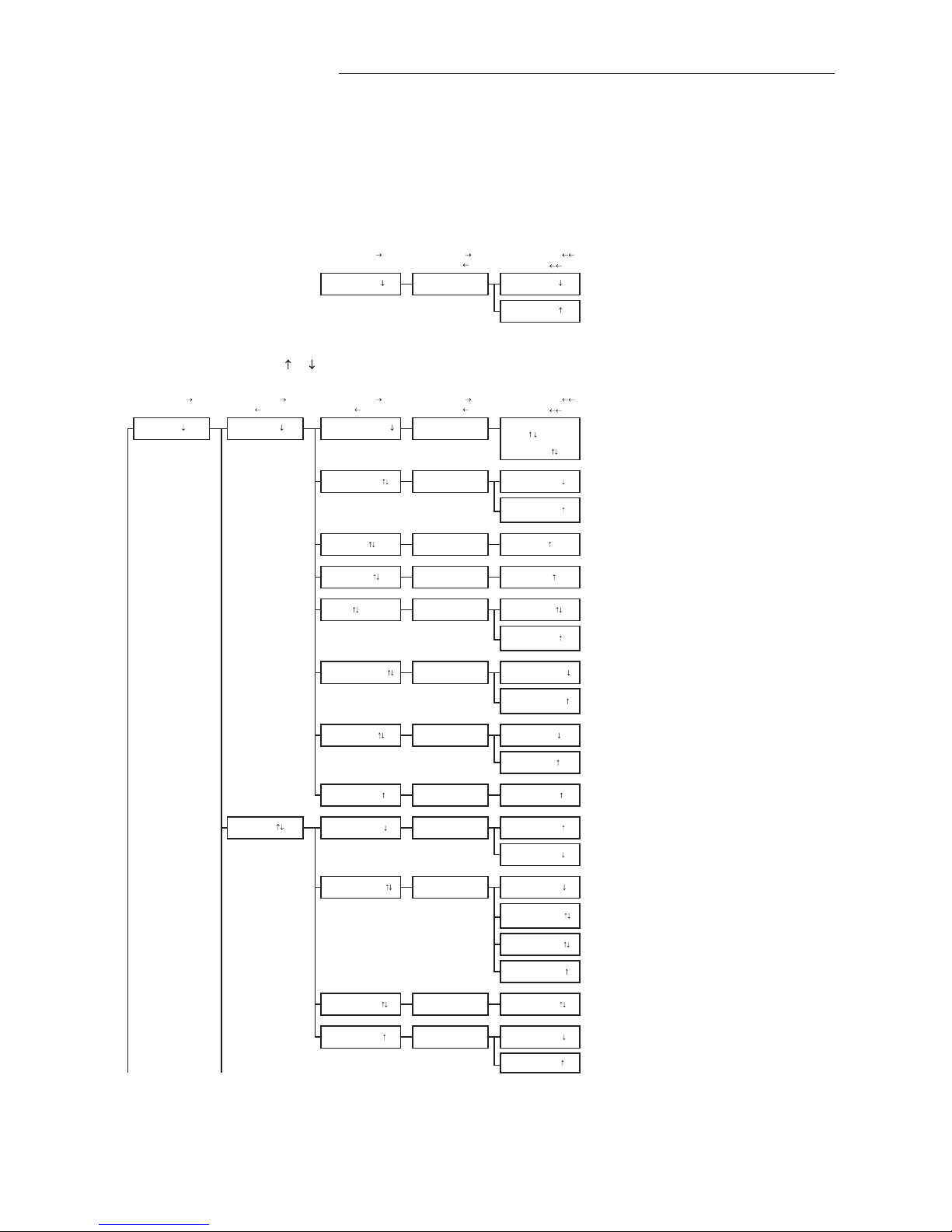
APPENDIXA‐
ADVANTAGE3‐ SETUPMENUS
SYSTEM OF UNITS MENU
Simultaneously depress/release ENTER + ESC keys during normal operation to select
* Factory Default/Current Setting
Enter (move ) Enter (move ) Enter (action, move )
Esc (normal oper.) Esc (move )Esc (move )
ACTION
SETUP MENU
Simultaneously depress/release + keys during normal operation to select
* Factory Default/Current Setting
Enter (move ) Enter (move ) Enter (move ) Enter (move ) Enter (action, move )
Esc (normal oper.) Esc (move or prev setting) Esc (move or prev setting) Esc (move )Esc (move )
ACTION
Only when AIRFLOW=ACT
TO PART 5 'A' TO PART 2
AUTO forces a re-read of the one-wire value. (AUTO not available if area value has not been
written into one-wire chip).
O
Integration samples for LCD.
SET LCD DSPL? LCD DSPL=OFF
LCD DSPL=FLOW
Set what is displayed on LCD.
LCD DSPL=BOTH
*LCD DSPL=BOTH
LCD UM=AFPM
*LCD INTG=100 SET LCD INTG? LCD INTG=100
GENERAL *NAME={unit serial#} SET NAME ?
*LCD TRBL=ON SET LCD TRBL? LCD TRBL=OFF
ON FAIL=HI
*EXT CABLE=0 SET EXT CABLE? EXT CABLE=0
SETUP
*AIRFLOW=ACT SET AIRFLOW?
AIRFLOW=STD
SET ALT?
Set the airflow measurement to ACTUAL units (AFPM/ACFM)
Set the airflow measurement to Standard units (SFPM/SCFM)
AIRFLOW=ACT
Custom LCD Flow Text: Blinking prompt at position of the selected character. Character is
selected using the up and down arrows and then ENTER to accept and move cursor forward
(right); ESC moves the cursor back (left). Use space characters
for blank or unwanted text.
Instruction text:
"USE AND ENT"
then:
NAME= _
IP/SI=IP SYS
*LCD UM=ACFM
IP/SI=SI SYS
*LLIMIT=0
DISPLAY
ALT=0
*ON FAIL=LO SET ON FAIL?
*ALT=0
Set LCD airflow display units to CFM or FPM. (Note: A-ACT or
S-STD measurement prefix is set by AIRFLOW= setting above).
This is always a velocity value.
*AREA= {from setup}
*TEMP METH=WGT
SET IP/SI ?
AREA=xx.xx
*IP/SI=IP SYS
SET AREA?
ON FAIL=LO
Set system of units to I-P (FPM, CFM, sq.ft., ºF)
or Set system of units to S.I. (MPS, LPS, sq.M., ºC).
NOTE:
Changing IP/SI SYS resets alarm settings and scaling values.
Set the altitude above sea level for flow correction: 0 to 18,000 ft.
LLIMIT=0
SET LCD UM? LCD UM=ACFM
SET TEMP METH?
SET LLIMIT?
AREA=AUTO
Enter length of extension cable.
Note: Value is from one-wire but can be overridden.
Set whether or not TROUBLE will display on LCD during a trouble condition.
TEMP METH=WGT Set temperature output for velocity weighted average of temperature sensors.
TEMP METH=AVG Set temperature output for mathematical average of temperature sensors.
Sets transmitter analog output state in the event of a major fault (all sensor failure) expressed
as HI for full scale analog output or LO as minimum scale analog output.
LCD DSPL=TEMP
LCD TRBL=ON
O

EBTRON • 1663 Hwy. 701 S., Loris SC 29569 • Toll Free: 800.2EBTRON (232.8766) • Fax: 843.756.1838 • Internet: EBTRON.com 19
GOLD SERIES GTC116 TRANSMITTER
a measurable difference!
EBTRON
IG_GTC116_R3A
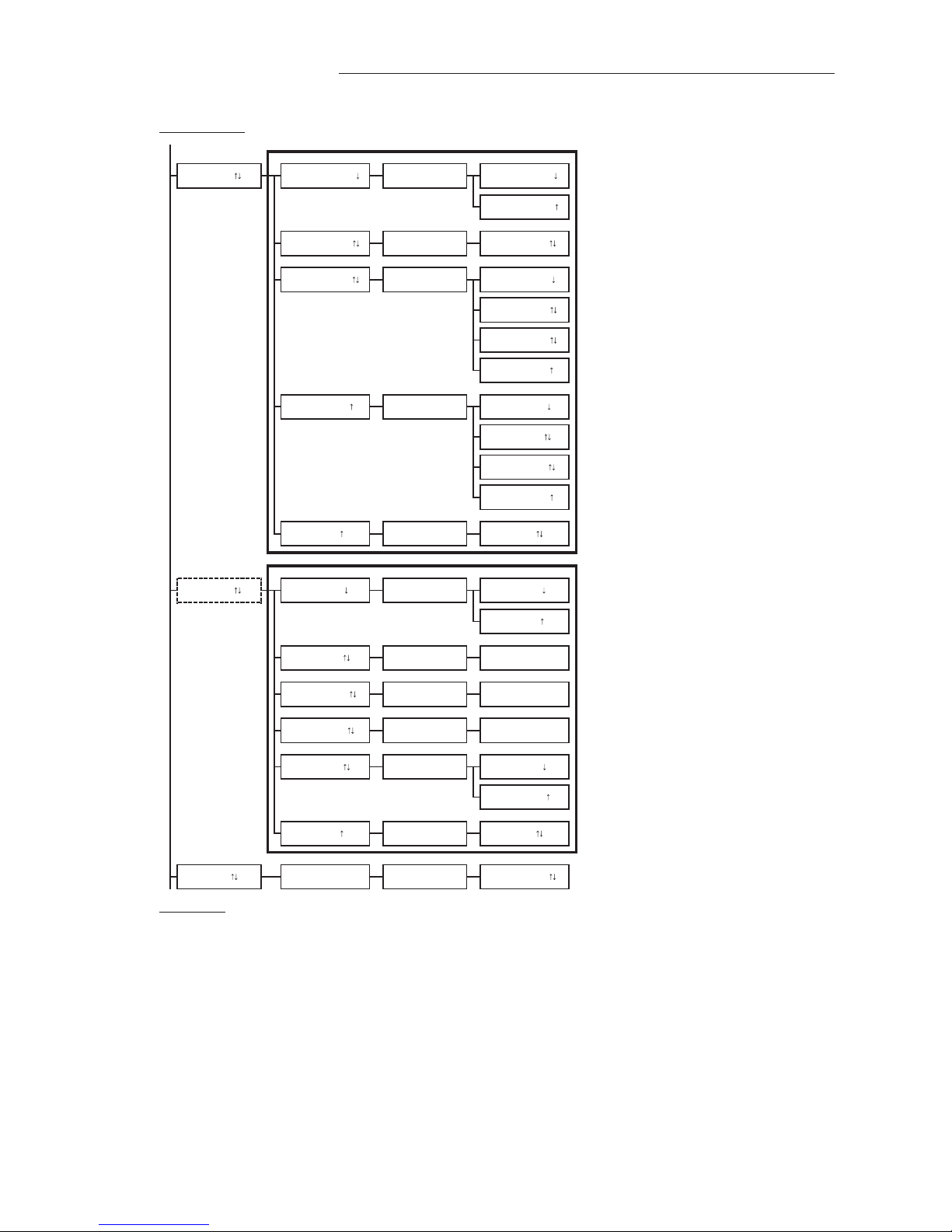
FROM PART 1
Analog cards only
if AO1 SGNL=mA
if AO1 SGNL=VDC
AO2 output is assigned as temperature output.
if AO2 SGNL=mA
if AO2 SGNL=VDC
if AO2 CFG=TEMP
if AO2 CFG=ALRM or TRBL
TO PART 3
NO FAULT = HI
Set AO1 output units to FPM or CFM. (Note: A-ACT or
S-STD measurement is set by AIRFLOW= setting above).
*AO2 MS=-20 SET AO2 MS? AO2 MS=-20
*AO2 FS=160
AO2 RNGE=0-5
*AO2 UM=F AO2 UNITS FIXED The text "AO2 UNITS FIXED" flashes to indicate that this setting is fixed and cannot be
modified.
*NO FAULT = HI SET NO FAULT? NO FAULT = LO
AO2 RNGE=FIXED The text "AO2 RNGE=FIXED" flashes to indicate that this setting is fixed and cannot be
modified.
*AO2 RNGE=0-10 SET AO2 RNGE? AO2 RNGE=0-10 Set analog output range (VDC) for AO2.
SET AO2 FS?
Integration samples. Also same as network integration.
*AO2 ASGN=TEMP SET AO2 ASGN? AO2 ASGN=TEMP
AO2 ASGN=ALRM
*A02 SGNL=mA SET SW2 ON PCB Display initially shows the current SW2 PCB switch setting (VDC or mA) for AO2. Pressing
enter displays "SET SW2 ON PCB" prompt to confirm SW2 PCB setting.
AO2 output is assigned as an airflow alarm output.
Refer to ALARM settings (part 4).
AO2 FS=160
*AO1 FS=5000 SET AO1 FS? AO1 FS=5000
AO2 ASGN=TRBL
*AO1 INTG=30 SET AO1 INTG? AO1 INTG=30
SET AO1 RNGE? Set analog output range (VDC) for AO1.AO1 RNGE=0-10
AO1 RNGE=0-5
*AO1 UM=AFPM SET AO1 UM?
*A01 SGNL=mA SET SW1 ON PCB Display initially shows the current SW1 PCB switch setting (VDC or mA) for AO1. Pressing
enter displays "SET SW1 ON PCB" prompt to confirm SW1 PCB setting.
*AO1 RNGE=4-20 AO1 RNGE=FIXED The text "AO1 RNGE=FIXED" flashes to indicate that this setting is fixed and cannot be
modified.
The text "AO1 ASGN FIXED" flashes to indicate that this setting is fixed and cannot be
modified.
ANALOG OUT *AO1 ASGN=FLOW
AO1 UM=AFPM
AO1 ASGN FIXED
AO2 output is assigned as a transmitter trouble alarm indicating that a sensor or transmitter
fault has occurred.
Sets AO2 alarm/trouble output state when no fault condition is present, expressed as HI (full
scale analog output) or LO (minimum scale analog output).
AO1 UM=ACFM
Set full scale for AO1. FS default value is dependent on probe type connected.
O
*AO1 RNGE=0-10
*AO2 RNGE=4-20
O
Set AO2 minimum scale.
Set AO2 full scale.
20 EBTRON • 1663 Hwy. 701 S., Loris SC 29569 • Toll Free: 800.2EBTRON (232.8766) • Fax: 843.756.1838 • Internet: EBTRON.com
GOLD SERIES GTC116 TRANSMITTER
a measurable difference!
EBTRON
IG_GTC116_R3A
FROM PART 2
GTC only GTC configuration
Enter network address.
Set network baud rate.
Option for MODBUS only
Set MODBUS parity type.
Option for BACNET only
Set network device instance number.
GTM only GTM configuration
TO PART 4
Enter IP address, use (up/down arrow) buttons to select value and press ENT to move to right
and ESC to move to left.
Enter subnet mask, use (up/down arrow) buttons to select value and press ENT to move to
right and ESC to move to left.
Enter gateway IP address, use (up/down arrow) buttons to select value and press ENT to move
to right and ESC to move to left.
Set BACnet IP or Ethernet protocol.
SET IP?
SET NETADDRESS?
NETWORK
*IP=10.0.0.1
EB-LINK
NETWORK
O
O
*NETOUT=BACNET SET NETOUT? NETOUT=BACNET Set network protocol type.
PARITY=ODD
NETBAUD=38400
*NETDI=2 SET NETDI?
010.000.000.001
*NETBAUD=76800 SET NETBAUD? NETBAUD=76800
*PARITY=EVEN SET PARITY? PARITY=EVEN
Set DHCP to ON or OFF.
DHCP=ON
NETBAUD=19200
NETBAUD=9600
BACNET=IP
PARITY=NONE2
*BACNET=IP SET BACNET?
*MASK=255.255. SET MASK? 255.255.255.000
BACNET=ETH
*GATE=10.0.0.. SET GATEWAY? 010.000.000.010
NETDI=2
*DHCP=OFF
PARITY=NONE1
NETOUT=MODBUS
*NETADDRESS= 2 NETADDRESS=2
SET DHCP? DHCP=OFF
*EB-LK INTG=300 SET EB-LK INTG? EB-LK INTG=300 EB-Link integration samples.
*NETDI=2 SET NETDI? NETDI=2 Set network device instance number.
Table of contents
Other Ebtron Transmitter manuals


Popular Transmitter manuals by other brands


RKI Instruments
RKI Instruments 65-2330RK Operator's manual

Becker
Becker Centronic EasyControl EC315 Assembly and operating instructions

AFi
AFi MT-3340-12VDC instruction manual

DRC
DRC JJIFA-IR4TX instruction manual

Sanyo
Sanyo POA-HDTM01 owner's manual

Connevans
Connevans IR Classmate Reference & installation manual