Sentinel SolarCheck User manual

Sentinel Performance Solutions Ltd, The Heath Business & Technical Park
Runcorn, Cheshire, WA7 4QX T: +44 (0) 1928 588330 F: +44 (0) 01928 588368
Page 1 of 4 june-10
Technical Information
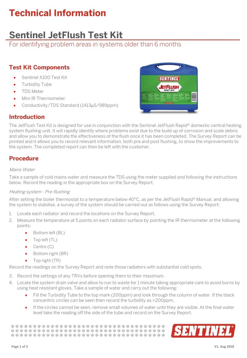
Sentinel SolarCheck Test Kit Instructions
Test Kit Components
•Compass
•Radiator key
•Pack of pH Papers (Range 6.0 – 10.0)
•Infrared Thermometer
•Refractometer
•Plastic Dropper
•Sample Bottle
Introduction
The SolarCheck Test Kit has been designed
specifically for use, either when installing a solar
heating system, or when subsequently
performing routine checks. After the initial
installation the test kit will allow you to check the
orientation of the solar panels to ensure
maximum solar energy collection and also to
confirm the level of antifreeze present in the
thermal fluid.
During routine service visits it is important to
continue to monitor the condition of the
antifreeze/thermal fluid. After a number of years
in the system, the thermal fluid will need to be
replaced. The test kit allows you to determine
exactly when the replacement is required.
Recommended Service Visit
Procedures
1. If access is available measure the
temperatures at the top and bottom of the
solar plate collector using the Infrared
Thermometer as described in the following
instructions. The temperatures should then
be recorded on the “SolarCheck Survey
Sheet”.
2. Measure the temperatures of the inlet and
outlet thermal fluid pipework as it enters and
leaves the hot water storage tank and again
record on the “SolarCheck Survey Sheet”.
3. Using the radiator key, take a sample of the
thermal fluid from a suitable drain valve on
the system. Discard the first bottleful and
refill the bottle. Take appropriate care to
avoid burns by using heat resistant gloves if
it is appropriate to do so.
4. Record the appearance of the thermal fluid
on the “SolarCheck Survey Sheet”. Ideally it
will be a clear liquid with the viscosity of
water. If Sentinel R100 Solar Thermal Fluid
has been used it will be pale blue in colour.
After a period of operating at extreme
temperatures or under stagnant conditions
the thermal fluid can become cloudy and the
colour changes to dark brown. The viscosity
also increases.
5. Measure the antifreeze content using the
refractometer as described in the following
instructions and record on the “SolarCheck
Survey Sheet”. Ideally the antifreeze content
will be 35 - 40% that will provide frost
protection down to at least –25oC*. If the
antifreeze content is less than 35% it
indicates that some dilution has occurred
with mains water and a leak has occurred
into the system diluting the thermal fluid.
Dilution of the thermal fluid with water must
NEVER take place. The recommendation
would be to check for the leak, repair and
then replace the thermal fluid using Sentinel
R100 Solar Thermal Fluid.
6. Measure the pH of the thermal fluid using the
pH papers as described in the following
instructions. The recommendations for
different pH levels are as follows:

Sentinel Performance Solutions Ltd, The Heath Business & Technical Park
Runcorn, Cheshire, WA7 4QX T: +44 (0) 1928 588330 F: +44 (0) 01928 588368
Page 2 of 4 june-10
Technical Information
Measured pH Level Recommended Actions
Greater than 8.5
The cleaner has not been flushed from the system correctly.
Ideally the system should be drained, flushed and refilled
with Sentinel R100.
7.5 - 8.5 pH is satisfactory. No action required.
7.0 – 7.4 pH is below ideal and more frequent checks are
recommended
Less than 7.0 pH is too low indicating that the thermal fluid has
deteriorated beyond an acceptable condition. System must
be drained and cleaned with a suitable system cleaner.
Refill with Sentinel R100
7. After a clean has been performed with a
suitable cleaner, measure the pH of both the
mains water and the final flushing water.
Ensure the pH of the final flushing water
is the same as the mains water.
Compass
The compass can be used to check the
orientation of the solar plate collectors. Ideally
they should be installed such that they are facing
in a southerly direction or as close to it as
possible.
Instructions for use of Infrared
Thermometer
Operation
1. Point the unit at the surface to be measured.
You must ensure that the detection area you
want to measure is larger than the light spot
size to get a correct reading. The light spot is
used for aiming at the target.
2. Press the button and the temperature reading
will be updated on the LCD. When the
operator releases the button, the reading will
automatically be held on the LCD for 10
seconds. After 10 seconds the thermometer
will power down.
3. The temperature units can be changed by
using the oC/oF switch.
Measurement Notes
•If the surface of the object under test is
covered in oil, grime etc clean before
taking measurements.
•If the surface of the object is highly
reflective, apply masking tape to the
surface before measuring.
•Steam, dust, smoke can obscure
accurate measurements.
Battery Replacement
When the low battery symbol appears on the
LCD, replace the meter’s 1.5V batteries. Detach
the battery compartment cover by pushing the
engraved pattern on the handle and pull down.
Replace the 1.5V x 2 batteries with new ones
and replace the battery compartment cover.

Sentinel Performance Solutions Ltd, The Heath Business & Technical Park
Runcorn, Cheshire, WA7 4QX T: +44 (0) 1928 588330 F: +44 (0) 01928 588368
Page 3 of 4 june-10
Technical Information
Instructions for use of the
Refractometer
Operation
Calibration Check
1. Open the daylight plate and place 2-3 drops
of distilled water on the blue glass prism
using the plastic dropper. Close the daylight
plate so that the water spreads across the
entire surface of the prism without air bubbles
or dry spots.
2. Allow the sample to rest on the prism for
approximately 30 seconds to allow the
sample to adjust to the temperature of the
refractometer.
3. Hold the daylight plate in the direction of a
light source and look into the eyepiece. A
circular field with graduations will be visible.
(You may have to focus the eyepiece to
clearly see the graduations). The upper
portion of the field should be blue and the
lower portion should be white.
4. If the boundary between the blue and white
does not meet on the zero graduation, which
is at the bottom of the propylene glycol scale,
then calibration will be required. Adjust the
calibration screw until the boundary meets at
the zero graduation.
Sample Check
1. Ensure that the sample is cooled to ambient
temperature and repeat steps 1 – 3 above.
Take the reading at the point where the blue
and white boundary occurs on the propylene
glycol scale. This will represent the antifreeze
content of the thermal fluid.
Warning – Maintenance
1. Do not expose the instrument to damp
working conditions and do not immerse the
instrument in water. If the instrument
becomes foggy, water has entered the body
of the instrument and the supplier needs to
be contacted.
2. Do not measure abrasive or corrosive
chemicals with this instrument. They can
damage the prism’s coating.
3. Clean the instrument between each
measurement using a soft, damp cloth.
Failure to clean the prism on a regular basis
will lead to inaccurate results and damage to
the prism’s coating.
4. This is an optical instrument. It requires
careful handling and storage. Failure to do so
can result in damage to the optical
components and its basic structure.
Instructions for use of the pH Sticks
1. Briefly dip the pH stick in the sample of
thermal fluid. If the sample is weakly buffered
leave test stick in the sample until colour no
longer changes.
2. Compare the colour of the two pads on the
bottom of the strip with the chart on the side
of the pack.
SolarCheck Survey Sheet
The “SolarCheck Survey Sheet” is available free
on the Sentinel Performance Solutions Ltd web
site at www.sentinel-solutions.net.

Sentinel Performance Solutions Ltd, The Heath Business & Technical Park
Runcorn, Cheshire, WA7 4QX T: +44 (0) 1928 588330 F: +44 (0) 01928 588368
Page 4 of 4 june-10
Technical Information
* Frost Protection
Please note that the frost protection figure quoted
in the Test Kit instructions refers to a ‘burst
protection’ at which propylene glycol
concentration is sufficient to prevent bursting of
pipework but not necessarily high enough to
maintain the fluid in a pumpable state. This figure
is the ‘Setting Point’ as measured using the DIN
51583 method. The ‘Setting Point’ is the
temperature at which the fluid solidifies.
The temperature figure read from the
refractometer corresponding to the percentage
glycol figure is the onset of the freezing point as
measured using the ASTM D1177 method. For a
propylene glycol/water mixture, at temperatures
between its ‘Freezing Point’ and its ‘Setting
Point’, the mixture becomes progressively more
difficult to pump. A comparison chart of ‘Freezing
Point’ and ‘Setting Point’ for propylene
glycol/water mixtures is shown below.
% Propylene Glycol (v/v)
0
5
10
15
20
25
30
35
40
45
50
Freezing Point (°C)
0
-2
-4
-6
-8
-11
-13
-17
-21
-27
-34
Setting Point (°C)
0
-2
-5
-8
-10
-14
-17
-22
-28
-37
-50
Other Sentinel Test Equipment manuals
Popular Test Equipment manuals by other brands

Megger
Megger SR-98 instruction manual

OptiSense
OptiSense PaintChecker Mobile user manual
VOLTCRAFT
VOLTCRAFT LiPo Checker Pro 2-8S operating instructions

Commercial Electric
Commercial Electric MS603 Use and care guide
Soundbyte Solutions
Soundbyte Solutions Parrotplus instructions
Bante Instruments
Bante Instruments WXG-4 user manual
