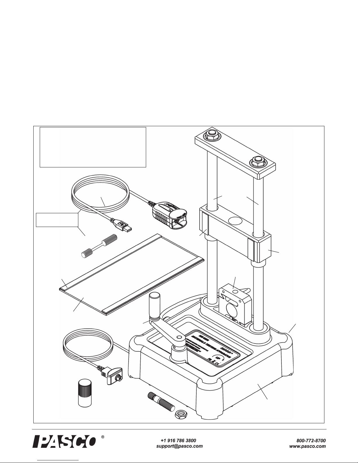
Materials Testing Machine Operation
4012-13762D
interface for data recording, and then turning the crank to
apply tension (stretching), compression (squeezing), bend-
ing, or shearing (cutting) forces to the test item.
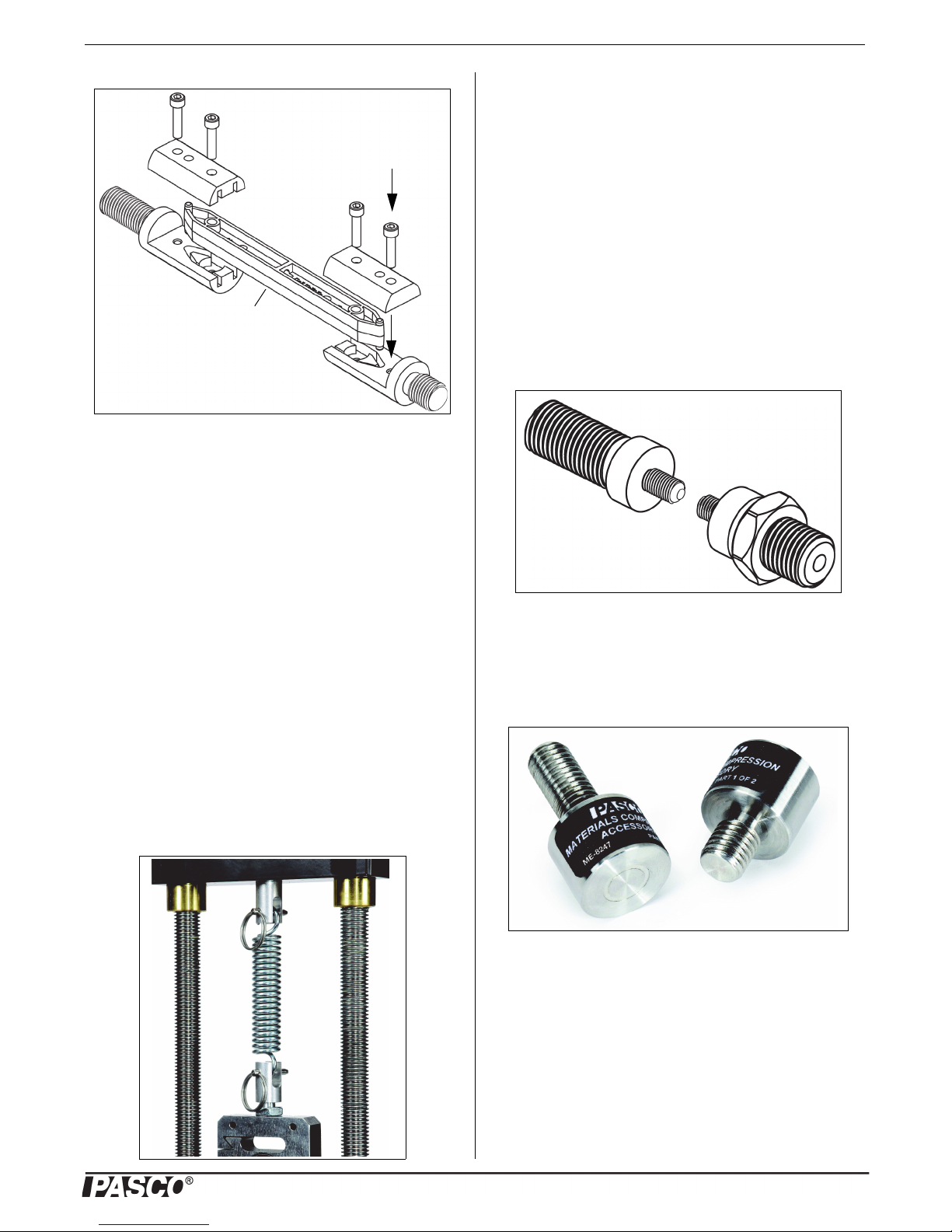
ME-8229 MTS Storage Base
Secure the Materials Testing Machine
There are two holes through the base of the Materials Testing
Machine that can be used for bolting the Machine to a sturdy
support. The two 6 millimeter (mm) diameter holes are 15
centimeters apart; one on either side of the label.
Bolting the Machine will avoid the problem of the Machine
moving during a sample test. The Materials Testing System
Storage Base (ME-8229) is designed for two purposes: pro-
vide a sturdy base to which the Materials Testing Machine
can be bolted, and serve as a storage place for accessories,
tools, and other items in the Comprehensive Materials Test-
ing System.
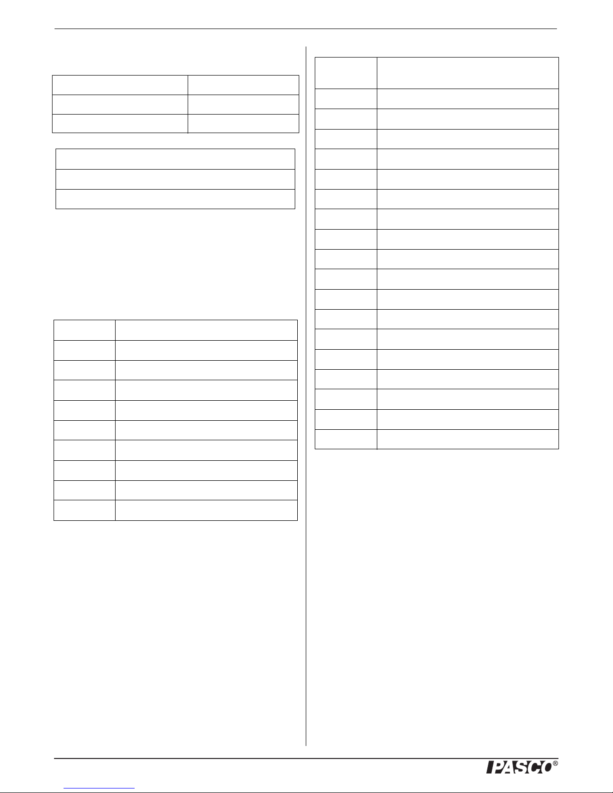
The Storage Base includes two screws and two washers and
has two threaded holes that match the spacing of the holes in
the Materials Testing Machine base. Place the Materials
Testing Machine on the Storage Base. Put the washers on the
screws, and put one screw through a hole in the base of the
Materials Testing Machine. Align the screw with the
threaded hole in the Storage Base, and tighten the screw
using your fingers. Put the other screw through the base and
align it with the other threaded hole. Use a 7/16 inch (11
mm) wrench to tighten the screws in place. Use C-clamps to
fasten the Storage Base to a sturdy table or bench. An option
is to bolt the Machine directly to a table or bench as shown.
The Storage Base has through holes at each of its corners.
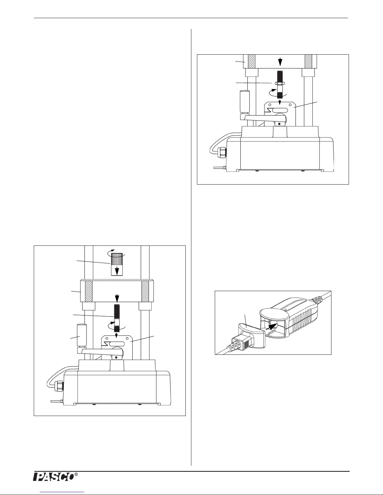
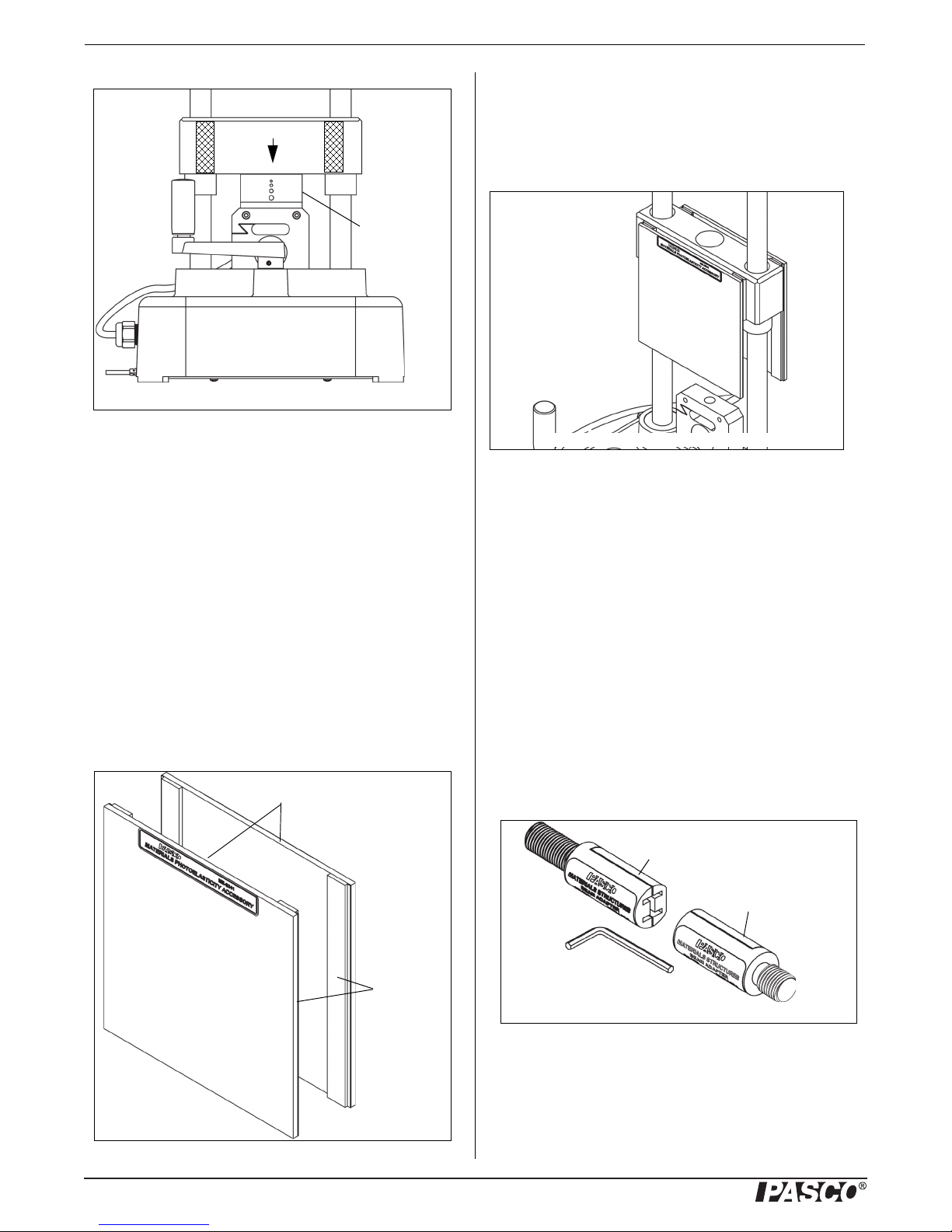
Calibration Setup
The calibration rod and nut can be used for calibrating the
Materials Testing Machine for compression or tension. The
PASCO Capstone data collection software includes a “cali-
bration wizard” that allows the calibration information -
called a “compliance calibration” - for the Materials Testing
Machine to be stored for later use. (PASCO Capstone is pro-
vided in the ME-8230 Materials Testing System.)
Lab 02: Compliance Calibration Tutorial
NOTE: A PASCO Capstone workbook file about compliance
calibration is available to download from the PASCO web
site. Go to www.pasco.com and enter “Materials Testing
System” in the Search window. In the web page that opens,
select Materials Testing System. Click “Sample Labs” and
then download the ZIP file for Lab 02.
Information covered in the Compliance Calibration Tutorial
includes:
• How a compliance calibration works.
• How to create, save, and delete calibrations.
• Hints and practice in making an accurate calibration.
Reason for Calibration
The reason for the compliance calibration procedure is this:
if the Materials Testing Machine were perfectly rigid it
would give completely accurate measurements of force and
displacement. However, the Machine is not perfectly rigid.
To correct for the fact that the Machine “flexes” slightly, the
stiffness of the Machine is characterized and a calculation is
performed in the software to adjust the raw position data and
compute the displacement that is due only to the distortion of
the sample being tested. The compliance calibration infor-
mation for the Machine can then be stored within the
Machine or stored in a Capstone file.
The calibration rod will not change shape significantly under
tension or compression. This means that any displacement
measured when the calibration rod is used is due to the flex-
ing of the Materials Testing Machine itself.
For example, the sample graph shows that the Machine
flexes 0.2 mm per 3,500 newtons of force when the calibra-
tion rod is stretched. If you use the Machine to stretch a
material sample, then the “flex” amount of 0.2 mm per 3,500
N would need to be subtracted.
Storage Base
Sturdy support* C-clamp*
Bolt*
Nut*
(*Items not included)