SENTRONIC AkuSense AS-11C User manual
Contents
AS-11C User Manual
V.1
056 222 38 18 mailbox@sentronic.com www.sentronic.com
SENTRONIC AG
2
AS-11C User Manual
Document Description
Table 1.1 Product basic information
Working environment
Indoor
Light source
Infrared laser (905nm)
Laser safety Class
Class 1 (GB 7247.1-2012, human eye safety)
Scan angle range
360°
Scanning frequency
12.5Hz
Scanning angle resolution
0.5°
Measuring range
0.1m - 20m
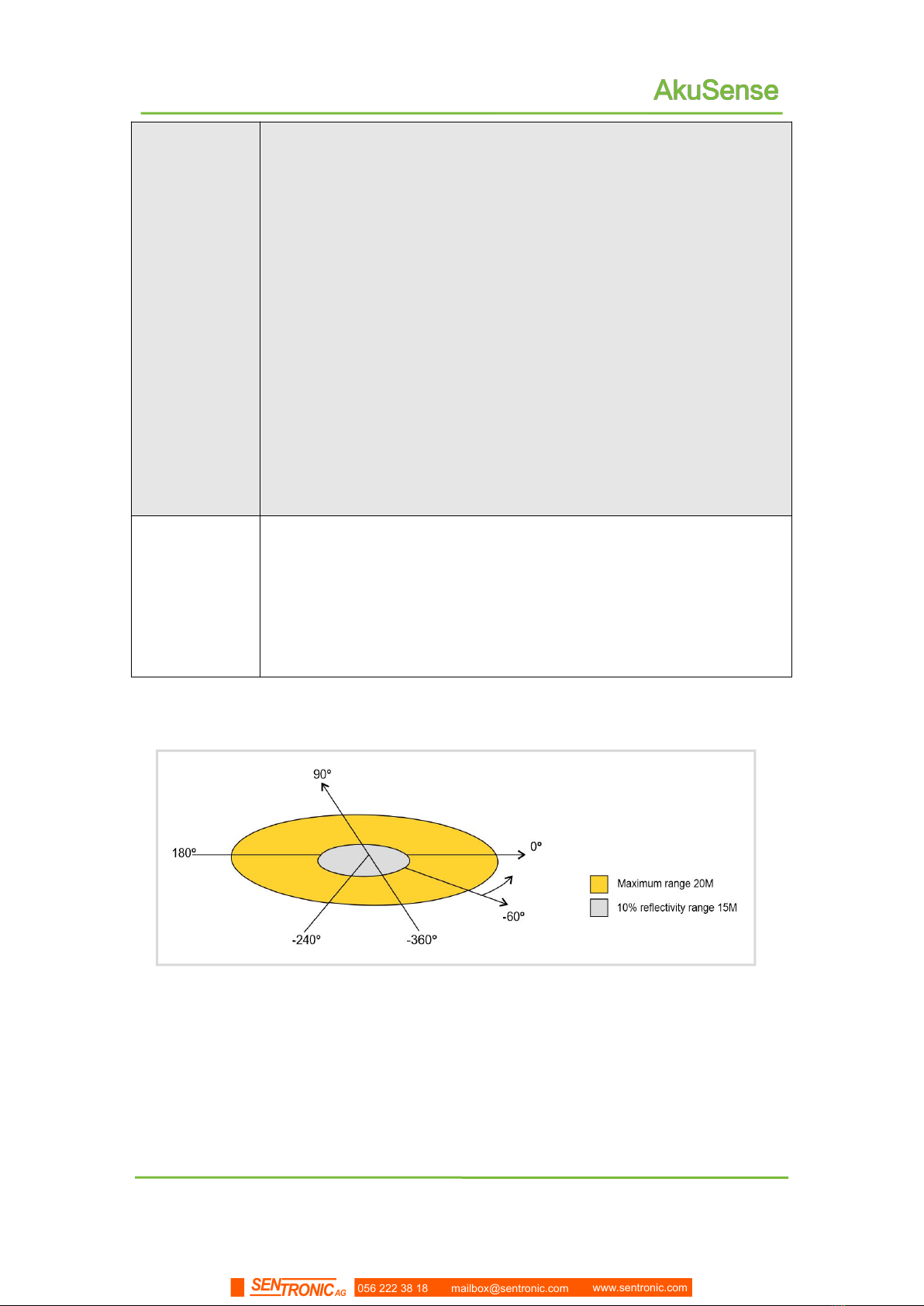
10% reflectance range
15m
Built-in application
Regional monitoring
Operating Voltage
DC 12V—28V
Power consumption
3.8W@DC24V
Outer covering protection range
IP65(GB 4208-2008)
Weight
0.5Kg
Dimensions(L╳W╳H)
86 ╳85 ╳59(mm)
Working temperature range
-10℃~ +45℃
Storage temperature range
-30℃~ +70℃
Ambient illumination range
0lux ~ 70,000lux
Attention
Attention
For complete technical information, please read "10
Technical Specifications."
Please use the "LiDAR Diagnostic and Configuration
Software (FILPS)" to diagnose and configure the AS-11C.
How to use FILPS Please read the "LiDAR Diagnostic and
Configuration Software (FILPS) User's Manual".
056 222 38 18 mailbox@sentronic.com www.sentronic.com
SENTRONIC AG
3
AS-11C User Manual
Basic operation and precautions
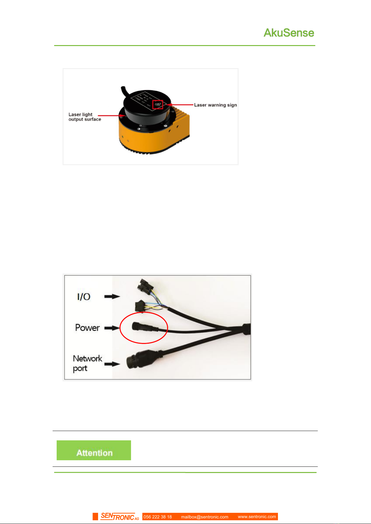
Figure 2.1 laser light emitting surface and laser warning sign
2.6 Power supply and quick start and stop
AS-11C supply power through the DC002 round waterproof power socket in the
interface cable on the side of the equipment, as shown in "Figure 2.2 power socket"; The
power supply voltage is required to be DC12V - 28V, under normal operation, the power
consumption is 3.8W and the maximum power consumption is 4.3W. Please provide
power according to the above standards when using.
Figure 2.2 power socket
Please read the "10.1 Data Manual" in detail to understand
AS-11C complete requirements for power supply. Users
should follow the local regulations and make necessary
056 222 38 18 mailbox@sentronic.com www.sentronic.com
SENTRONIC AG
5
Product description
AS-11C User Manual
3.Product description
3.1 Deliveries
AS-11C product deliverables are shown in "Table 3.1 product deliverables list”
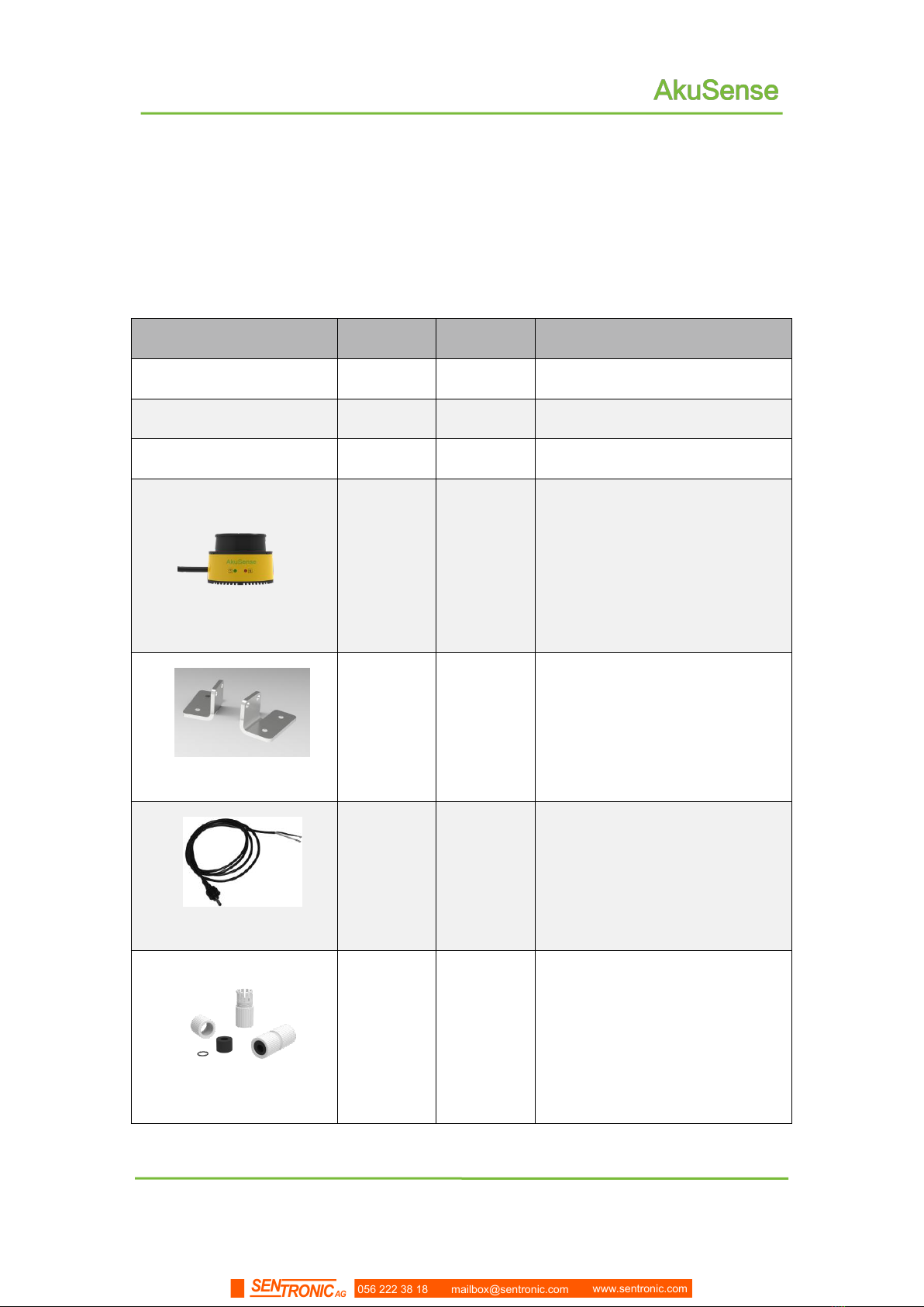
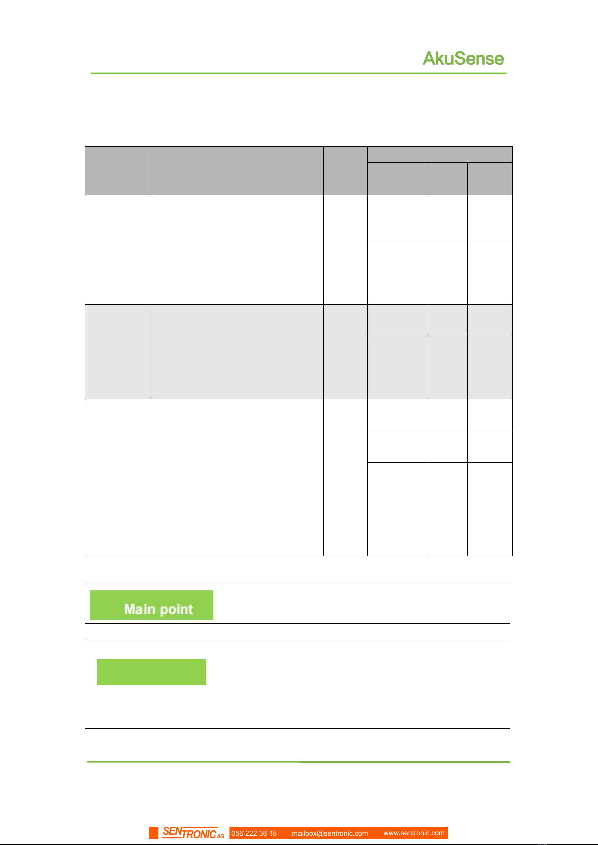
Table 3. 1 Product deliverables list
Deliverables
qty
unit
Description
User Manual
1
piece
Certificate
1
piece
Warranty Card
1
piece
AS-11C
1
piece
Laser LiDAR
AS-11C-AT
1
pair
Simple bracket
AS-11C-EC
1
piece
Power cable
AS-11C-WJ
1
piece
Network cable crystal head
waterproof jacket
056 222 38 18 mailbox@sentronic.com www.sentronic.com
SENTRONIC AG
6
Product description
AS-11C User Manual
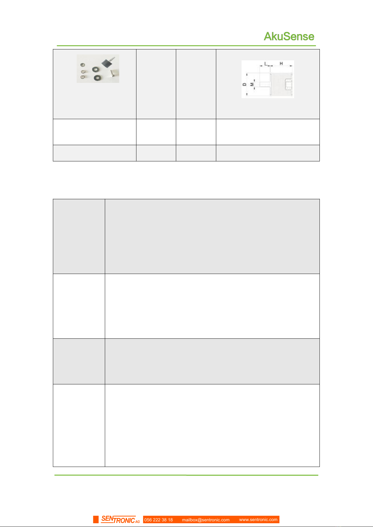
Shock absorber screws,
hexagon socket screws,
washers and nuts
6
set
M4╳D15╳H10╳L8
Hexagon socket screws
and gaskets
6
set
M4*8
Simple installation tool
1
piece
M4 hexagon wrench
3.2 Product characteristics
Table 3. 2 Product characteristics
Working
environment
Power supply voltage range: DC 12V–28V;
Low power consumption: 3.8W@DC24V
Comprehensive working ability: anti-dirt, anti-glare.
IP65 enclosure protection level.
-10 ℃~ + 45 ℃working temperature range
Distance
measurement
Pulsed flight time measurement technology system
905nm infrared laser measurement, class 1 safety laser (GB
7247.1-2012, human eye safety).
The maximum range is 20 meters, and the range of 10% reflectivity
is 15 meters.
Scanning
Use mechanical scanning
360° scan range, 0.5° scan angle resolution
12.5Hz scanning frequency
Device
interface
Ethernet interface
Function: device configuration / measurement data output /
monitoring signal output
I/O interface
Function: peripheral control, area monitoring function operation control
and monitoring signal output, Device ready indication
056 222 38 18 mailbox@sentronic.com www.sentronic.com
SENTRONIC AG
7
Product description
AS-11C User Manual
Built-in
application
Regional monitoring
Monitoring mode: point monitoring / target width monitoring /
contour monitoring;
16 modifiable preset area groups, support background contour
self-learning
Up to 16 concurrent work area groups
Can detect targets of any shape and support normal target
self-learning;
Disarming and forced alarms via I/O input terminals;
Monitor the signal through the I/O output terminal and Ethernet
(TCP message) output area.
No PC configuration is supported.
Availability
Reliability
Anti-strong light, anti-dirt
Self-checking capability of equipment failure, including transparent
cover, dirty cover, temperature over-standard;
The device self-test information is output through the indicator light
and TCP message.
Figure 3.1 Measuring Coordinate System/Scan Range/Range
056 222 38 18 mailbox@sentronic.com www.sentronic.com
SENTRONIC AG
9
Product description
AS-11C User Manual
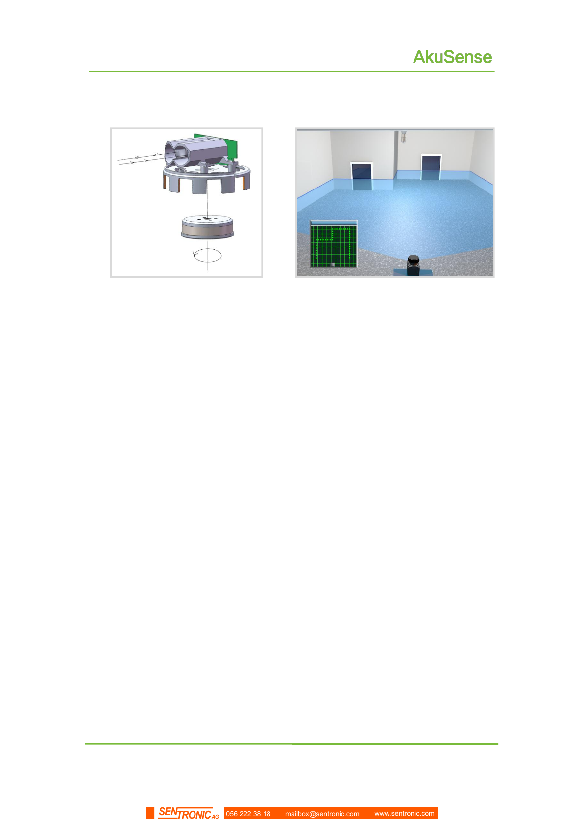
Figure 3.3 scanning measuring mechanism
Figure 3.4 Two-dimensional Cross-section
Scanning
3.3.3 Scene measurement and regional monitoring
By analyzing and processing the distance data obtained by two-dimensional scanning,
the application system can measure and monitor the scene, detect and locate various
targets in the scene, measure its shape, and finally output the analysis results according
to the application requirements. For example, alarm and guidance.
The AS-11C has a built-in area monitoring function, which is mainly used for indoor AGV
obstacle avoidance and other Movement applications. It can also be used for indoor
security protection, which can achieve perimeter prevention, intrusion monitoring, contour
monitoring and other functions. With background self-learning ability, you can configure
the area monitoring function through the "Lidar Diagnostic and Configuration Software
(FILPS)" or set the monitoring arming conditions through the I / O input terminal. The
monitoring results are output through TCP network messages, and also real-time output
through AS-11C's I / O output terminal.
056 222 38 18 mailbox@sentronic.com www.sentronic.com
SENTRONIC AG
11
Product description
AS-11C User Manual
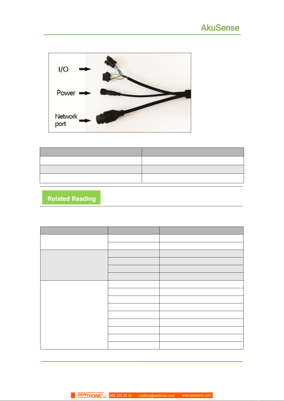
Figure 3.7 Equipment Interface
Table 3. 3 Device Interface
Socket
Number of cores
Power interface
2
Ethernet interface
4
I/O interface
9
Table 3. 4 Device Interface Signal Definition
Interface
Signal
Explanation
Power interface
Vs
Power
GND
GND
Ethernet interface
RX+
Data reception positive end
RX-
Data receiving negative end
TX+
Data reception positive end
TX-
Data receiving negative end
I/O interface
IN1
Universal input 1# positive end
IN2
Universal input 2# positive en
IN3
Universal input 3# positive end
IN4
Universal input 4# positive end
GND IN
Universal input GND
OUT1
Universal output 1# positive end
OUT2
Universal output 2# positive end
OUT3
Universal output 3# positive end
OUT4
Universal output 4# positive end
Please read the "10.1 Data Manual" for the electrical
characteristics of each socket ".
056 222 38 18 mailbox@sentronic.com www.sentronic.com
SENTRONIC AG

14
AS-11C User Manual
Applications
4 Applications
4.1 Technical Application
In practical application, the range and measurement effect of AS-11C are affected by
many environmental factors, which need special attention and appropriate measures to
deal.
AS-11C actual range of a specific target is affected by the following factors:
Actual diffuse reflection rate:It refers to the actual diffuse reflection rate of the
part of the target surface exposed to the laser spot of measurement emitted by
the AS-11C. The actual diffuse reflection rate is not only related to the material,
but also to the surface orientation. The higher the actual diffuse reflectance, the
farther the actual range.
Reflection area:The area covered by the laser spot on the target surface. The
larger the coverage area, the farther the actual measurement distance.
Dirt degree of light-transmitting cover:The dirt of the AS-11C's light-transmitting
cover will cause a decrease in the light-transmitting performance. When the
transmittance drops to 60%, the measurement capability may be completely
invalid.
Environmental conditions:The actual measurement capability of AS-11C is also
affected by environmental conditions. The light transmission capability of the
atmosphere is poor, and the actual measurement capability of the AS-11C is low.
Under extreme smoke and fog conditions, the measurement capability will be
completely invalid.
Main point
When using AS-11C to build an application system, it is
necessary to set the working range of the AS-11C on the basis
of comprehensive consideration of various application
demand factors, which include:
Minimum actual diffuse reflection rate and minimum
size of the target to be discovered
AS-11C the cleanliness of the working environment
and whether it can be maintained in time, such as
cleaning the transparent cover.
056 222 38 18 mailbox@sentronic.com www.sentronic.com
SENTRONIC AG

15
AS-11C User Manual
Applications
4.1.2 Relationship between spot diameter and target size
The laser beam emitted by the AS-11C has a certain divergence angle. In the horizontal
direction, the divergence angle is 10mrad, and in the vertical direction, the divergence
angle is 2mrad; At a specific measuring distance, the relationship between the spot size r
of the AS-11C and the measurement distance d is:
rH= r0+ αH·d
rV= r0+ αV·d
rHis the horizontal size of the light spot;
rVis the vertical size of the light spot;
r0is the exit diameter of the light spot,for AS-11C,r0= 0.01m;
αHis the horizontal divergence angle of the light spot,forAS-11C,αH= 0.01;
αVis the vertical divergence angle of the light spot,for AS-11C,αV= 0.002。
Annotation
The farther the measurement distance, the larger the spot
size. For a specific target, the lower the probability that the
spot completely hits the target surface, the lower the
proportion of the effective reflection area of the target
surface. Therefore, for targets with the same actual diffuse
reflectance on the surface, the smaller the target size, the
closer the actual range.
056 222 38 18 mailbox@sentronic.com www.sentronic.com
SENTRONIC AG

16
AS-11C User Manual
Applications
4.1.3 Pseudo-edge point
When the laser spot hits the target edge, the AS-11C will also receive two reflected
echoes, one from the target surface and the other from the background at the same angle,
as shown in "Figure 4.1 Edge Point Measurement".
Figure 4.1 Edge point measurement
If the distance between the target and the background is close, the two reflected
echoes will overlap each other. At this time, the measurement will be inaccurate, and a
"pseudo-edge point" farther than the actual distance of the target edge will be generated.
As shown in "Figure 4.2 Pseudo-edge point", the difference between the measured value
of the pseudo-edge point and the true value may be up to 15cm.
Figure 4.2 Pseudo-edge point
Main Point
Pseudo-edge points have a certain impact on the accurate
positioning of the target. In a class of applications that
require precise target positioning, special treatment should
be performed on the target edge points.
056 222 38 18 mailbox@sentronic.com www.sentronic.com
SENTRONIC AG
17
AS-11C User Manual
Applications
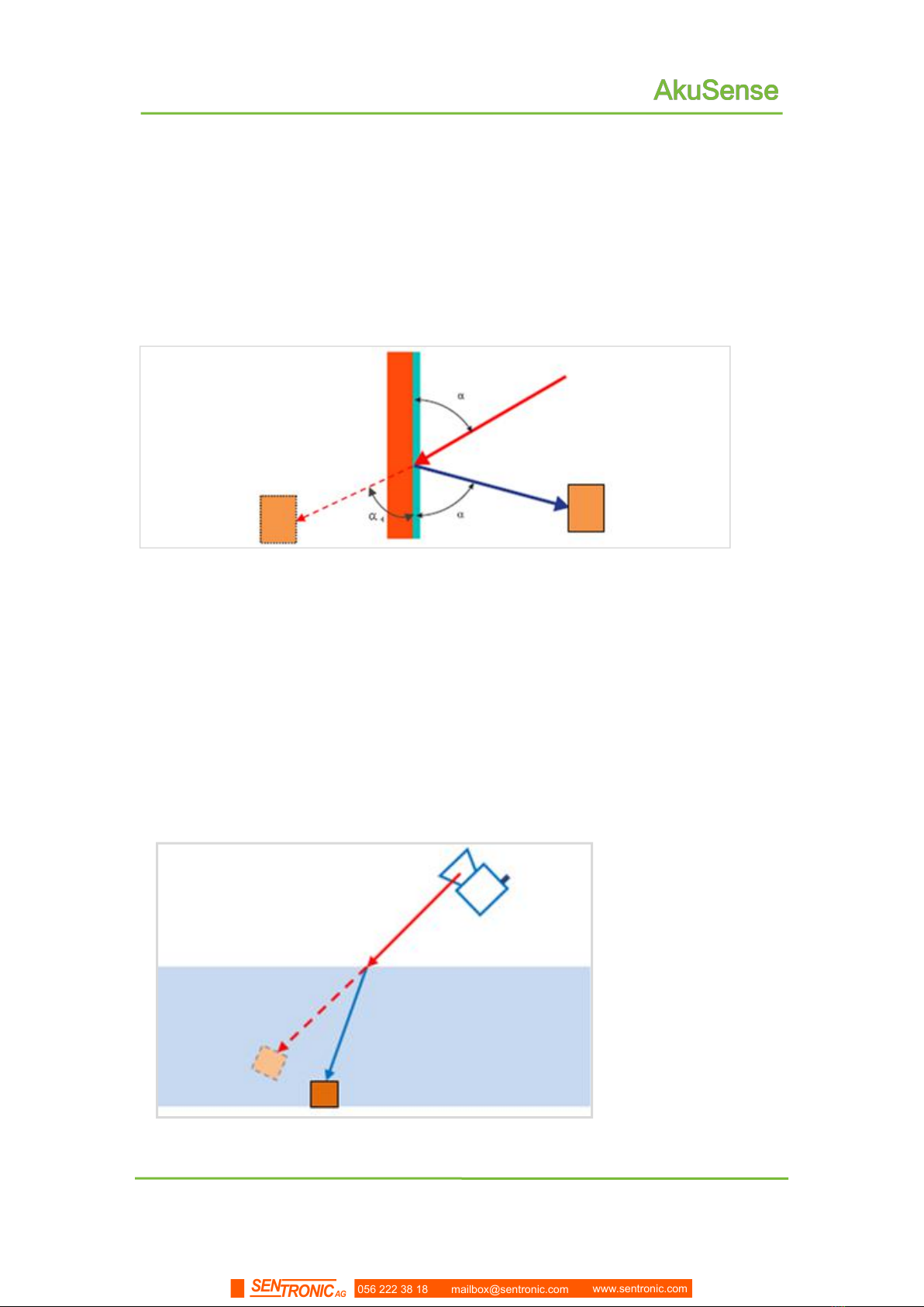
4.1.4 Mirror target
When measuring a mirror target, it can only be effectively measured when the target
surface is perpendicular to the incident laser. If the incident angle of the laser is not
perpendicular, the actual diffuse reflectance the sensor receives will decrease, which will
makes it impossible to measure. And the actual measurement result would rather be the
shadow of the target than the target itself . See the figure 4.3.
Figure 4.3 Mirror measurement
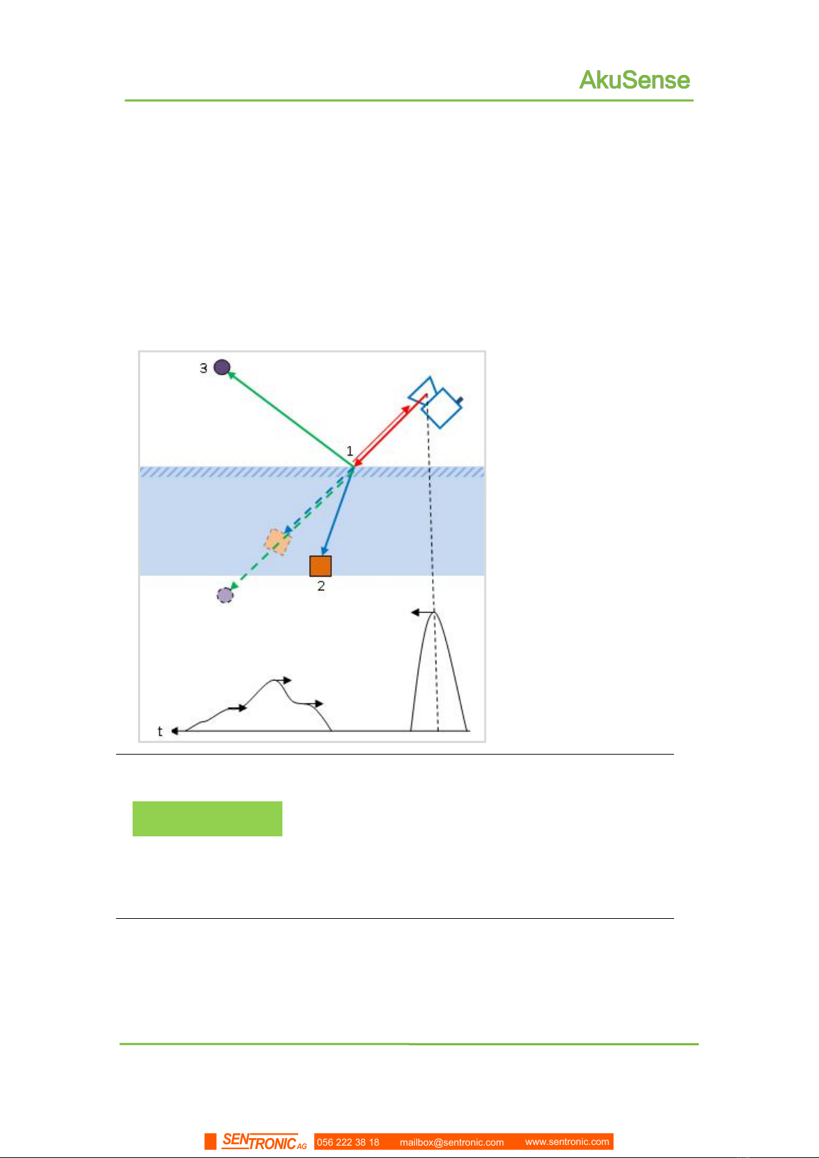
4.1.5 Transparent media
When there is a transparent medium (such as clean water) in the surrounding
environment, targets inside or behind the medium can be detected. However, because the
light will be refracted in the transparent media, the measured target position will be
deviated.
As shown in “Figure 4.4”,the target is actually located on the refracted optical path, and
the measurement result is located on the straight optical path.
Figure 4.4 Transparent medium measurement
In addition, the AS-11C may also receive two reflection echoes, one from the actual
056 222 38 18 mailbox@sentronic.com www.sentronic.com
SENTRONIC AG
18
AS-11C User Manual
Applications
target surface reflection inside or behind the transparent medium, and the other from the
diffuse reflection on the surface of the incompletely clean transparent media. The result is
uncertain, it may be the surface of the media, or it may be the actual target.
If the surface of the transparent media is close to the mirror (such as glass), a third
reflected echo may be generated because the measuring laser pulse emitted by the
AS-11C will reflect and hit other targets on the reflected optical path. All these echoes may
form a complex overlapping relationship based on the length of actual optical path,
resulting in uncertain measurement results
Figure 4.5 Mirror transparent media measurement
Main Point
In actual use, special treatment is required for
transparent media in the environment, especially those
with surfaces close to the mirror, to avoid unstable or
erroneous measurement results. The methods can be
lowering the transparency and reflection ability of the
surface of the media, or shield these positions when
processing the measurement data.
056 222 38 18 mailbox@sentronic.com www.sentronic.com
SENTRONIC AG
26
AS-11C User Manual
Applications
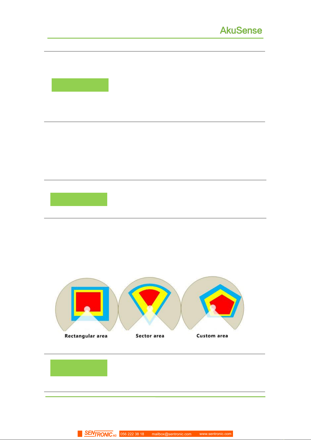
4.4.2 Regional Group and Monitoring Regional Group
Annotation
The AS-11C's regional monitoring function is based on the
work of regional groups. Each regional group includes three
regions, namely, "attention zone","pre-warning zone" and
"alarm zone". They monitor the signal and output it through
TCP message and I / O output terminal. Under normal
circumstances, "attention zone" contains "pre-warning
zone", and "pre-warning zone" contains "alarm zone", as
shown in "Figure 4.7 Regional Group".
In the area group shown in "Figure 4.7", the rectangular regional group and the sector
Regional Group are the regional groups of the built-in shape of the system. Users can use
FILPS to adjust their shape parameters and fine-tune the edges to get the their Area
group; the custom regional group is a polygon group drawn manually by the user using the
custom regional group function of FILPS, and the edge can be fine-tuned after drawing.
Related Reading
For the editing and drawing methods of the regional group,
please read Section 8.5 "Editing the shape of the regional
group" in the "Lidar Diagnostic and Configuration Software
(FILPS) User Manual".
AS-11C built in 4 preset regional groups with different shapes, different sizes and
different positions, as shown in Figure 4.2 and 4.3. In actual use, you can choose
from these 4 groups as needed, use FILPS's editing function to edit and modify, or create
a new regional group.
Figure 4.7 Regional Group
Attention
After binding a monitoring mode to each regional group, a
monitoring regional group is formed, which can be activated
and put into operation.The AS-11C can have up to 16
concurrently monitoring regional groups.
056 222 38 18 mailbox@sentronic.com www.sentronic.com
SENTRONIC AG
27
AS-11C User Manual
Applications
Software Operation
You can use the FILPS to activate the AS-11C monitoring
regional group. For usage, please read "Lidar Diagnostic
and Configuration Software (FILPS) User Manual" Section
8.6 "Regional Monitoring Function Operation Configuration"
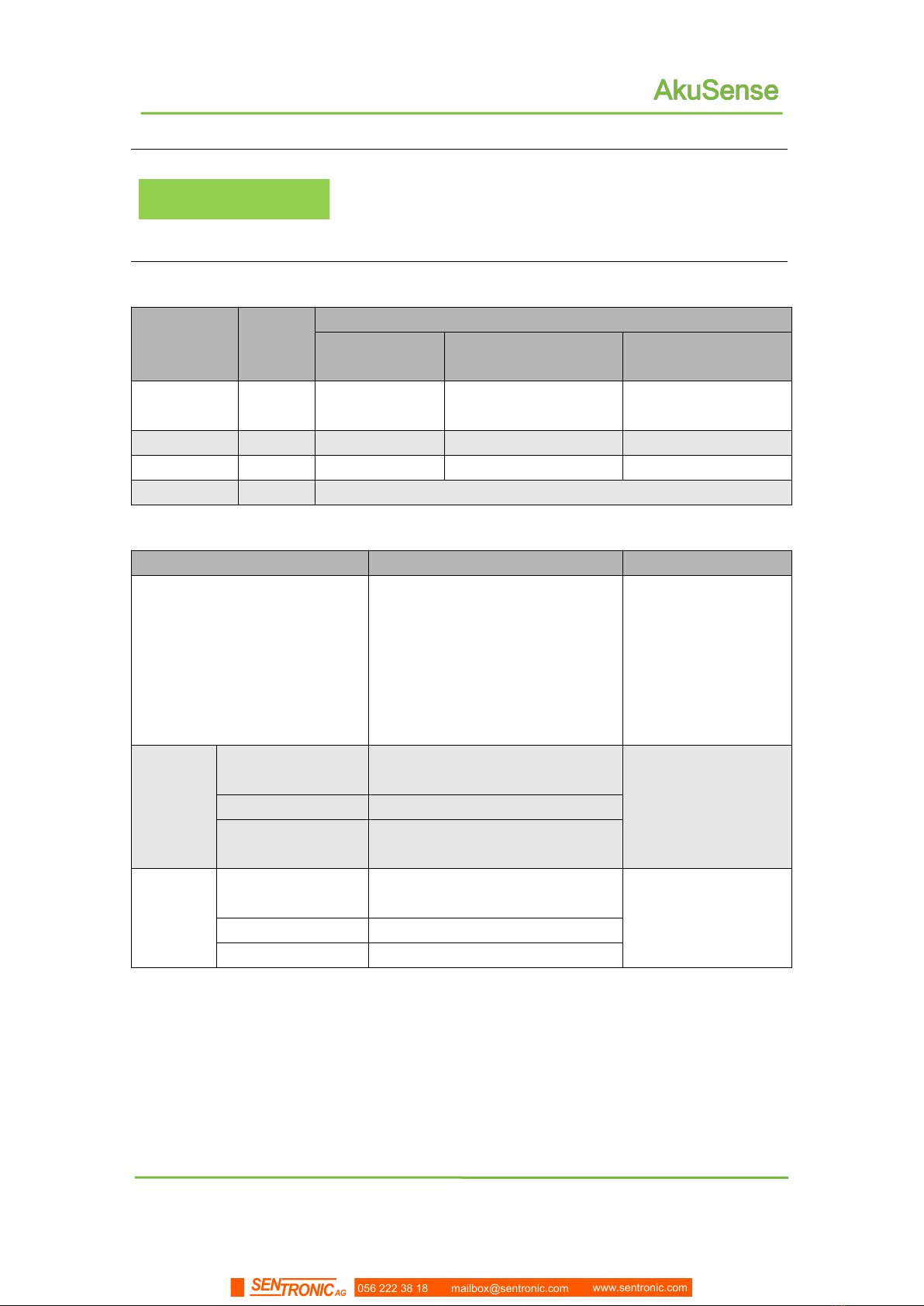
Table 4.2 Preset area group
Regional
Group
Shape
Parameter of the shape of Warning zone
Center position
Length,width/Radius of
Warning Zone
Angle range
1
Rectang
ular
(0, 50)
100cm╳100cm
2
Sector
100cm
[0°, 180°]
3
Round
100cm
4
Polygon
pentagon
Table 4.3 Basic parameters of preset area groups
Parameter
Setting Value
Description
Radius of the shielding zone
20cm
The minimum radius
of the shielding zone
at short distance.
Targets smaller than
this distance will not
generate monitoring
signals.
Buffer
distance
of the
warning
area
Rectangular (0 #)
50cm (upper) / 0 (lower) / 20cm
(left) / 20cm (right)
The buffer distance
from the edge of the
warning area to the
edge of the alarm
area.
Sector(1#)
50cm
Round(3#)
50cm
Attention
zone
buffer
distance
Rectangular (0 #)
100cm (upper) / 0 (lower) / 40cm
(left) / 40cm (right)
The buffer distance
from the edge of the
attention zone to the
alarm zone.
Sector(1#)
100cm
Round(3#)
100cm
056 222 38 18 mailbox@sentronic.com www.sentronic.com
SENTRONIC AG
31
AS-11C User Manual
Applications
4.4.5 Monitoring Mode
The AS-11C built-in three monitoring modes. Below are the details.
Table 4.4 Monitoring mode and parameters
Monitoring
mode
Function description
Monito
ring
signal
Parameter description
Parameter
Unit
Default
value
Point
monitoring
Count the number of target points
entering the region. If the number of
target points exceeds the set
number threshold and the existence
time exceeds the set response time
threshold, the monitoring signal is
output.
Attenti
on
pre-wa
rning
alarm
Number of
points
Point/
points
6
Duration
Scan
ning
cycle
0
Target
width
monitoring
The target entering the area is
detected, and if there is a target
whose width exceeds the set width
threshold, and the time exceeds the
set response threshold, a monitoring
signal is output.
Attenti
on
pre-wa
rning
alarm
Target’s
width
cm
6
Existence
time
Scan
ning
cycle
0
Contour
monitoring
Check the integrity and stability of
the background contours obtained
by self-learning in the monitoring
area group. If the background
contour changes beyond the set
change distance threshold, the total
change length exceeds the set
change length threshold, and the
duration exceeds the set response
threshold, an alarm signal is output.
alarm
Change
distance
cm
20
Change
length
cm
6
Duration
Scan
ning
cycle
0
In the factory setting of AS-11C, the preset monitoring
mode of each area group is "target width monitoring".
Related Reading
For the selection of monitoring mode and parameter
adjustment method, please read Section 8.6 “Operation
Configuration of Area Monitoring Function” of “Lidar
Diagnostic and Configuration Software (FILPS) User
Manual”.
056 222 38 18 mailbox@sentronic.com www.sentronic.com
SENTRONIC AG

32
AS-11C User Manual
Applications
4.4.6 Normal target self-learning and exclusion (customized function)
If the monitoring mode of a monitoring area group is "target width monitoring",for normal
targets of a specific shape that appear at specific locations in the "attention" monitoring
area, you can enable the "normal target self-learning" function of the area monitoring
function. Normal targets are excluded to avoid unnecessary monitoring and control
actions.
Annotations
"Normal target self-learning": the current scene is
measured for a period of time, the normal target that
enters the monitoring area at a specific position and
specific shape is detected, and the normal target
contour database is generated based on the
accumulated normal target contour measurement data,
as shown in "Figure 4.9 Normal target self-learning "
Normal target exclusion": After the "normal target
self-learning" ends, whenever an intrusion target is
detected in the monitoring area, the location and
contour of the intrusion target are compared with the
normal target database. No monitoring signal is
generated;
All activated monitoring area groups can enable the
"normal target self-learning" and "normal target
exclusion" functions.
Figure 4.9 Normal target self-learning
Normal target
Normal target contour database
056 222 38 18 mailbox@sentronic.com www.sentronic.com
SENTRONIC AG

37
AS-11C User Manual
Applications
4.5.2 I/O output terminal function definition
The preset function of the I / O output terminal is defined as the device ready signal
and the area monitoring signal output, as shown in "Table 4.7 Output terminal preset
function definition".
Table 4.7 Output terminal preset function definition
OUT1
OUT2
OUT3
OUT4
Signal
Device Ready
Alarm
Pre-warning
Attention
Effective output status
(Default setting)
Connect(high
level)1
Connect(hi
gh level)
Connect(high
level)
Connect(high
level)
Effective output status
(Default setting)
-
2 s
2 s
2 s
1. The effective output state of the device ready signal is fixed to on (high level) and
cannot be changed;
2. The meaning is: when the signal becomes valid, the minimum duration of the output
state of the OUT port. During this period, the output state of the OUT port remains
unchanged even if the signal becomes invalid.
Main Point
After the device is ready, you can read the status of
the I / O terminal through TCP messages, or control the
output status of the OUT port;
The effective output status and holding time of the
area monitoring signal of the OUT port can be set
separately using the FILPS software. For the setting
method, please read Chapter 10 "Advanced
Configuration" of the "Lidar Diagnostic and
Configuration Software (FILPS) User Manual"
If you do not need to output the device ready
signal or area monitoring signal through the OUT port,
you can use the FILPS software to cancel the
association between the signal and the corresponding
OUT port. At this time, the output state of the OUT port is
no longer affected by the signal state. Chapter 10
"Advanced Configuration" of Radar Diagnostics and
Configuration Software (FILPS) User Manual.
4.5.3 I/O interface network message
The I/O terminal can be read and set via TCP message. The message type codes are:
Read I / O terminal status: LIM_CODE_IOREAD
056 222 38 18 mailbox@sentronic.com www.sentronic.com
SENTRONIC AG
50
Device installation
AS-11C User Manual
5.2 Installation height and pitching angle
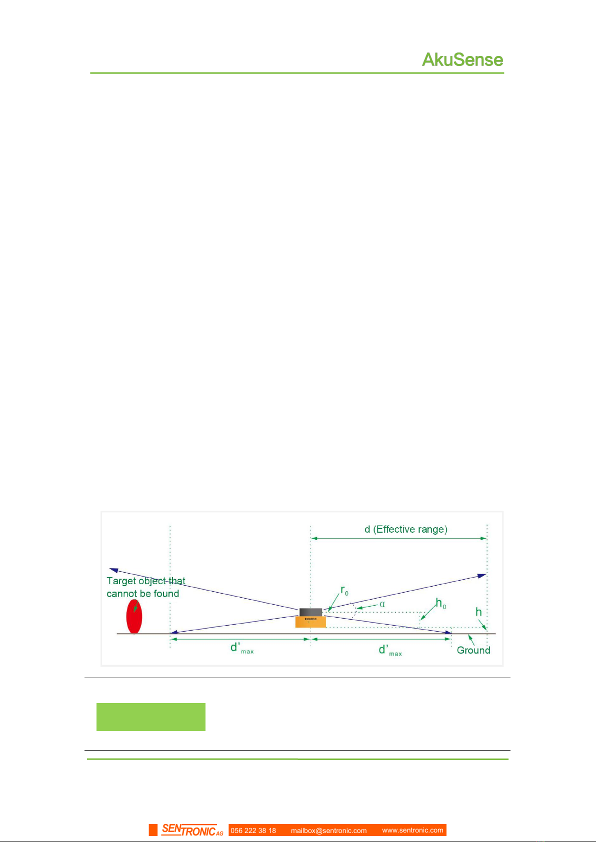
5.2.1 Relationship between installation height and effective working distance
The ranging laser light spot emitted by the AS-11C is rectangular, and the divergence
angle in the vertical direction is different from the horizontal divergence angle. The
divergence angle in the horizontal direction is 10mrad, and the divergence angle in the
vertical direction is 2mrad, with the increase of the detection distance, the light spot
increases gradually, and its lower edge extends downward gradually. If the ground is hit or
the installation surface is installed, a further target cannot be detected. Therefore, there is
a certain relationship between the effective working distance of the AS-11C and the
installation height, as shown in "Figure 5.1 the relationship between the effective working
distance and the installation height”.
Taking the horizontal floor installation as an example, the relationship between the
bottom installation height h of the AS-21C and the effective working distance d' max is:
d'max = 2(h+h0-r0) / αV
h0is The height of the light-emitting optical axis of the AS-11C relative to the bottom
surface,h0= 0.047m;
r0is diameter of light spot outlet,r0= 0.01m;
αVis vertical divergence angle of light spot,αV= 0.002。
Figure 5.1 relationship between effective working distance and installation height
Important Tips
Important Tips
The actual installation height of the AS-11C should be
determined according to the requirements of the relative
height and working range between the ground of the work
site or the base working face and the installation position.
056 222 38 18 mailbox@sentronic.com www.sentronic.com
SENTRONIC AG
51
Device installation
AS-11C User Manual
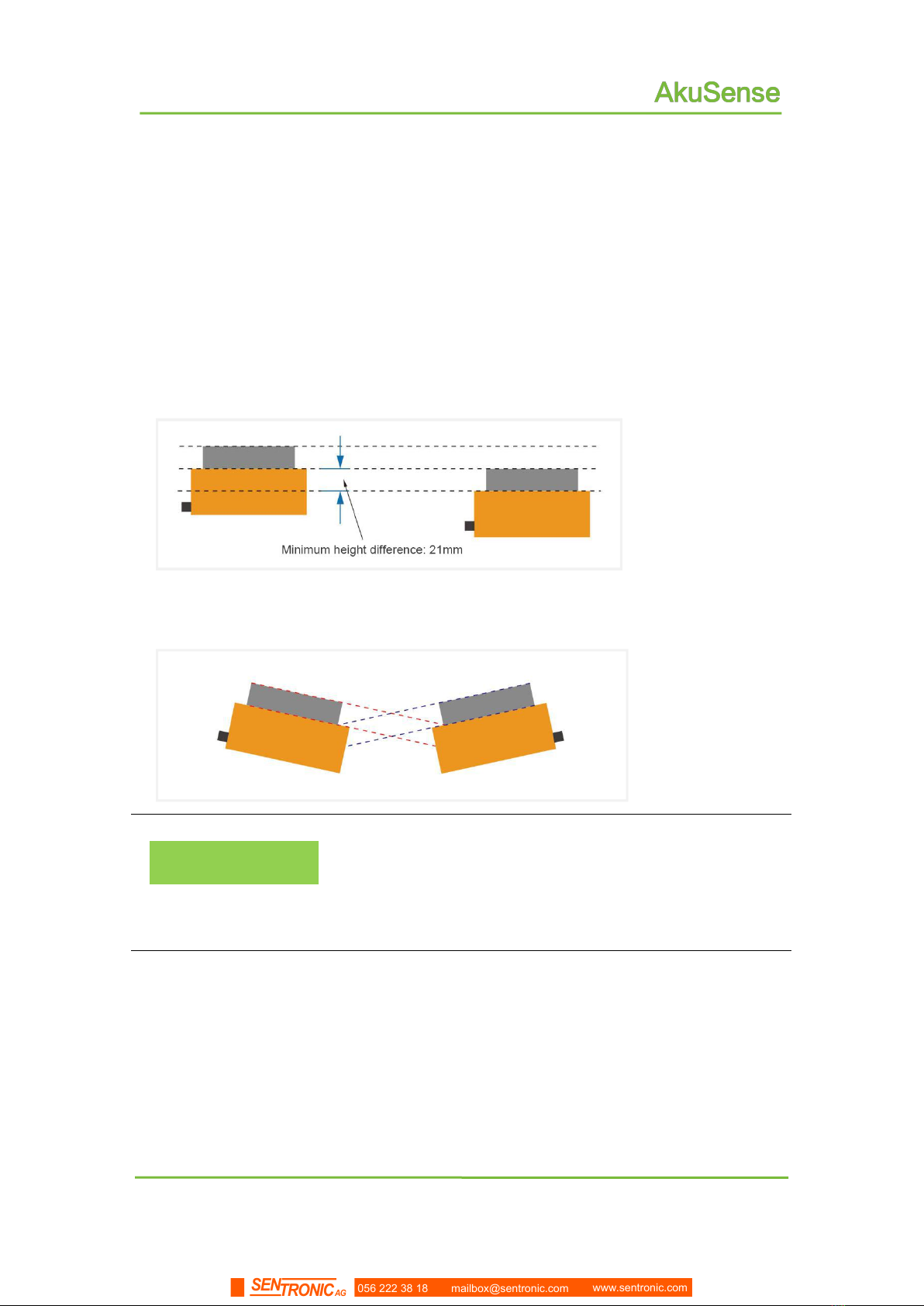
5.2.2 Height and angle adjustment when multiple LiDARs work simultaneously
If there are multiple laser lidar working at the same time in the use environment, the
laser emitted by one laser lidar should be prevented from being directly incident into the
light-transmitting cover of another laser lidar, otherwise, the measurement of the two
laser lidars may be interfered with each other, and false measurement data may appear
at their respective specific scanning angles.If there is such a possibility, the laser scanning
surface height or pitch angle of the lidar should be adjusted to avoid mutual interference,
as shown in "Figure 5.2 Scanning surface height adjustment" and "Figure 5.3 Scanning
surface pitch angle adjustment".
Figure 5.2 height adjustment of scanning surface
Figure 5.3 Pitching angle adjustment of scanning surface
Important Tips
If the above installation and adjustment cannot be
achieved, you can try to power off and re-energize the lidar
that caused the erroneous measurement until the erroneous
measurement data disappears. Once the erroneous
measurement disappears, it will not reappear in a short time.
056 222 38 18 mailbox@sentronic.com www.sentronic.com
SENTRONIC AG
Table of contents
Other SENTRONIC Accessories manuals

Popular Accessories manuals by other brands

HBM
HBM SB01A Mounting instructions

CSS MicroSystems
CSS MicroSystems AssistX AS one Instructions for use

Colzer
Colzer CZB30SS1 instruction manual

Oregon Scientific
Oregon Scientific WS909 user manual

Vinotemp
Vinotemp WINE-MATE WM-2500SSV Installation, operation & care manual

Hella
Hella CLEO 7030 Installation instructions and instructions for use

Campbell
Campbell DustVue product manual

Kampa
Kampa Fiesta AIR Pro 280 Instructions & care manual
 installation guide")
Altai Technologies
Altai Technologies A8n (ac) installation guide

Lightolier
Lightolier Lytespan MHT4RS specification

Atonometrics
Atonometrics Mars user guide

Vermont Castings
Vermont Castings Warming Shelf #0200 installation instructions


