SENTRONIC SUPERPROX SM504 Series User manual

SUPERPROX® PROXIMITY
SENSORS
Model SM504 Series
SU PE R PROX ®
Ultrasonic
Proximity
Sensors
Synchronized/
Gate-controlled
Sensing
Sensing full or empty case
conditions is greatly simplified
with these SUPERPROX®sen-
sor models. Other typical appli-
cations include sensing height
differentiation, detecting object
surfaces in specific areas, and
performing on-demand and
automation-control sensing
functions.
The SUPERPROX®Model
SM504B (cable style) and Model
SM554B (connector style) se-
ries of ultrasonic, proximity sen-
sors, when used in a set, pro-
vide for external control of the
pulsing of all the sensors. A
setup switch in these sensors,
designated “Master” and “Slave,”
selects the operating technique
• Allows sensors
to operate in close
proximity
• Detects objects at
specific points within
adjustable “window”
limits
• Makes profiling and
positioning
applications possible
• A push-button sets
window limits
• Operating range up to
2 m (79")
• CE certified
to either simultaneously synchro-
nize or gate the transmit and re-
ceive cycles of a multiple sensor
set.This unique concept is an ef-
fective solution for applications
such as: full or empty case in-
specting, on-demand controlled
sensing or inspecting, in-case
container counting, automation
control sensing, object-in-area
sensing, down container sensing,
differential height inspecting, and
more.
The synchronized technique is
designed for applications requir-
ing continuous “curtain” sensing
over a wide area. Synchronized
sensing allows any number of sen-
sors to be operating close to-
gether, thus eliminating any pos-
sible adverse ultrasonic signal in-
terference between the sensors.
Controlled or multiplexed sens-
ing of multiple objects, locations
or surfaces is accomplished us-
ing the gated technique.With this
technique, PLS and PLC output
switches or other sensing devices
may be used to trigger or gate a
sensor set. Depending on the ap-
plications, a set of these sensors
is used with an isolated switching
device to prevent possible false
sensor outputs due to changing
foreground object conditions.
Like other SUPERPROX®sen-
sors, these models have the ca-
pability to detect objects at spe-
cific points within adjustable “win-
dow” limits, thus making profiling
and positioning applications pos-
sible. A push-button sets the win-
dow limits. The sensors carry the
CE Mark and are epoxy sealed in
a tough plastic housing to resist
harsh, wet, or dirty environments
typically associated with the above
applications. The housing meets
NEMA 4X (indoor use only) and
IP67 industry standards. A Dairy
3A compliant housing is available
as an option. These sensors have
operating ranges of 51 to 635 mm
(2 to 25"), 51 to 1 m (2 to 39") and
120 mm to 2 m (4.7 to 79") and are
available in 12 to 24 VDC model
versions. 4-47
Rugghölzli 2
CH - 5453 Busslingen
Tel. +41 (0)56 222 38 18
Fax +41 (0)56 222 10 12
www.sentronic.com
Produkte, Support und Service
SEN
TRONIC
AG

Sensor Configuration
Switches
Switch 1 configures the sensor to op-
erate in either a normal or high sensitiv-
ity mode. Place this switch in the NORM
position for sensing liquid or solid mate-
rials. Place the switch in the HIGH posi-
tion for sensing soft or porous materials
that will absorb some of the ultrasonic
energy.
Switch 2 configures the sensor to op-
erate in either an object or background
sensing mode. Place this switch in the
OBJCT position to perform a sensing
function for receiving the reflected ultra-
sonic energy directly off an object. Place
this switch in the BKGRD position to
perform a break-beam sensing function
for receiving the reflected ultrasonic en-
ergy directly off a fixed background tar-
get.
Switch 3 selects the operating mode
for the sensor output to be either nor-
mally open (N.O.) or normally closed
(N.C.).
Switch 4 configures the sensor to per-
form either a slave or master operating
function. See Synchronized Sensing and
Gate-controlled Sensing descriptions for
selecting the proper switch position.
Control Compartment
A unique feature available to the user
of these sensors is the ability to quickly
set up each sensor for a specific appli-
cation.The sensor is configured through
four slide switches and a push-button
Synchronized Sensing
Synchronized sensing is a unique fea-
ture of this sensor that enables reliable
“curtain” sensing or inspecting over a
wide area by using multiple sensors in
a set. Synchronized sensing allows
these sensors to be operated close to-
gether, thus eliminating any possible
adverse ultrasonic signal interference
between the sensors.
Any number of these sensors can be
operated together to perform a synchro-
nized sensing function. It is accom-
plished by simply connecting together
the external control wire lead from all
the sensors in the set as shown in the
illustration on the next page. One of the
connected sensors must operate with
setup Switch 4 in the “Master” position
and the other connected sensors must
operate with setup Switch 4 in the
“Slave” position.The designated “Mas-
ter” sensor continuously synchronizes
the transmit and receive cycles of all
the connected sensors as a result of
this configuration.
Figure 1
1234
NORM
OBJCT
N.O.
SLAVE
HIGH
BKGRD
N.C.
MASTER
LIMITS
Model Reference Guide - SM504 Series
Use the guide below to ensure the correct model number is specified for the
application. Please note that not all sensor model combinations are available.
EXAMPLE MODEL: SM5 5 4 B - 4 00 - AF
SUPERPROX®Product Series
Power/ConnectionType (DC only)
0...12 to 24 VDC / cable style
5...12 to 24 VDC / connector style
Sensing Function
4...Proximity - Synchronized/Gate-controlled
Design Level
A…Applies to discontinued models with NPN sinking output only
B…Applies to models with NPN sinking and PNP sourcing outputs
Sensing Range
0...51 to 635 mm (2 to 25")
1...51 to 1 m (2 to 39")
4...120 mm to 2 m (4.7 to 79")
Functionality
00...Standard Proximity
05...Default Window: ±0.5"
44...Default Window: ±0.1"
67...Switch selectable, 1 or 2 echo hit recognition with high gain
Special Features
...No letter indicates standard sensor with no special features
FS...Fluorosilicone transducer face
AA...Remote limit setup (Available on DC cable models only.)
AB...RS232, 4-digit/2-decimal place output (Available on cable models only.)
AD...Limits push-button disabled
AE...RS232, 5-digit/3-decimal place output (Available on cable models only.)
AF...No LEDs
HousingTypes
...No letter indicates standard ULTEM®* plastic housing
N...NORYL®* Dairy 3A gray plastic housing
RemoteType
...No letter indicates standard couopler
R...Right-angle sensing head with armor cable
S...Straight sensing head with armor cable
Remote Cable Length
...No number indicates standard coupler
1...254 mm (10")
2...508 mm (20") 5P...1270 mm (50")
3...762 mm (30") 6P...1524 mm (60")
4...1016 mm (40")
* ULTEM®and NORYL®are registered trademarks of The General Electric Company.
4-48
Available in PVC cable only
Armored (standard) or
PVC cable (specify P
after number)
(See Figure 1) located inside a wa-
ter-tight control compartment on the
sensor.To access the controls, remove
the small square cover on the back of
the sensor. Simply loosen the two flat-
head cover screws and insert a small-
blade screwdriver in either the top or
bottom slot to remove the cover. A short
plastic tether prevents separation of the
cover from the sensor. NOTE: The
switch settings may require changing
for the intended application.
Rugghölzli 2
CH - 5453 Busslingen
Tel. +41 (0)56 222 38 18
Fax +41 (0)56 222 10 12
www.sentronic.com
Produkte, Support und Service
SEN
TRONIC
AG

Sensor Limits Setup
Push-button
First, during installation make sure the
sensor face is as parallel as possible
to the surface of the material being de-
tected.
To set the limits, simply place an ob-
ject at the desired distance from the
sensor for one limit and press the
LIMITS push-button once.This sets the
first limit and switches the sensor out-
put to an inactive state during the limit
setup.While the LIMITS push-button is
depressed, the multicolored LED lo-
cated on top of the sensor, is amber.
Upon release of the push-button, the
LED flashes amber indicating that the
second limit needs to be set within 30
seconds. Place an object at the desired
position for the second limit and press
the LIMITS push-button once. Again
while the push-button is depressed, the
LED is amber. Upon release of the
push-button, the LED flashes amber
momentarily and then turns green to
indicate acceptance of both limits. If 30
seconds elapse before the second limit
is set, the limits revert back to the pre-
vious settings.
At the same time, the sensor output
switches from the inactive to the ac-
tive state, placing the sensor into the
operational mode, ready to use. When
power is off or interrupted, the limits
are retained in a nonvolatile memory.
If in setting either limit the echo from
the object is too weak or distorted, the
LED flashes RED for 10 seconds (or
until the button is pressed again) indi-
cating the limit setting was not accepted
by the sensor. Attempt to set both lim-
its again, being careful to keep the ob-
ject surface parallel to the face of the
sensor.
Minimum allowed distance between
any two setup limits is 13 mm (1/2").
The multicolored LED flashes RED af-
ter the press and release of the LIM-
ITS push-button for the second limit
setting if the distance between the limit
settings is less than 13 mm.The multi-
colored LED continues flashing RED ei-
ther until the LIMITS push-button is
pressed and released once for the first
limit setting or until 10 seconds have
elapsed. Pressing and releasing the
LIMITS push-button once reinitiates the
limit setup sequence. If 10 seconds
elapse before the LIMITS push-button
is pressed and released for the second
limit setup, the limits revert back to the
previous settings.
A special feature provides an auto-
matic 13 mm (1/2") window limits setup
function. Simply place an object within
the sensing range of the sensor and
press the LIMITS push-button twice in
succession without moving the object.
A limit is set on a line 1/4" in front and
back of the object surface nearest the
sensor.
Multicolored LED Indicator
During Limit Setup
Prior to pressing LIMITS push-
button:
• Off - Sensing no object or
object is outside of the
sensing range
• Red - Sensing an object out
side the set limits
• Green - Sensing an object
inside the set limits
LIMITS push-button depressed for
first time:
• Amber - sensing a good object
surface condition
• Red - Sensing no object or a
poor object surface condition
LIMITS push-button released for
first time:
• Flashing Amber - First limit
accepted,waiting for second
limit
• Flashing Red - First limit not
accepted; retry setting limit
LIMITS push-button depressed for
second time:
• Amber - Sensing a good
object surface condition
• Red - Sensing no object or a
poor object surface condition
LIMITS push-button released for
second time:
• Green or Red - Second limit
accepted
• Green or Amber - Second
limit accepted
• Flashing Red - Second limit
not accepted; retry setting
both limits
Multicolored LED Indicator
in Operational Mode
• Off - Sensing no object or
object is outside the sensing
range
• Red -
Sensing as object
outside the set limits
• Green -
Sensing an object
inside the set limits
Red LED Indicator in
Operational Mode
The red LED serves as a visual
indicator for the sensor output. The
LED is illuminated when the output
is in an active (ON) state. Note:
Indicator is not provided on all
models.
Electrical Wiring
Sensor wires must be run in
conduit free of any AC power or
control wires.
4-49
View of Plug on Connector Style
Sensor
BLACK1
NPN
ORANGE
3
Sync/Gate
WHITE 5
PNP
BLUE 2
Common
BROWN 4
+ 12 to 24 VDC
Gate-controlled Sensing
Gate-controlled sensing is another
unique feature that enables this sensor
to perform periodic sensing of multiple
objects or locations. Depending on the
application, one or a set of these sen-
sors is used with an isolated switching
device for preventing possible false
sensor outputs due to changing fore-
ground object conditions. Devices such
as SUPERPROX®sensors, program-
mable limit switches or other proximity
sensor switches with an open-collec-
tor, current sinking output are typically
used to perform the isolated gate-switch
or “Master” sensor function.
Gate-controlled sensing is accom-
plished by connecting the external con-
trol wire lead from each sensor to the
DC supply voltage common through the
isolated switch as shown in the illus-
tration on the next page. Each con-
nected sensor must operate with setup
Switch 4 in the “Slave” position. In this
configuration, the sensors simulta-
neously transmit and receive ultrasonic
energy only when the gate device is
switched to the ON or CLOSED state.
When the gate device is switched back
to the OFF or OPEN state, the sensor
outputs are latched from changing state
until the next gate-switch cycle.
SUPERPROX® PROXIMITY
SENSORS
Sensor Wire colors
Cable Connector
Style Style
(+)12 to 24 VDC RED BROWN
NPN/Sinking Output WHITE BLACK
PNP/Sourcing Output BROWN WHITE
Sync/Gate Control GREEN ORANGE
DC Common BLACK BLUE
Rugghölzli 2
CH - 5453 Busslingen
Tel. +41 (0)56 222 38 18
Fax +41 (0)56 222 10 12
www.sentronic.com
Produkte, Support und Service
SEN
TRONIC
AG
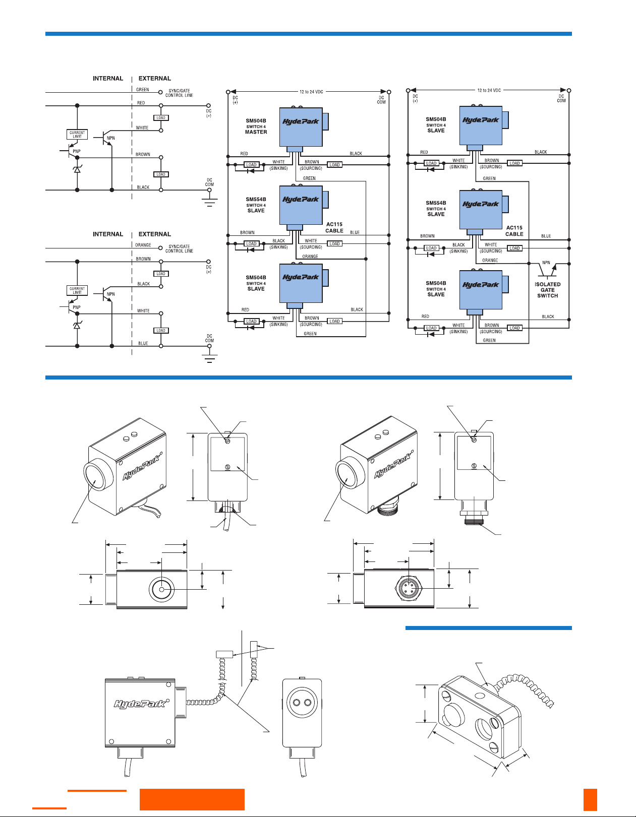
Synchronized Sensing
Connections
#4 stainless steel screw
(SEM retained) 2x
Pry notch
(2-PL)
Access door to control
compartment w/ gasket
& retaining cable
1/2" NPT pipe thds.
for conduit mtg.
Sealed cable
3 meters long
(10 ft)
Sensing face
78 mm
(3.06)
44 mm
(1.75)
22 mm
(.87)
92 mm (3.63)
79 mm (3.13)
51 mm
(2.00)
35 mm DIA
(1.37)
#4 stainless steel screw
(SEM retained) 2x
Pry notch
(2-PL)
Access door to control
compartment w/ gasket
& retaining cable
7/8"-16 UNF
threads
Sensing face
106 mm
(4.17)
44 mm
(1.75)
22 mm
(.87)
92 mm (3.63)
79 mm (3.13)
51 mm
(2.00)
35 mm DIA
(1.37)
Stainless steel
sensing probe
25 mm (1.0") long x
13 mm (1/2") diameter
Straight
style
Right angle
style
Stainless steel armor cable
254 mm (10"), 500 mm (20"),
762 mm (30"), 1016 mm (40")
long x 5 mm (3/16") diameter
Note: Illustrated models may not be the exact
representation for these sensors due to possible
design modifications.
REMOTE HEAD
REF.
51.0 mm
(2.000)
28.5 mm
(1.120)
16.0 mm
(.630)
AC230
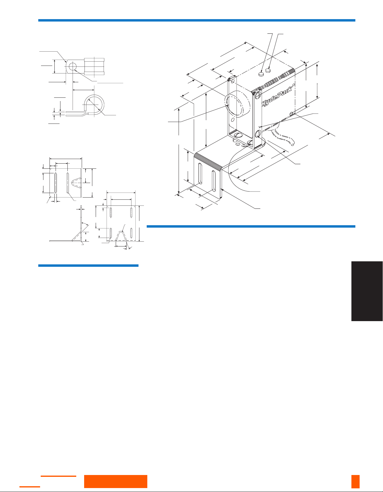
Mounting Accessories
Dimensions
Cable Model Connector Model
Remote Sensing Models
Cable Model
Connector Model
Outputs
4-50
Gate-controlled Sensing
Connections
Rugghölzli 2
CH - 5453 Busslingen
Tel. +41 (0)56 222 38 18
Fax +41 (0)56 222 10 12
www.sentronic.com
Produkte, Support und Service
SEN
TRONIC
AG
Accessories
Model AC115, Straight, 7/8-16 mini, 5-conductor,
mating connector cable, 4 m (12'), for Model
SM554B-XXX series connector-style prox sensors
with alarms
Model AC115-50, Straight, 7/8-16 mini, 5-conductor,
mating connector cable, 15 m (50'), for Model
SM554B-XXX series connector-style prox sensors
with alarms
Model AC213, Stainless and Teflon, remote sensing
probe mounting bracket
Model AC222, Standard, stainless mounting bracket
assembly, slotted for vertical adjustment
Model AC226, Stainless and polyamide conveyor-rail
clamp/bracket set
Model AC229, Stainless, plate-style, right-angle,
mounting bracket, with base slotted for forward
reverse adjustment and side slotted for sensor
adjustment
Model AC230, Three-piece, stainless, mounting
bracket assembly with O-ring mount for sensor
models with remote heads.
See page 7-1 for accessory photos.
General Specifications
Sensing
Ranges:
51 to 1 m (2 to 39")
120 mm to 2 m (4.7 to 79")
Sonic Frequency: 200 kHz
Power Requirements
DC Models:
12 to 24 VDC ± 10% @ 80 mA, 2 W max.,
excluding output load (regulated supply)
Output/Input
DC Models:
NPN Sinking: Switch selectable N.O./N.C.
Sinking on-state voltage drop:
Maximum 0.25 volts @ 60 mA
Sinking load current:
Maximum 100 mA
Sinking output voltage:
Maximum applied 30 VDC
PNP Sourcing: Switch selectable N.O./N.C.
Sourcing output current:
Maximum 100 mA
Current limit protected to less than 160 mA
Input:
Input voltage range: 0 to 30 VDC
Vin-high, minimum: 2.5 V
Vin-low, maximum: 1.4 V
Input current maximum: 0.76 mA
ResponseTime
“On” 10 ms, “Off” 10 ms to “On” 30 ms,
“Off” 30 ms, depending upon model
Indicators
Multicolored (Amber, Red, Green) LED: Indicates
limits setup and operational modes
Red LED: Visual indicator for sensor output;
illuminated when output is in an active (On) state.
Connections
Cable Style Models:
DC: 24 AWG, PVC jacket,
5-conductor, 3 meters (10') long, standard
Connector Style Models:
DC: 5-pin “mini” style
Protection
Power Supply: current-limited over-voltage, ESD,
reverse polarity
Outputs, Input: current-limited over voltage, ESD,
over-current.
Environmental
Operating Temperature Range:
0oto 50oC (32oto 122oF)
Storage Temperature Range: -40oto 100oC
(-40oto 212oF)
Operating Humidity: 100%
Protection Ratings: NEMA 4X (indoor use only),
IP67
Chemical Resistance: Resists most acids and
bases, including most food products.
Fluorosilicone transducer face is available to
provide resistance to aromatic and petroleum-
based hydrocarbons.
Agency Approvals
CE Mark: CE conformity is declared to:
EN61010-1: 1990 including amend. No.1:1992
EN55011 Group 1 Class A, EN50082-1.
Declaration of conformity available upon request.
AC Models SM520/570 carry the ETL safety label.
Construction
Dimensions (overall)
92 mm (3.625") L x 44 mm (1.75") W
x 91 mm (3.58") H
Housing:
Case: ULTEM®* (FDA approved)
Optional: NORYL®* (USDA-Dairy 3A
Sanitary Standards compliant)
Transducer Face: Silicone rubber (FDA ap-
proved)
Optional: Fluorosilicone rubber
Sensor Cable: PVC jacket
LED: Polycarbonate
* ULTEM®and NORYL®are registered trademarks of The General
Electric Co.
Sensing face
(outline of
SUPERPROX ref.)
Multi-colored LED
sensing indicator
Red LED output
indicator
Upper mtg. bracket
stainless steel
Note: Bracket is abl
e
to be rotated
#10-32 x 57 mm (2 1/4”) lg
stainless steel screw
& ESNA nut (farside)
2-places
#10-32 x 12.7 mm (1/2”) lg
stainless steel screw
& ESNA nut
2-places
Lower support bracket
stainless steel
with two 35 mm lg x 7.1 mm wd slots
(
1.380 x .280
)
49 mm
(1.93)
25.4 mm
(1.00)
52 mm
(2.06)
147 mm
(5.78)
95 mm
(3.75)
51 mm
(2.00)
92 mm
(3.63)
79 mm
(3.13)
14.3 mm
(.56)
13 mm
(.52)
44 mm
(1.75)
78 mm
(3.06)
143 mm
(5.63)
71 mm
(2.78)
64 mm REF
(2.52)
65mm
(2.56)
91.44 mm
(3.60)
65.00 mm
(2.56) 2x
6.6 mm 2x
(.23) Wide
11.43 mm
(4.50)
72.00 mm
(2.83) 2x
30.5 mm (2x)
(1.20)
13.2 mm
(.52) 2x
R 6.35 mm
(.25)
FULL R.
TYP
31.0 mm
(1.22)
20
û
56 mm
(2.20)
R 4.8 mm
(.19)
45
û
3.17 mm
(.125) TYP
FULL R.
TYP
65.00 mm
(2.56) 2x
13.2 mm
(.52)
101.60 mm
(4.00)
45.7 mm
(1.80)
91.44 mm
(3.60)
38.0 mm
(1.50)
19.00 mm
(.75)
R 8.0 mm
(.31) 4x
7.10 mm
(.28) 2x
.204 DIA THRU
0.52 cm
R .750
1.91 cm
.750
1.91 cm
.376
0.96 cm
1.186
3.01 cm
.064
0.16 cm
.438
1.11 cm
.128
0.33 cm
AC222
Mounting Accessories
AC213
4-51
SUPERPROX® PROXIMITY
SENSORS
Rugghölzli 2
CH - 5453 Busslingen
Tel. +41 (0)56 222 38 18
Fax +41 (0)56 222 10 12
www.sentronic.com
Produkte, Support und Service
SEN
TRONIC
AG

4-52
SM504 Series
Proximity Synchronized & Gate-controlled Sens-
ing
12-24 VDC
Cable
Connector
2m(79")
1 m (39")
635mm (25")
Standard
Rt. Angle
Straight
Silicone*
Fluorosilicone*
ULTEM
®
*
NORYL
®
*
Default Window
Notes
Power Version
Connection
Style
Sensing
Range
Transducer
Style
Materials
Special
Features
Remote
Transducer Housing
Model No.
SM504B-000•�� �� ��
SM504B-000 AA �� �� �� Remote limit setup
SM504B-005 AA �� �� ��
±0.5"
Remote limit setup
SM504B-067 �� �� �� Switch selectable, 1 or 2 echo, hit recognition with high gain
SM504B-100•�� � � ��
SM504B-100 R3 � � � �
(30")
��
SM554A-067 � � �� �Switch selectable, 1 or 2 echo, hit recognition with high gain
SM554B-000•� � �� ��
SM554B-000 S4 �� � �
(40")
��
SM554B-005 � � �� ��
±0.5"
SM554B-044 � � �� ��
±0.1"
SM554B-067 � � �� �� Switch selectable, 1 or 2 echo, hit recognition with high gain
SM554B-100•���� ��
SM554B-105 ���� ��
±0.5"
SM554B-400 AF � �� � �� No LEDs
Selection Chart
• = Most commonly stocked sensors
* = See definition in
Sensing Terms
.
All possible sensor configurations are not listed here.
Rugghölzli 2
CH - 5453 Busslingen
Tel. +41 (0)56 222 38 18
Fax +41 (0)56 222 10 12
www.sentronic.com
Produkte, Support und Service
SEN
TRONIC
AG
Table of contents
Other SENTRONIC Accessories manuals

Popular Accessories manuals by other brands

Stahl
Stahl 8579/61 Series operating instructions

Schmalz
Schmalz FS-5-D-2NA-K Assembly instructions

Monoprice
Monoprice 7933 instruction manual

Centrica
Centrica PAN-42 Operation and maintenance manual

Cooper Lighting
Cooper Lighting HALO Home HIWMSB1BLE40AWH installation instructions

CS Instruments
CS Instruments VA 521 instruction manual


