SENZIME TetraGraph SEN 2001 User manual

SEN 008
Issue 9.3
23 May 2019
TetraGraph
Neuromuscular Transmission Monitor
Operating Instructions
TetraGraph Model SEN 2001

SEN 008
Issue 9.3
23 May 2019
Contents
1. Introduction .......................................................................................................................... 1
2. Warnings and Cautions......................................................................................................... 1
3. Scope of Use and Contraindications ..................................................................................... 1
4. Intended Users...................................................................................................................... 2
5. Modes of Operation.............................................................................................................. 2
6. Train of Four (TOF), TOF Ratio (TOFR) and TOF Count (TOFC).............................................. 3
7. Post Tetanic Count (PTC) ...................................................................................................... 4
8. Single Twitch (ST) .................................................................................................................. 4
9. Associated Devices and Accessories ..................................................................................... 4
10. Summary of Warnings, Cautions and Side-Effects................................................................ 5
11. Symbols and Icons................................................................................................................. 6
12. Getting Started...................................................................................................................... 8
13. Setting Up ............................................................................................................................. 9
14. TetraSens Electrodes ............................................................................................................ 9
15. Operation.............................................................................................................................. 11
16. Troubleshooting.................................................................................................................... 22
17. Maintenance and Battery Charging ...................................................................................... 24
18. Cleaning and Disinfecting...................................................................................................... 25
19. Performance and Technical Specifications ........................................................................... 26
20. Environment ......................................................................................................................... 27
21. Electromagnetic Compatibility Information ......................................................................... 28
22. Product Warranty ................................................................................................................. 28
23. Disposal of Waste Electrical and Electronic Equipment ....................................................... 29

SEN 008
Issue 9.3
23 May 2019 Page 1of 29
1. Introduction
These instructions are intended to assist with the operation of the TetraGraph
Neuromuscular Transmission (NMT) monitor and its TetraSens electrodes.
It is important that these instructions be read thoroughly and understood before
using the equipment.
An NMT monitor such as the TetraGraph is intended to supplement clinical
information obtained with other monitors, such as peripheral oxygen saturation
(SpO2), end-tidal carbon dioxide (ETCO2), as well as clinical assessment, to determine
the adequacy of ventilation.
Always check the TetraGraph monitor and ensure it is able to complete the self-
check sequence when first turned on. Inspect the device and associated accessories
for any physical damage or missing parts.
2. Warnings and Cautions
The European Medical Device Directive requires all manufacturers to include
appropriate warnings and cautions for their equipment and many of the warnings
and cautions shown here also apply to similar devices.
To make sure that all users are well informed, various warnings and cautions are
made throughout these instructions.
A WARNING is given when the personal safety of the patient or user may be affected and when
disregarding this information could result in injury.
A CAUTION is given when special instructions must be followed. Disregarding this information could cause
damage to the device.
3. Scope of Use and Contraindications
WARNING: Not for use in MRI settings, with flammable anaesthetic, or in oxygen enriched atmospheres.
The Intended Use of the TetraGraph is to deliver stimulations to a nerve and record,
measure, analyse and report muscle electrical activity to determine muscle function.
TetraGraph is a Neuromuscular Transmission (NMT) monitor intended for use in
hospital settings including operating rooms, subsequent recovery areas and in critical

SEN 008
Issue 9.3
23 May 2019 Page 2of 29
care settings. The device is for use with patients (excluding neonates), and where
the patient is mechanically ventilated and when a neuromuscular block has been
administered. The use of TetraGraph is intended to supplement clinical information
obtained with other monitors, such as peripheral oxygen saturation (SpO2), end-tidal
carbon dioxide (ETCO2), as well as clinical assessment, and these must remain the
main patient monitors to determine the adequacy of ventilation.
Neuromuscular Transmission is the transfer of an electrical impulse between a motor
nerve and its associated muscle. NMT is blocked by neuromuscular blocking agents
which cause transient muscle paralysis, preventing the patient from moving and
breathing spontaneously.
Muscle relaxation is used during general anaesthesia to enable endotracheal
intubation and to provide optimal surgical conditions. In critical care, muscle
relaxation may be used during mechanical ventilation. In these circumstances,
TetraGraph can be used as an objective monitor of neuromuscular transmission.
Patients with pre-existing neuromuscular disease (Myasthenia Gravis, Dystrophy etc.)
or patients with cerebrovascular accidents (CVAs or Stroke) may have unexpected
electromyographic responses that may affect the results of the monitoring. Place the
EMG responses in appropriate clinical context.
4. Intended Users
TetraGraph must be operated by trained and competent clinical staff and used in
accordance with approved clinical practice and local guidelines and
recommendations.
5. Modes of Operation
A Neuromuscular Transmission (NMT) monitor shows the presence of a
neuromuscular block by stimulating a peripheral motor nerve and evaluating the
evoked muscle response. TetraGraph undertakes this function by periodically
applying electrical stimulation to the peripheral nerve and directly measuring the
evoked electromyographic (EMG) response of the muscles. This provides a
quantitative and automatic measurement of muscle response to a stimulus.
TOF mode, TetraGraph’s main mode of operation, is the delivery of a sequence of
four stimuli called a Train of Four (TOF) and calculating the Train of Four Ratio (TOFR)
and TOF Count (TOFC) from the evoked EMG responses. TOF stimulation is

SEN 008
Issue 9.3
23 May 2019 Page 3of 29
commonly used in assessing depth of neuromuscular blockade and recovery during
reversal.
The four evoked response amplitudes are displayed as a sequential bar graph, along
with the calculated TOFR or TOFC. The four underlying EMG waveforms recorded by
the TetraGraph may alternatively be displayed. In both cases, the vertical axis of the
bar graph is automatically scaled to fit 5 mV multiples.
In bar graph display mode, where no EMG response can be identified by the monitor,
the position of the response will be marked by a red rectangle indicating that a
measurement was attempted but no response identified.
Other operating modes available are Post-Tetanic Count (PTC) and Single Twitch (ST).
PTC mode executes a tetanic stimulation protocol, in which a high frequency
stimulus is applied, followed by a sequence of 1 Hz stimuli. PTC mode may only be
used when the TOFC is zero.
ST Mode delivers a single stimulus and displays a single response, repeated every 10
seconds. The first measurement, commonly at the start of the procedure (before the
administration of any neuromuscular block) is stored as a baseline against which
further measurements may be compared. The sequence of responses is displayed as
a scrolling sequence of bars, with the most recent measurement being adjacent to
the baseline amplitude bar.
If the baseline requires adjustment, the baseline may be reset using the reference
button ‘Ref’, which saves the most recent ST measurement as the new baseline.
6. Train of Four (TOF), TOF Ratio (TOFR) and TOF Count
(TOFC)
The baseline Train of Four Ratio (TOFR) is determined before administration of
neuromuscular blocking agents, and after induction of general anesthesia. The
baseline Train of Four (TOF) Ratio (before administration of a neuromuscular block) is
displayed as 100%, representing a ratio of 1.0. During a partial non-depolarizing
block, the percentage decreases as the degree of block increases.
Thus, as the degree of block increases, the ratio decreases from 100%, eventually
becoming 0%. When the TOF Ratio reaches 0%, the fourth twitch in the train (T4)
disappears, and only three responses remain - a TOF Count (TOFC) of 3. Fade
continues as the depth of neuromuscular block increases, until T3 disappears, and

SEN 008
Issue 9.3
23 May 2019 Page 4of 29
the TOF Count is 2. When T2 disappears and only T1 remains, the TOF Count is 1, and
when T1 disappears, the TOF Count becomes 0.
WARNING: When depolarizing agents such as succinylcholine (suxamethonium) are used, no fade may
occur, and the TOF Ratio remains 100% until all responses disappear.
7. Post Tetanic Count (PTC)
When the Train of Four Count (TOFC) reaches 0, TetraGraph enables its Post Tetanic
Count (PTC) mode. PTC mode is only operable when the TOFC is 0.
When PTC mode is selected, TetraGraph takes a new TOF reading to check the Train
of Four Count (TOFC) equals zero. If TOFC equals 0 then PTC mode becomes
operable.
The tetanic stimulation consists of a 50 Hz tetanic stimulus with a current amplitude
of 50 mA and a pulse duration of 200 µs lasting for 5 seconds, followed 3 seconds
later by up to 20 separate single twitch stimulations at 1 Hz.
PTC is the number of responses detected following a Tetanic stimulation. The
monitor will stop the stimulating and counting when a response is no longer
detected. Thus the PTC may be a number between zero and 20, zero indicating a
deep level of neuromuscular block.
TetraGraph disables PTC mode for a further 3 minutes after delivery of the PTC
sequence. Repetition of PTC measurements faster than every 3 minutes may result
in an inaccurate measurement because of post-tetanic potentiation (amplification) of
responses.
8. Single Twitch (ST)
Single Twitch (ST) is a single stimulus used by the monitor to display the peak to peak
amplitude of the muscle response millivolts (mV). The frequency of stimulation is 0.1
Hz, corresponding to one twitch every 10 seconds. ST at a frequency of 1 Hz (one
twitch per second) is delivered as part of the PTC sequence (see above).
A high frequency of ST stimulation (one stimulus per second) will increase local blood flow and speed
delivery of neuromuscular blocking agent to the monitored muscle, falsely indicating a faster onset block
than at the laryngeal muscles. This may make tracheal intubation more difficult, therefore always monitor
with TOF rather than ST for assessment of neuromuscular block onset.
9. Associated Devices and Accessories
The associated devices and accessories for TetraGraph are the TetraCord Patient
Cable and the TetraSens Electrodes.
SEN 008
Issue 9.3
23 May 2019 Page 5of 29
Use only TetraSens Electrodes. Only TetraSens Electrodes are suitable for use with the TetraGraph.
TetraSens Electrodes are strictly single use only. Reuse will risk inaccurate measurement due the drying or
loss of hydrogel and adhesive properties. Additionally, electrode re-use may lead to bacterial transmission,
cross-contamination and superficial burns.
The rechargeable battery is charged using the AC Adapter. This Adapter is configured
for local power outlets, and connects to the TetraGraph using a USB cable.
The TetraGraph may not be connected to a patient while being charged, or while attached to an AC Power
source using the Adapter or USB Cable.
Attempting to operate the TetraGraph as a Patient Monitor while connected to AC power may result in
inaccurate recordings. The TetraGraph is intended for monitoring only while in battery operation.
The USB port is also an interface for computer data transfer, compatible with
available data review and management software.
NOTE: The TetraGraph may not be operated, nor connected to a patient to perform monitoring, whilst
connected to a computer or to AC power.
The RS-232 port is an interface for multi-parameter patient monitors that are
compatible with TetraGraph. Only IEC 60601 certified equipment can be connected
to the RS-232 connector.
10. Summary of Warnings, Cautions and Side-Effects
In common with all medical devices of this nature there are inherent risks and side
effects. Whilst every effort has been made to eliminate these risks, care should be
taken when using the device. It is important that the user familiarises himself/herself
with all of the warnings and cautions contained within this document.
WARNINGS
The TetraSens Electrodes are disposable, and are for single use only.
TetraGraph is battery operated and should not be connected to a patient while being charged.
Check that the device has adequate battery charge for the procedure before commencing (full charge with a battery in good
condition will typically last for 8 hours of continued use).
TetraGraph is not for use in MRI environment (it is not MRI compatible).
Ensure that no other equipment comes in contact with the stimulating or recording electrodes.
TetraGraph is NOT to be used in the presence of flammable anaesthetic agents or oxygen enriched atmospheres.
Do not use in pregnant patients as safety of use during pregnancy has not been established.
Neuromuscular Transmission Monitoring (NMT) is intended to supplement clinical information obtained with other monitors,
such as peripheral oxygen saturation (SpO2), end-tidal carbon dioxide (ETCO2), as well as clinical assessment, which should
remain the main patient monitors.

SEN 008
Issue 9.3
23 May 2019 Page 6of 29
Patients with an implanted electronic device such as a cardiac pacemaker must not be subjected to electrical stimulation until
specialist medical opinion has been obtained.
Patients with cerebrovascular accidents (CVAs or Stroke) may have unexpected electromyographic responses.
TetraGraph is not for use near shortwave or microwave therapy equipment as this can cause unwanted stimulation in the
electrodes and incorrect operation.
When applying the TetraSens Electrodes, make sure that the contacts of the connector do not touch other conductive parts
including any connected to earth.
To avoid micro and macro-shock keep all indwelling wires and catheters clear of stimulating electrodes.
Do not touch electrodes during stimulation, as it may affect the neuromuscular response.
If high frequency (HF) electrocautery is being conducted on an arm, place the TetraSens electrodes on the opposite arm.
HF electrocautery creates interference which can cause TetraGraph to stop updating its display; it will resume after the HF
electrocautery has ceased. This behaviour is by design so that electrocautery does not interfere with NMT measurement and
result in spurious results.
If the electrosurgical grounding fails, skin burns may occur at the site of the electrodes.
High frequency stimulation (tetanus) will lead to a 2 to 3-minute period of post-tetanic potentiation in which subsequent evoked
responses are potentiated. The TetraGraph has this 3-minute delay built in.
Hypothermia of monitored muscle will significantly affect neuromuscular transmission and give erroneous information. Best
practice is to maintain the peripheral muscle normothermic.
The use of electrodes other than TetraSens, the reuse of electrodes or poor application of electrodes may result in burns due to
the current density of the stimulation electrode.
Only apply electrodes to clean, dry skin without signs of damage such as burns, tattoos or inflammation.
The TetraGraph must not be modified as this may cause a hazard to the patient.
Only use the charger and cable provided when connecting to the TetraGraph unit.
CAUTIONS
Before use, ensure the monitor is intact and the battery is fully charged. Also visually inspect the device and the TetraCord
cable for any loose or damaged parts.
If the performance of the device changes from that specified, required or expected, take the device out of service immediately.
Maintenance work must be conducted by trained personnel following the manufacturer’s guidelines.
Do not expose the device to excessive heat.
Do not use abrasive cleaners on the display. See chapter 18 for recommended cleaning procedures.
SIDE EFFECTS
The side effects that can occur from use of TetraGraph and its TetraSens Electrodes are the following:
Allergic reaction to clinical adhesive or hydrogel.
Localised irritation if stimulation electrodes are not securely fitted or are reused.
Neurostimulation using maximal currents may induce pain in un-anaesthetised patients.
NOTE: TetraSens electrodes are for single use only.
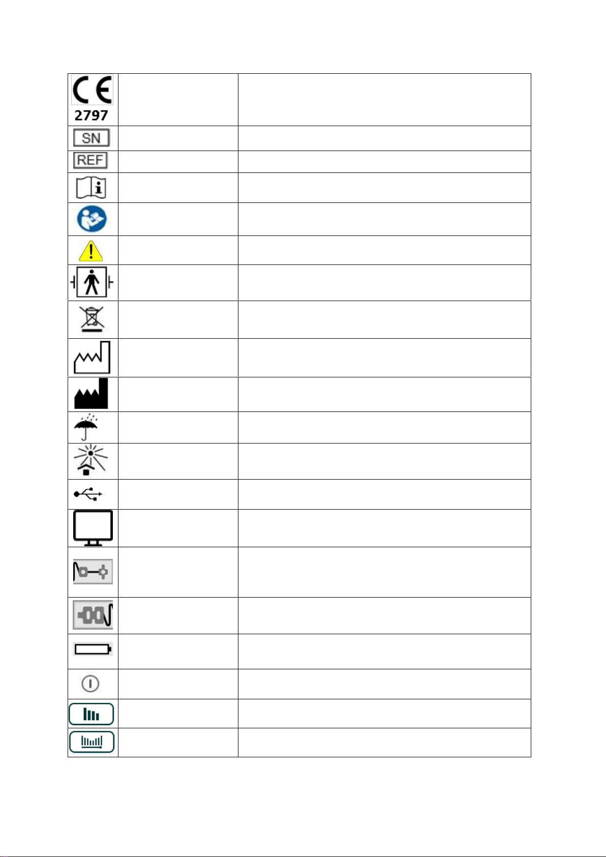
11. Symbols and Icons
The following symbols are used on the TetraGraph device and its display, and on the
TetraSens electrode.
SEN 008
Issue 9.3
23 May 2019 Page 7of 29
CE mark and notified body
number
Indicates compliance with the European Medical Device Directive 93/42 and
amendments thereto.
Symbol is associated with a number indicating the Notified Body.
Serial number
The unique serial number allocated to the device.
Reference number
The catalogue or model number of the device.
Operating instructions
The device has instructions for use.
Consult the instructions for use.
Refer to instruction manual
You must read the instructions for use.
General warning sign
Shows important information.
BF Defibrillator Applied Part
Protection against the effects of the discharge of a cardiac defibrillator is
dependent on the use of the specified cable and electrodes.
WEEE
Do not dispose of in domestic waste, see chapter 23.
Date of manufacture
Date of manufacture, shown as year and month.
Manufacturer
Name and address of the manufacturer.
Keep dry
Product should be kept dry.
Keep away from sunlight
Do not leave in direct sunlight or close to sources of excessive heat.
Universal Serial Bus (USB)
USB port for charging and downloading files.
Monitor Connection
Port for monitor cable see chapter 9.
Recording electrodes
Condition of the Evoked Response Electrodes:
Green means good connection.
Grey means no connection.
Yellow means attention required.
Stimulation electrodes
Condition of the stimulation electrodes: Green means good connection. Grey
means no connection. Yellow means attention required.
Battery condition or charging
Battery charge level on the screen.
Charging on the front panel see chapter 17.
On/Off (push–push)
To turn the device On press the button on the front panel.
To turn the device Off press the button on the screen.
Bar graph
Selects bar graph display.
Trend graph
Selects trend graph display.
SEN 008
Issue 9.3
23 May 2019 Page 8of 29
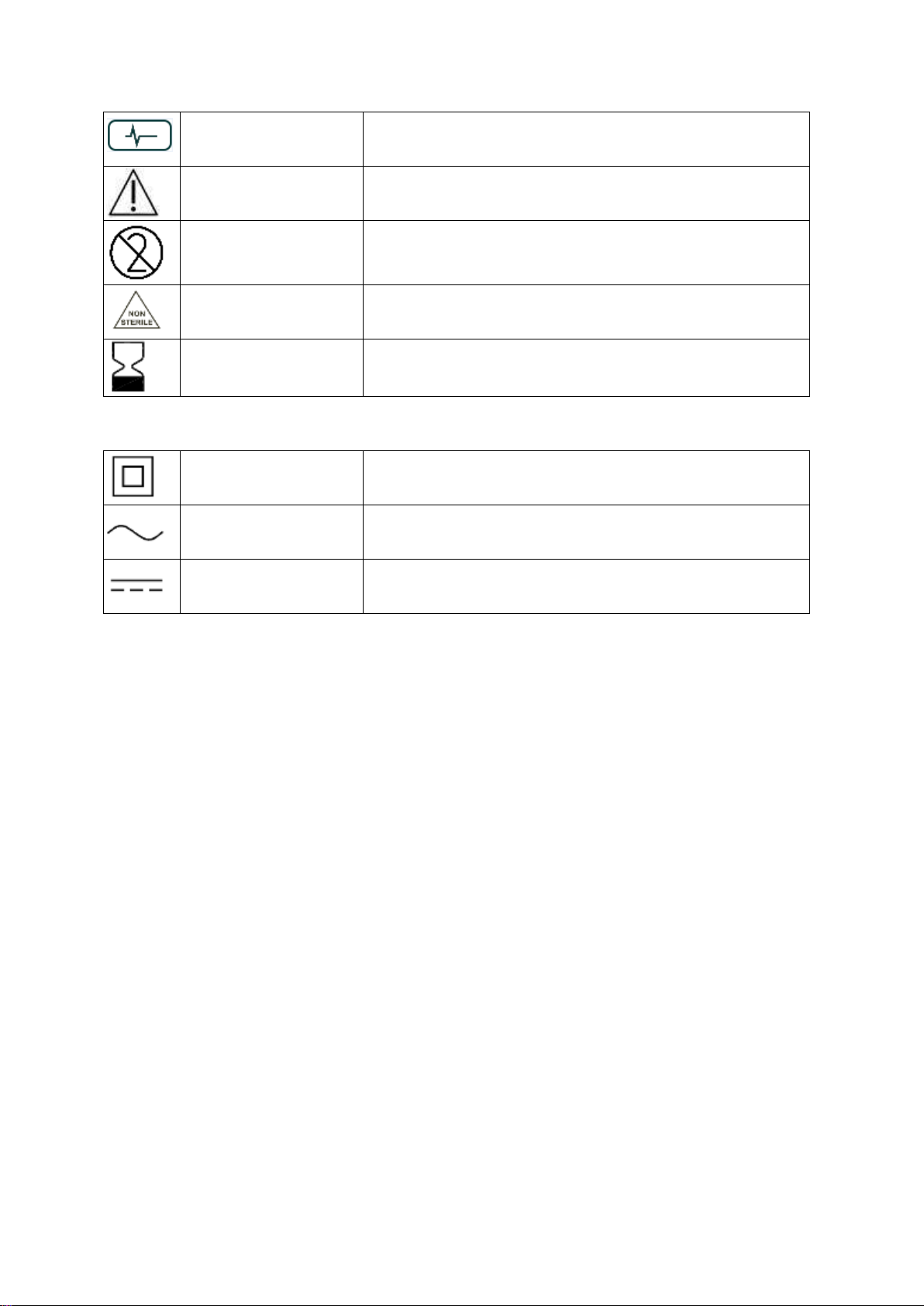
Waveform graph
Selects waveform graph display.
Caution
For the TetraSens Electrode –Caution
Do not reuse
For the TetraSens Electrode –single use only.
Non sterile
For the TetraSens Electrode.
Use by date
For the TetraSens Electrode.
The following symbols are used on the TetraGraph power supply.
IEC 60417-5172
Class II equipment.
IEC 60417-5032
Alternating current.
IEC 60417-5031
Direct current.
NOTE: There is no yellow indicator to show when the stimulation capacitors are primed as the
capacitors are continuously primed.
12. Getting Started
The system as delivered includes the following items:
SEN 2001 TetraGraph monitor
SEN 2100 TetraCord Patient Cable
SEN 2201 USB power supply adapter (FRIWO model No. FW8002MUSB/05)
SEN 2202 Battery, installed in the TetraGraph (Varta part No. 56456 702 099)
SEN 2203 USB cable (type A plug to type B plug) to connect the power supply
SEN 008 Operating Instructions (this document)
You will also require:
SEN 2002 Box of 20 TetraSens electrodes (each SEN 1002)
The user may also require:
SEN 2101 Pole Clamp for TetraGraph (Optional)

SEN 008
Issue 9.3
23 May 2019 Page 9of 29
Before use, charge the battery until the battery indicator glows green. Further
instructions are in chapter 17.
On receipt and after periods of storage, clean and disinfect the TetraGraph before
using it. Further instructions are detailed in chapter 18.
13. Setting Up
Do the following:
Make sure that the cable from the
charger is disconnected from the
TetraGraph.
Turn the TetraGraph on by pressing
the switch on the front panel.
The screen illuminates, and the monitor
performs a brief self-test.
The blue bar fills from left to right and the
display progresses to the next screen.
14. TetraSens Electrodes
Before the electrodes are placed on the skin, make sure the skin surface is clean and
dry.
WARNING Do not connect the electrodes to the monitor before placing them on the patient’s skin
Place the electrodes on the hand before connecting the electrodes to the TetraGraph
monitor using the cable provided.
The electrodes can be applied to either hand, with the stimulation electrodes over
the ulnar nerve at the wrist and the evoked response recorded from either the
hypothenar muscle below the little finger (abductor digiti minimi muscle) or, more
commonly, from the thenar muscle below the thumb (adductor pollicis muscle) as
illustrated below.

SEN 008
Issue 9.3
23 May 2019 Page 10 of 29
To attach the electrodes, do the following:
Clip to remove hair if necessary, and lightly abrade with a clean gauze sponge.
DO NOT SHAVE THE SKIN APPLICATION AREA.
Tear the pouch open along the dotted line (do not use scissors) and remove
the TetraSens Electrodes from the pouch.
Remove the stimulation (proximal, square) electrodes from the liner by lifting
the edge of the electrodes and then apply them over the ulnar nerve (nervus
ulnaris) as illustrated above.
Remove the recording (distal, round) electrodes from the liner by lifting the
edge of the electrodes and then apply them as illustrated to either the 5th
finger or the thumb.
Connect the TetraCord cable to the electrodes by squeezing the tabs on the
side of the cable connector and fully inserting the blue portion of the
TetraSens electrode connector into the cable connector, ensuring the correct
orientation as illustrated; then, release the tabs.
Electrodes must be discarded if they no longer stick firmly to the skin.
Connect the TetraCord cable to the TetraGraph monitor as shown in the
illustration on the front cover of this manual.
As illustrated above, secure the cable connector to the forearm with tape and
also secure the cable to the arm if appropriate to reduce stress on the
connection as a result of movement.
SEN 008
Issue 9.3
23 May 2019 Page 11 of 29
To remove the electrodes, do the following:
Turn the TetraGraph monitor off.
Disconnect the TetraCord cable from the TetraSens electrodes by squeezing
the tabs on the side of the cable connector.
Remove the electrode from the skin by gently peeling from the edge.
Remove possible gel residue from the skin.
Dispose of used electrodes as clinical waste.
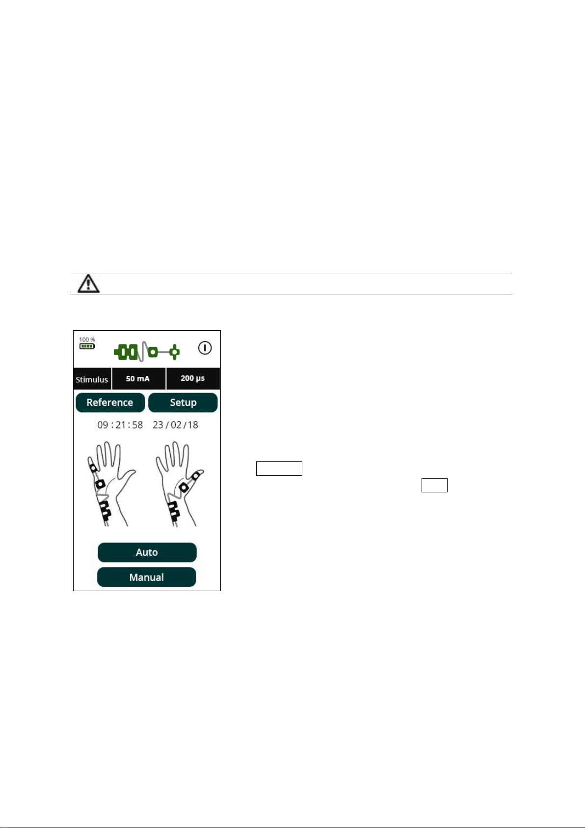
15. Operation
Do not use the monitor if the home screen does not appear.
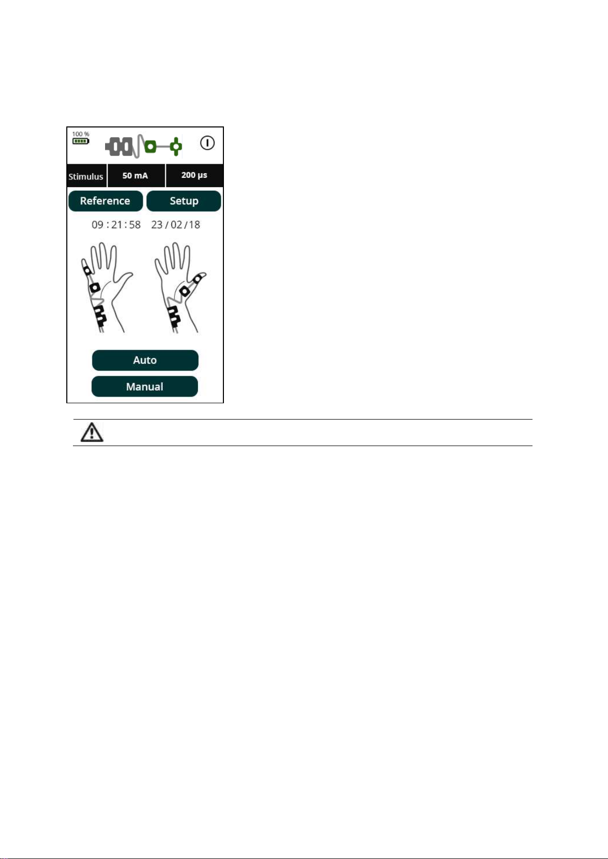
Following the setting up procedure, the home screen appears.
Check that the unit has adequate battery
life, as indicated in the top left corner of
the screen. A 100% battery charge gives
approximately 8 hours of continuous use.
Press Reference to set a reference number
or a patient number. If desired, press Setup
to set time, date and other preferences.

SEN 008
Issue 9.3
23 May 2019 Page 12 of 29
If Setup is selected, the screen to the right
appears:
Use the up and down arrows to change the
date and time. →
Press DD/MM/YY to alternate between the
date format options. →
Press + or - to increase or decrease the
brightness. →
To turn the sound on or off press On/Off. →
Press 50 or 60 to set the filter to the local
mains electricity frequency (Hz). →
Press Delete to erase the log. →
Press OK to return to the previous screen. →
If Reference was selected, the screen to
the left will display.
← Use the keypad to enter a reference
number or a patient number.
← Press backspace to delete an entry.
Press OK to record the Reference Number
and to return to the home screen.
09:21:58
23/02/18
SEN 008
Issue 9.3
23 May 2019 Page 13 of 29
The screen indicates when the electrodes are in
contact with the skin by changing the colour of the
icons for the stimulating and evoked response
sensors.
GREY indicates that the stimulating or recording
electrode pairs are not connected to the patient.
YELLOW indicates that the TetraGraph was unable to
deliver the requested current setting (mA), most
likely due to high impedance at the skin connection.
Check the stimulating electrodes for proper
connection to the patient.
GREEN indicates that the electrode is correctly
connected and the impedance is within acceptable
limits to deliver the requested current and to record
the response.
If required, adjust the locations of the sensors so that
the sensor icons for the hands are GREEN before
proceeding.
Check that the device has adequate battery charge for the procedure before commencing. A full charge
lasts approximately 8 hours of continuous use.

SEN 008
Issue 9.3
23 May 2019 Page 14 of 29
To begin, the unit can be started using
either Auto or Manual setting mode.
During an automatic setup, the unit will
detect the maximal current before the
main test screen appears, and will set the
current to 20% above the point of maximal
response (supramaximal current level).
The parameters for stimulus in
milliamperes (mA) and pulse width in
microseconds (µs) are shown on the
screen following automatic setting. If the
device is unable to reach the maximal
response:
1. The maximum stimulus will be indicated
(300 µs at 60 mA) and paused, allowing
the user to repeat the Auto calibration.
Check the electrodes and perform the
Auto setup again.
2. If the device cannot determine the
maximal stimulation in Auto mode, the
monitor will default to delivering the
maximal stimulus, 60 mA at a pulse width
of 300 µsec. The operator can press Manual
to select Manual mode and set the current
and pulse width appropriately.
Please see section 16 for troubleshooting
solutions regarding the Auto setup.
NOTE: There is no yellow indicator to show when the stimulation capacitors are primed as the capacitors
are continuously primed.

SEN 008
Issue 9.3
23 May 2019 Page 15 of 29
MANUAL MODE
Stimulus current settings: press on the Stimulus button to reveal the parameter
selection menu.
Please see the following figure for all settings within the parameter selection menu.
Press on the required setting to select the desired value and then press OK, or press
OK to return without making changes to the settings.
Pulse Width settings (stimulus duration in µsec).
Interval settings (frequency of stimulation).
Stimulus settings (current intensity in mA).
The Auto flag is displayed if the automatic stimulus
setting was determined and has not been changed.
The Auto flag will disappear if the stimulus settings
are changed.
SEN 008
Issue 9.3
23 May 2019 Page 16 of 29
To start monitoring, press TOF (Train of
Four), or ST (Single Twitch).
During monitoring, data can be displayed in
three different ways: bar graph, trend or
waveform. These options can be accessed
by the three buttons below the graph.
To pause monitoring, press Pause . If pause
is selected, the Pause button will change to
red. Stimulation stops while monitoring is
paused.
← During all 3 monitoring modes, the data
can be displayed as a bar graph, waveform
or trend graph.
The elapsed time indicator at the top of the
screen amongst the parameters shows the
period since the last measurement was
made.
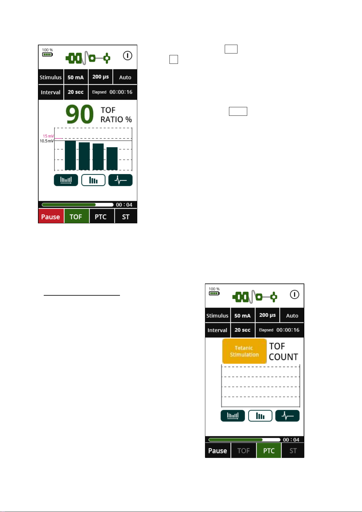
If TOF count reaches zero then PTC option will be enabled, indicated by the PTC
mode button flashing green. PTC mode is then activated by pressing the PTC button.
TETANIC STIMULATION
When a PTC count has finished, further
TOF or PTC measurements will be
prevented for 3 minutes before another
measurement can be made. This interval is
fixed and cannot be changed, even if
shorter intervals have been chosen.
Following a PTC measurement, the
monitoring mode will automatically revert
to TOF.
PTC mode can only be initiated manually
when indicated, after a TOF count of zero.
COUNT
SEN 008
Issue 9.3
23 May 2019 Page 17 of 29
SINGLE TWITCH MODE
Single Twitch (ST) is used in two settings:
1) To determine the onset of paralysis
during neuromuscular relaxation as
a guide for readiness for tracheal
intubation.
2) As part of the PTC sequence, when
a series of up to 20 ST stimuli at a
frequency of 1 Hz are delivered 3
seconds after a 5-sec, 50 Hz tetanic
stimulus.
After a tetanic stimulation, neuromuscular
responses are increased transiently,
resulting in a period of ‘post-tetanic
amplification’. To avoid false assessment
of recovery, operation of ST and TOF
modes will be disabled for 3 minutes after
a tetanic stimulation.
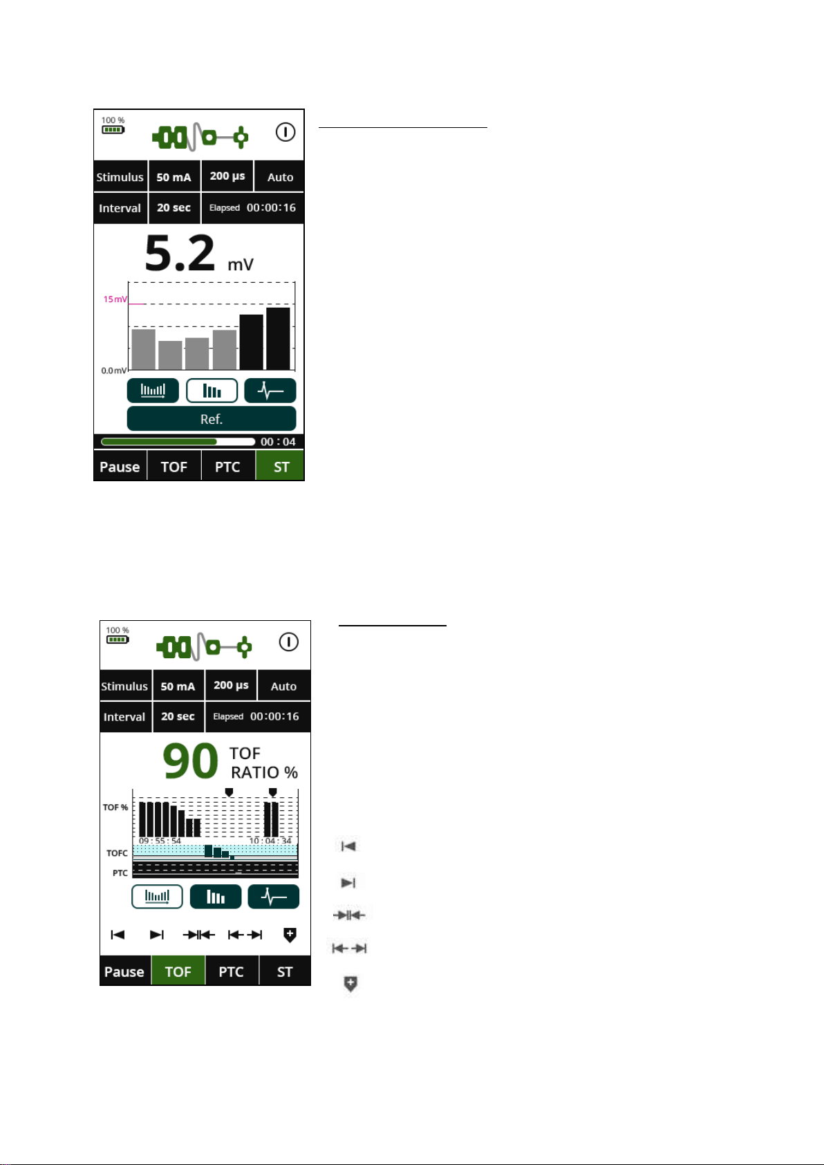
TREND GRAPH
The Trend Graph displays time along the X axis
and the TOF ratio, TOF count and PTC along the Y
axis. The modes in the trend graph are indicated
by TOF Ratio in white, TOF Count in blue and PTC
in black. In the example to the left, the results are
shown throughout the stages of measurement.
The graph controls are explained below:
Move toward beginning of graph
Move toward end of graph
Zoom in
Zoom out
Place a marker
SEN 008
Issue 9.3
23 May 2019 Page 18 of 29
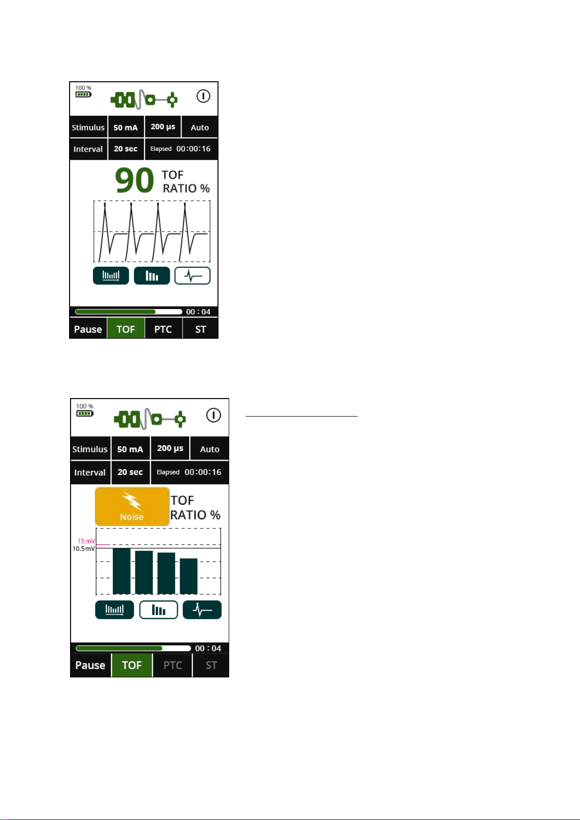
The screen to the left appears once the
waveform button has been pressed during
a TOF measurement.
NOISE NOTIFICATION
The noise notification will appear when any
electromagnetic interference is detected from any
nearby electronic device.
This may be as a result of electrocautery activity
and the monitoring will resume after the
electrocautery interference ceases.
This may also be caused by adjacent equipment.
Ensure the Patient Cable is not in contact with
other electrical equipment.
Other manuals for TetraGraph SEN 2001
1
Table of contents


