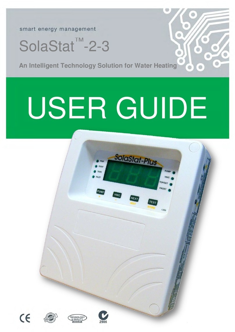
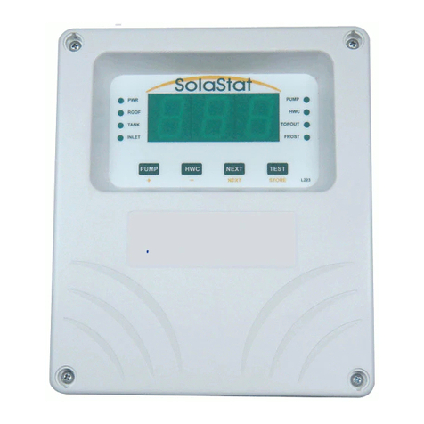
Senztek SolaSmart Plus User manual

INSTALLATION GUIDE
SolaSmart Plus™
www.senztek.com
© Senztek Holdings Ltd. 2011

SolaSmart™ Plus Installation Guide
Version 1.1 – March 2012 Table of Contents
Table of Contents
Before You Begin Installation.................................................................................... 1
Installing the SolaSmart™ Controller......................................................................... 5
Mounting the Sensors and Connecting Wiring........................................................... 7
Powering Up............................................................................................................ 10
Plumbing Tips ......................................................................................................... 14
About the Pump Settings......................................................................................... 16
BioSafe, Reheat, and Boost Functions.................................................................... 18
Operational Settings................................................................................................ 20
Tariff Table.............................................................................................................. 21
Display and Diagnostics.......................................................................................... 22
Sensor Maintenance ............................................................................................... 25
Trouble Shooting Guide .......................................................................................... 27
Specifications.......................................................................................................... 29
For technical help contact your distributor.
Distributor Details:
www.senztek.com
Senztek Holdings Ltd. 2009

SolaSmart™ Plus Installation Guide
Version 1.1 – Mar 2012 Page 1
BEFORE YOU BEGIN INSTALLATION
Assemble the
Components
You Will Need
The SolaSmart™ Controller is supplied with the following components:
Plug In Roof sensor
Tank sensor
Inlet sensor
Mains cable
Pump cable
Associated screws
Screw covers
Continued on next page

SolaSmart™ Plus Installation Guide
Version 1.1 – Mar 2012 Page 2
BEFORE YOU BEGIN INSTALLATION,CONTINUED
Assemble the
Tools You
Will Need
You will need the following tools to install the SolaSmart™:
Philips1 screwdriver for lid screws.
Pozi 2 screwdriver for mounting screws.
NOTE: These tools are needed to mount the SolaSmart™ only, and other
tools may be needed for the remainder of the installation including the
sensors.
READ THESE SAFETY PRECAUTIONS and LIMIT OF LIABILITY BEFORE YOU BEGIN
The following pages contain instructions for qualified personnel only. They involve potentially
hazardous adjustments and high voltage mains wiring information.
General
Safety
Precautions
The following general safety precautions should be noted:
This installation guide is for the installation of SolaSmartTM
The complete installation should be checked at least annually for damage or
malfunction.
Controllers only
and is not an installation guide for any other part.
All servicing must be carried out by an authorised service agent only.
All aspects of the installation must comply with local electrical and plumbing
regulations (and any special solar hot water regulations).
Continued on next page

SolaSmart™ Plus Installation Guide
Version 1.1 – Mar 2012 Page 3
BEFORE YOU BEGIN INSTALLATION,CONTINUED
Installation
Precautions Installers need to ensure the following:
The controller must be installed away from water sources such as rain,
leaking pipes, or wet floors; and must not be installed in damp areas like
bathrooms. The controller must have a waterproof enclosure if it is installed
outside.
Make sure the controller is installed away from direct sunlight, flammable
liquids or radiant heat sources.
Power leads must face directly down, not sideways or upwards.
Ensure the controller is in a safe environment for users to inspect display
panel.
Follow instructions carefully when mounting sensors. Incorrect sensor
mounting can lead to a poorly controlled solar hot water system with safety
issues (e.g. overheating; over pressure damage to the plumbing; freezing
damage to the solar collector).
The unit settings are factory programmed to optimise efficiency and safety.
Alteration of the programmed values can lead to dangerous conditions and/or
damage to parts of the solar hot water system.
CAUTION:
Dangerous Voltages may be present. The SolaSmartTM
Protective enclosure must only be opened by qualified personnel.
has no user
serviceable parts.
Remove ALL power sources before removing protective cover.
Continued on next page

SolaSmart™ Plus Installation Guide
Version 1.1 – Mar 2012 Page 4
BEFORE YOU BEGIN INSTALLATION,CONTINUED
Electrical
Precautions When undertaking electrical installations, please note the following:
All mains voltage electrical work must be carried out by a qualified
electrician, especially external power outlet socket installation.
A readily accessible disconnect device, over current device and RCD
Protection rated to suit the size of the pump plus 5VA must be incorporated
in the power supply wiring. The over current device for a 1500W, 240Vac
pump must not exceed 10Amps.
Sensor leads should be kept 300mm (12 inches) away from mains and
comms cables.
Do not use mains power extension cords unless approved by the
manufacturer. Water resistant plugs and sockets should be used.
The SolaSmart™ controlled output (PUMP) will be connected to the input
power supply wiring and is not isolated from it. Supply voltages will be output
through that outlet during activation.
The HWC outlets are isolated contacts. A supply wire and an output wire will
need to be wired to each HWC outlet.
Always use the unit within specified voltage and load ranges. Never use with
damaged leads, plugs or sockets.
Do not allow the sensor cable to come within 10mm of the high voltage
connectors or components inside the enclosure.
The electric element should have a fuse that is rated within the stated
maximum of the relay driving the element.
Do not connect the mains or the pump to a circuit that could be switched off
by your electricity supplier to manage peak loads (ripple control).
Comply with all local and relevant electrical regulations.
Warning These products are not designed for use in, and should not be used for,
applications which are in conjunction with items that are critical to any
person’s health (e.g. life support systems).
In any critical installation, an independent fail-safe back-up system must
always be implemented.

SolaSmart™ Plus Installation Guide
Version 1.1 – Mar 2012 Page 5
INSTALLING THE SOLASMART™CONTROLLER
Overview The diagram below shows how the SolaSmart™ is connected to the hot
water cylinder (HWC), the collector, and the three sensors (ROOF, TANK
and INLET).
Continued on next page

SolaSmart™ Plus Installation Guide
Version 1.1 – Mar 2012 Page 6
INSTALLING THE SOLASMART™CONTROLLER,CONTINUED
Where to
Mount the
SolaSmartTM
The SolaSmartTM should be mounted so that:
1. It is against a flat surface with sufficient strength to hold the enclosure
and any additional weight from the plugs, sockets and cables,
2. Power Leads face down not sideways or up,
3. It is safe for users to inspect, and
4. Allowance is made for cable runs, location of power outlets and lengths
of wires.
Mounting the
SolaSmartTM Follow these steps:
1. Allow for the enclosure dropping 5mm (1/5 inch) from screw centres once
mounted (keyhole mounting).
2. Place the drill guide template against the wall, checking for level
alignment. Four screws are supplied: two chipboard screws and two
combination plasterboard/wood screws.
All four mounting holes should be used with at least two firmly secured
into wood.
The outer plastic plasterboard anchors will self tap into plasterboard and
their inner metal screws fix into the centre of the plastic anchors.
3. Mark and drill/screw as appropriate leaving the heads of the screws
above the surface by approximately 3mm (1/8 inch).
4. Place the unit over the four screw heads. The unit should slide down
5mm into the ‘key’ slots and become secured to the wall. You will need to
adjust the screw height to obtain a secure fit.

SolaSmart™ Plus Installation Guide
Version 1.1 – Mar 2012 Page 7
MOUNTING THE SENSORS AND CONNECTING WIRING
Introduction The locations and way that the sensors are mounted is critical to ensure the
SolaSmart™:
Operates correctly and at greatest efficiency;
Protects the system against damage from extreme temperatures, and
If the Tank (Upper Tank) and/or Inlet (Lower Tank) sensors are not mounted
correctly:
There may be an inaccurate Topout sensing, which could lead to damage to
the hot water cylinder or other components.
There may be an inaccurate BioSafe sensing, which could increase the risk
of biological contamination.
If the ROOF sensor is not correctly mounted:
The unit may not be able to detect FROST settings (this can lead to the
collector panel bursting).
Please follow the instructions below carefully.
Positioning
the ROOF
Sensor
The ROOF sensor should be fitted into a metal immersion ‘pocket’ in the hot
water outlet pipe.
Apply plenty of heat transfer compound (available from your distributor)
between the sensor and the lining of the hot water outlet pipe.
Seal the sensor with neutral cure sealant and install external lagging. The
cable should also be insulated from the bare pipe.
Ensure that the sensor cable is NOT in contact with the solar collector or any
other exposed metallic surface on the roof.
Secure the ROOF sensor cable so it cannot move in strong winds. This is
important to stop wire fatigue breakages.
To prevent physical damage to the cable by birds and vermin it is
recommended that the cable is run in appropriate electrical conduit that will
prevent damage to the sensor cable. The conduit needs to be run from the
collector to the controller such that all cable is protected. Make sure the
conduit is not in contact with the collector such that heat damage could occur
to the conduit.
Continued on next page

SolaSmart™ Plus Installation Guide
Version 1.1 – Mar 2012 Page 8
MOUNTING THE SENSORS AND CONNECTING WIRING,CONTINUED
Positioning
the Tank
(Upper Tank)
Sensor
Positioning
the Inlet
(Lower Tank)
Sensor
The Tank (Upper Tank) Sensor must always be fitted above the Solar
Collector return pipe. Labelled ‘TANK’ on the circuit board.
WARNING: Damage to the Hot Water Cylinder can occur if the Upper Tank
sensor is not mounted correctly.
The Upper Tank sensor should be fitted into a metal immersion ‘pocket’ in
the upper region of the hot water cylinder (HWC) (typically 1/3 of the way
down from the top of the HWC).
If a ‘pocket’ is not available, then bond the sensor against the metal wall of
the tank (not the outside cladding or insulation). Senztek has an ‘S3’
mounting option
Apply plenty of heat transfer compound (available from your distributor)
between the sensor and the lining of the ‘pocket’ (or between the tank and
the sensor).
If the tank is outdoors then seal where the cable exists the hot water tank
with neutral cure silicon.
The Inlet (Lower Tank) sensor should be fitted into a metal immersion
‘pocket’ above the HWC electric element near the bottom of the tank (usually
just above the element). Labelled ‘INLET’ on the circuit board.
If a ‘pocket’ is not available, then bond the sensor against the metal wall of
the tank (not the outside cladding or insulation). Senztek has an ‘S3’
mounting option
Apply plenty of heat transfer compound (available from your distributor)
between the sensor and the lining of the ‘pocket’ (or between the tank and
the sensor).
Precautions Please note:
Removing or cutting the cladding may void the hot water tank warranty.
The sensor must not be immersed in water.
Unless the temperature probe is designed for immersion in water,
temperature probe pockets need to be completely dry before you insert the
probe; and the pocket must be protected against moisture entry after the
probe is fitted.
Sensor leads should be kept 300mm (12 inches) away from the mains and
communications cables.
Make sure the right sensors are mounted in the right places!
Continued on next page

SolaSmart™ Plus Installation Guide
Version 1.1 – Mar 2012 Page 9
MOUNTING THE SENSORS AND CONNECTING WIRING,CONTINUED
Connect the
Wiring The SolaSmart™ is supplied pre-wired with mains plug and pump socket,
tank and inlet sensors.
1. Connect the wiring from the SolaSmart™ Controller to the ROOF sensor,
the TANK sensor and the INLET sensor.
2. Connect the mains wiring.
3. Connect the wiring for the hot water cylinder element.
4. Connect the wiring from the SolaSmart™ Controller to the pump.
2. Connect the
wiring from the
controller to the,
the TANK sensor
and the INLET
sensor (as
labelled).
Plug in the ROOF
sensor.
1.
Connect the
mains wiring.
Do NOT
connect the
mains wiring
to a circuit
that could be
switched off
by your
electricity
supplier to
manage peak
loads (ripple
control)
3. Single Element HWC:
Connect the wiring from the controller to the hot water
cylinder element. Lower element or single element
Make sure that the electric element has a fuse that is
rated within the stated maximum of the relay driving the
element.
This is a simple (clean) set of normally open contacts
that interrupt the Active/Phase wire that powers the
element.
Do not bypass any thermostats or cut-outs.
Ensure mechanical thermostat is adjusted to maximum
so controller can operate HWC.
NOTE:WIRING OF HWC MUST BE DONE BY A REGISTERED
ELECTRICIAN.
4. Dual Element HWC:
Connect the wiring from the controller to the hot water
cylinder element. Upper element in a dual element tank
Make sure that the electric element has a fuse that is rated
within the stated maximum of the relay driving the element.
This is a simple (clean) set of normally open contacts that
interrupt the Active/Phase wire that powers the element.
Do not bypass any thermostats or cut-outs.
Ensure mechanical thermostat is adjusted to maximum so
controller can operate HWC.
NOTE:WIRING OF HWC MUST BE DONE BY A REGISTERED
ELECTRICIAN.

SolaSmart™ Plus Installation Guide
Version 1.1 – Mar 2012 Page 10
POWERING UP
Before you
Connect the
Power
Before you power up, make sure you have:
Read the safety instructions, warnings and liability statements.
Completed installation.
Securely mounted the unit in place before you connect power to the unit.
Checked that no water, metal shavings or other electrical hazards are
anywhere near the plug, socket and/or surrounding environment.
NOTE:
The power outlet socket must be installed by a registered electrician.
The SolaSmart™ must be installed by a qualified person.
Ensure suitable over-current protection and RCD protection for the
SolaSmart™ is in place.
The mechanical hot water thermostat for the electric element should be set
to the maximum for the HWC Control Mode to operate correctly. (The hot
water thermostat is only used as a failsafe feature and normally will not
operate.)
Continued on next page

SolaSmart™ Plus Installation Guide
Version 1.1 – Mar 2012 Page 11
POWERING UP,CONTINUED
What you will
see Before you power up, make sure you have:
Read the safety instructions, warnings and liability statements.
Completed installation.
Securely mounted the unit in place before you connect power to the unit.
Checked that no water, metal shavings or other electrical hazards are
anywhere near the plug, socket and/or surrounding environment.
NOTE:
The power outlet socket must be installed by a registered electrician.
The SolaSmart™ must be installed by a qualified person.
Ensure suitable over-current protection and RCD protection for the
SolaSmart™ is in place.
The mechanical hot water thermostat for the electric element should be set
to the maximum for the HWC Control Mode to operate correctly. (The hot
water thermostat is only used as a failsafe feature and normally will not
operate.)
Continued on next page
The CONTROLLER OK
light is on when the
controller is operating
correctly.
The PUMP light comes on when the
pump is on (in normal or FROST
operation or when the PUMP button
is pressed).
For Dual Element model:
The HWC2 light comes on when
upper element is on.
The HWC1 light comes on when
element is on.
HWC Button
Press for Boost; press again to
cancel boost.
The SENSORS OK light
is on when the sensors
are operating correctly.
Light off; check Roof
sensor.
Light flashing; check Tank
sensor.
PUMP Button
Press and hold this button to turn the pump
on, and release to turn the pump off.
To keep the pump running, press and hold
button until pump light is flashing; and press
again to turn pump off.

SolaSmart™ Plus Installation Guide
Version 1.1 – Mar 2012 Page 12
POWERING UP,CONTINUED,CONTINUED
Setting the
Time and Date The display is accessed by taking the top cover off the unit. Care must be
taken in these conditions as there are dangerous voltages present around
the high voltage section of the PCB. There is a plastic sheath fitted around
this area under normal conditions. The Setting Time and Date procedure is
also printed on the plastic sheath.
Procedure:
1. Press the Set Button.
2. Press the Hour and Min buttons to adjust time.
3. Press the Set Button.
4. Press the Day and Month buttons to adjust date. Year not set.
5. Press the Set Button.
Continued on next page

SolaSmart™ Plus Installation Guide
Version 1.1 – Mar 2012 Page 13
POWERING UP,CONTINUED,CONTINUED
Final Checks The SolaSmartTM is now fully installed and should be working.
It is best to observe some solar hot water pump cycles, but this will depend
on the sun shining.
Check all functions are working correctly before leaving the installation.
The SolaSmart™ settings have been factory set to the standard settings for
your area and requirements.
See ‘Trouble Shooting’ section on pages 27-28 of this guide if the system is
not working correctly.

SolaSmart™ Plus Installation Guide
Version 1.1 – Mar 2012 Page 14
PLUMBING TIPS
Overview This section will help you to ensure the plumbing associated with the
SolaSmart™ will enable the system to be operated safety and to maximum
efficiency.
All plumbing installations should be carried out by registered and qualified
plumbers and all regulatory and local standards must be applied. Best
plumbing standards must be used for all plumbing work associated with
installation and maintenance.
All parts including the pump must be rated for the elevated temperatures
found in solar hot water systems.
The information provided here provides feedback from experienced solar hot
water professionals, but does not represent a complete guide to plumbing a
system.
Tempering
Valve Water from solar hot water collectors frequently reaches very high
temperatures. It may exceed 100°C (under pressure).
A tempering (or mixing) valve must be installed if required by local
regulations.
It is used to ensure the supply from the tank does not burn end users. The
tempering valve must be appropriately rated to handle extreme
temperatures.
Installation must be to best plumbing practice and the manufacturer’s
specifications.
Non Return
System Hot water rises and cold water falls. If the solar collector is colder than the
tank (e.g. at night) the hot water from the tank can thermo-siphon up to the
collector. The collector then radiates the heat to the cool night air and the
cooler water descends back to the tank.
To stop this loss of hot water at night or during cloudy skies, a ‘one way’ or
non-return valve or other non return solution needs to be fitted.
The failure of a non-return valve or heat loop is a common problem with solar
hot water systems. Some key points are:
It is critical to make sure that the orientation of the valve is as per the
manufacturer’s directions.
Make sure there are no debris caught in the valve as that could cause the
valve not to close.
The heat loop/trap is long enough.
Continued on next page

SolaSmart™ Plus Installation Guide
Version 1.1 – Mar 2012 Page 15
PLUMBING TIPS,CONTINUED
Pressure
Relief Valves Solar hot water systems can run much hotter than standard domestic hot
water systems. Hotter water expands more, and needs high quality pressure
relief valves to ensure the tank or other components do not burst under
pressure.
A qualified plumber can recommend the best practice solution for each
installation for pressure relief valves, including the number and placement of
them.
Air Relief
Valves Air locks can occur within the piping system (as well as the pump). These
can increase the pressure that the pump is working against, to the point
where the pump can no longer circulate the water.
To avoid this, an air relief valve should be fitted (especially in low pressure
systems).
Your registered plumber should install the air relief valve to the highest point
of the return from the solar water collector.

SolaSmart™ Plus Installation Guide
Version 1.1 – Mar 2012 Page 16
ABOUT THE PUMP SETTINGS
Introduction The SolaSmart™ works by turning the pump on when the difference between
the temperature at the solar hot water collector (ROOF) and the INLET is at a
high level (i.e. the temperature at the solar hot water Collector is significantly
higher than the temperature at the bottom of the tank (INLET).
The pump turns off again when the difference is lower (i.e. the water in the
tank has been heated up).
For example, using the standard settings:
PUMP ON = 12°C and PUMP OFF = 6°C:
When the solar hot water collector (ROOF) water temperature is 12°C higher
than the INLET, the pump turns on. This transfers hot water from the
collector to the tank, and transfers cooler water from the bottom of the tank to
the collector.
This makes the temperature in the Tank heat up; and the temperature in the
collector on the ROOF cool down.
When the difference in the two temperatures reduces to 6°C, the pump
switches off, allowing the water in the collector to heat up again.
FROST
Function
The FROST function is designed to protect your collector and hot water
system from freezing and bursting. When this temperature is reached, the
pump will come on just enough to raise the temperature of water by 2-3°C
Only a small amount of warm water is needed to protect the collector and
plumbing.
When the unit is in Frost Mode, the PUMP light will come on.
PWM Pump
Function
The PWM output is a signal that can communicate with an intelligent variable
speed pump such as the Grundfos Solar PM 15-85. This is a signal only and
not a power source.
A PWM pump uses less electricity to pump the same amount of water as a
standard induction pump and will harvest solar energy more efficiently with
the SolaSmart controller using a control method that self adjusts to maximum
energy transfer.
Continued on next page

SolaSmart™ Plus Installation Guide
Version 1.1 – Mar 2012 Page 17
ABOUT THE PUMP SETTINGS,CONTINUED
Advanced
TopOut
Function
The Topout temperature is the maximum temperature that you will allow in
the cylinder. Very high temperatures in the cylinder can cause damage
(especially for ceramic lined tanks) – both from heat, and from high
pressures on plumbing fittings.
This function is designed to stop hotter water from the collector entering the
cylinder if the temperature is already high – until the water in the cylinder has
cooled down to a safe level.
Senztek has also developed an advanced Topout method that delays the
onset of collector stagnation and facilitates early recovery if stagnation has
occurred.
This is achieved by using a three stage Topout where the tank is protected at
all times and the solar pumping control method is altered progressively.
If stagnation has occurred and the hot water tank is no longer at maximum
then recovery is achieved by pulsing water through the collector, dissipating
heat in the pipes such that steam should not be present when the water re-
enters the tank and thus avoiding steam implosions (loud banging noises in
tank).

SolaSmart™ Plus Installation Guide
Version 1.1 – Mar 2012 Page 18
BIOSAFE,REHEAT,AND BOOST FUNCTIONS
Collector
BioSafe During BioSafe the pump is run for two minutes once the tank is above the
target temperature.
BioSafe Mode
BioSafe runs periodically according to the settings. Only Inlet (Lower Tank)
Sensor is used and Lower Element will be turned on when the controller is in
the BioSafe Mode.
For installations where the Inlet (lower tank) sensor is below the electric
element, BioSafe must use the Tank (upper tank) sensor for control and
should be set to run every 24 hours to comply with AS 3498 Clause 7.1 (j)
BioSafe uses the Real Time Clock to determine when it should run and is
therefore immune to power outages less than 14 days.
BioSafe Target
The controller ensures that the whole tank is above this temperature during
BioSafe Mode.
BioSafe Holdup
The time BioSafe Target Temperature will maintain before exiting BioSafe
Mode. If Lower Tank Temperature drops below BioSafe Target Temperature,
the holdup timer is reset for the full BioSafe Holdup.
BioSafe Band
BioSafe can be specified to run at the start of any of the four Tariff band.
(Refer to “Tariff Table” on page 21)
BioSafe Period
It is the interval that BioSafe takes to repeat its operation, nominally every 7
days.
Continued on next page
Other manuals for SolaSmart Plus
1
Table of contents
Other Senztek Controllers manuals
Popular Controllers manuals by other brands
Astral Pool
Astral Pool ASTRAL VIRON CONNECT 10 Setup and operation manual
Contro l4
Contro l4 EA-5 installation guide
wattstopper
wattstopper DRD8 v2 installation instructions
Show Tec
Show Tec Showmaster 48 MKII manual

digitalview
digitalview HSP-1920v2 instructions

Kieback&Peter
Kieback&Peter DDC4400e Product description
