Seon Mobile Surveillance Smart-Reach User manual

700-0067
R003
1
*700-0067*
Smart-Reach™ Install and Setup Guide
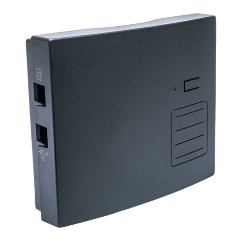
The Smart-Reach Mobile wireless bridge links the mobile DVR to the wireless network.
Package Contents (typical)
The contents of a typical installation package are shown below. The actual contents of your installation
package may vary.
Location Requirements
Find the appropriate location for the installation of the Smart-Reach Mobile and the antenna that meets
these requirements.
• The antenna must be installed within 6 feet of the Smart-Reach Mobile.
• The Smart-Reach Mobile must be installed in a dry location.
• The antenna should be installed on the top of bus, in a location that has best visibility to the Access
Point antenna, typically in the middle of the roof on the front of the bus.
Antenna Requirements
Attaching the antenna to the vehicle will require one person outside and one person inside.
For more information, see the product documentation that is included with the supplied antenna:
• Larsen LPT2400NMOHF antenna
• Laird Technologies TRA58003 antenna
Smart-Reach Mobile wireless bridge • Mobile antenna, 2.4 GHz or 5.8 GHz
• Antenna connector harness
• Optional: Ground Plane
WARNING: Surge Protection and Grounding
When connecting an outdoor antenna to the Smart-Reach Mobile, make sure that proper lightning
surge protection and grounding precautions are taken according to local electrical code.
Failure to do so may result in personal injury, fire, equipment damage, or a voided warranty.
2.4
GHz 5.8
GHz

2
700-0067
R003
Smart-Reach Installation Guide
Installation
General Installation Diagram
To Battery
To Ground
3AFuse
Serial port
Reset
button
Main antenna
connector
Wireless
light
Power light
Ethernet
light
Antenna
If Using Smart-Link Option
TL4 DVR Rear Panel
Smart-Link™
POWER IN
SIGNALS
POWER ON
LOW VOLTAGE
ALARMS AUX.
POWER INDICATOR
PAN EL
POWER OUT
TO DVR
GPS
CAN
SPEED
GPS
DB-9

700-0067
R003
3
Smart-Reach Installation Guide
Installing the WLAN Antenna and Connector Harness
Use the following image and procedure to install the antenna to the connector harness.
1Drill a 5/8" hole on a flat surface of the vehicle.
A fiberglass surface is less than optimal for installing the antenna connector harness. If the vehicle skin
is not metal, Seon Design will provide a ground plane. Contact Seon Design for more information.
2Remove any drill burrs on the edge of the hole.
Metal-to-metal contact between the vehicle and the antenna assembly provides the best performance.
3On the connector harness, remove the threaded antenna connector from top of the main assembly.
4Keep the small locking washer on the main assembly.
5If installing the 2.4 GHz antenna, remove the metal center pin and white plastic insulator from the top
of the main assembly.
6If the ground plane is required, (i.e. with the 5.8 GHz antenna), place the supplied ground plane over
the main assembly to rest on the mounting step.
7From the inside, insert the mounting assembly through the vehicle hole and hold it so that the mounting
step limits how far the assembly passes through the vehicle hole.
8From the outside, thread the antenna connector onto the main assembly until it stops firmly on the
locking washer, (60 in-lbs. or 6.8 Nm maximum). Do not over tighten.
9From the inside, thread the mounting step until it stops firmly against the inside surface of the vehicle
(60 in-lbs. or 6.8 Nm maximum). Do not over tighten.
10 From the outside, thread the antenna onto the antenna connector until it stops firmly on the connector,
(60 in-lbs. or 6.8 Nm maximum). Do not over tighten.
Locking Washer
Antenna Connector
Mounting Step
Main Assembly
Hole - 5/8” Diameter
Center Pin and
Insulator Removed
2 GHz Install Diagram
Vehicle Surface
2.4 GHz Antenna
Mounting Step
Main Assembly
Locking Washer
Antenna Connector
Hole - 5/8” Diameter
Center Pin and
Insulator Installed
5 GHz Install Diagram
Antenna Ground Plane
Vehicle Surface
5.8 GHz Antenna

4
700-0067
R003
Smart-Reach Installation Guide
Installing the Smart-Reach Mobile
1Secure the Smart-Reach Mobile to the mounting surface using the four #10 × ¾ sheet metal screws or
the #10 × ¾ self drilling screws and #10 external lock washers.
2Connect as shown in the General Installation Diagram on page 2.
3Connect the Ethernet cable to the DVR.
4Connect the antenna cable to the socket on the Smart-Reach unit. In a typical installation, the external
antenna must be connected to the main antenna connector of the Smart-Reach Mobile (on the same side
as the other connectors).
5Connect the control cable to the CONTROL port on the DVR.
If using the Smart-Reach with MX or DX Series DVRs and Smart-Link, connect the control cable to
the AUX POWER port on the Smart-Link.
6Connect power connector to a good battery source.
Configuring the System
The Smart-Reach Mobile comes pre-configured for your network. The following DVR settings must be
configured properly:
1The network settings must be configured as instructed by Seon Design.
2The power off delay time should be set long enough to allow video to be downloaded after the bus
ignition is turned off, typically two hours.
Powering the System to On
1Turn the vehicle ignition on.
• When the DVR is powered on, the Power light on the Smart-Reach should flash for a short period of
time, then turn on.
• During startup, the Ethernet light flashes, indicating a proper Ethernet connection with the DVR.
• After the DVR starts up, the Ethernet light on the DVR turns on. If the Ethernet light doesn’t flash or
turn on, check the Ethernet connection between the DVR and the Smart-Reach.
• If the Smart-Reach Base is already installed, the Wireless light flashes occasionally, indicating a
connection to the wireless network.
2Park the vehicle in a location that is line-of-sight from the base antenna. From the base host computer,
ping the IP address of the installed bridge (see Using the Ping Command on page 5).
CAUTION
Shielded Ethernet cables must be used for all connections.
Antenna
connector on
Smart-Reach
Mobile unit

700-0067
R003
5
Smart-Reach Installation Guide
Testing the Wireless Network
The Smart-Reach Mobile is pre-configured to operate with your wireless network.
1Enable your computer’s wireless network interface, and set a static IP address that doesn’t interfere
such as 172.24.1.10.
For example, in Windows XP, use Control Panel > Network Connections > Local Area Connection
> Properties > Internet Protocol (TCP/IP) > Properties.
2Connect to the wireless network. For example, from the Windows XP Start menu, select Settings >
Network Connections > Wireless Network Connections. The list of available wireless networks
appears. Select Seon Network (default) and then Connect.
3Confirm that you can browse other devices using the wireless network.
The status lights provide the following information.
Using the Ping Command
1For example, in Windows XP, on the Start menu, click Run.
2Type cmd and click OK.
3In the command line type ping xxx.xxx.xxx.xxx (the IP address of the machine you wish to
contact).
Light State Description
Power On Smart-Reach Mobile is fully operational.
Flashing Smart-Reach Mobile is starting up. If the power light continues to flash
after several minutes, the firmware has failed to load. Reset or power
cycle the Smart-Reach Mobile. If this condition persists, contact Seon
Off Smart-Reach Mobile has no power.
Ethernet On Illuminates for a short time when the link is established.
Flashing Ethernet port is transmitting or receiving data.
Off Ethernet port is not connected or there is no activity.
Wireless Blinking rapidly Smart-Reach Mobile is searching for an access point.
Flashing Wireless port is transmitting or receiving data.

700-0067
R003
6
Smart-Reach Installation Guide
4If you successfully ping the machine, you will get a reply as shown.
5If your ping is not successful, your requests will time out or you will receive a notice that the recipient
could not be contacted.
Configuration
The Smart-Reach Mobile wireless bridge has pre-configured Seon default settings. To make minor changes
to the configuration, read through this section. The Smart-Reach Mobile is managed via its Web-based
management software using Microsoft® Internet Explorer® 7.0 or Mozilla Firefox®2.0 or higher
versions.
Configuring the Network Settings of your Computer
1Connect the LAN port on your computer to the Ethernet port on the Smart-Reach Mobile.
The Smart-Reach Mobile supports automatic crossover detection. However, problems can occur when
connected to older 10BaseT-only interfaces. A crossover cable may be needed when connecting to
older network interface cards (NICs).
2Configure your computer to use a static IP address in the range 172.24.1.2 to 172.24.1.254. (These IP
addresses are typical.) The subnet mask, default gateway and DNS server are configured automatically.
For example, in Windows XP, use Control Panel > Network Connections > Local Area Connection
>Properties >Internet Protocol (TCP/IP) > Properties.
3Disable any wireless connections on your computer.
CAUTION: Wireless Security
To provide easy wireless access to the Web-based management interface, the Smart-Reach Mobile
ships with all wireless security options disabled. Seon strongly recommends that once the Smart-
Reach Mobile is installed, you enable a wireless security option to properly safeguard the wireless
network.

700-0067
R003
7
Smart-Reach Installation Guide
Accessing the Smart-Reach Mobile
1Configure your computer to reconnect the unit.
For example, in Windows XP, use Control Panel > Network Connections > Local Area Connection
> Properties > Internet Protocol (TCP/IP) > Properties, and enter an IP address in the same subnet.
2Relaunch the Smart-Reach Mobile management tool.
FCC Information to the User
This equipment has been tested and found to comply with the limits for a digital device, pursuant to Part 15
of the FCC rules. These limits are designed to provide reasonable protection against harmful interference
in a residential installation. This equipment generates, uses, and can radiate radio frequency energy. If not
installed and used in accordance with the instructions, it may cause harmful interference to radio
communications. However, there is no guarantee that interference will not occur in a particular installation.
If this equipment causes harmful interference to radio or television reception, which can be determined by
turning the equipment off and on, the user is encouraged to try to correct the interference by one or more of
the following measures:
• Reorient or relocate the receiving antenna.
• Increase the separation between the equipment and the receiver.
• Connect the equipment into an outlet on a circuit different from that to which the receiver is connected.
• Consult the dealer or an experience radio/TV technician for help.
CAUTION: Wireless Security
To provide easy wireless access to the management interface, the Smart-Reach Mobile ships with
all wireless security options disabled. Seon strongly recommends that once the Smart-Reach
Mobile is installed, verify the wireless security option to properly safeguard the wireless network.
Important: To perform any additional configuration, assign an IP address, or to reset the Smart-Reach
Mobile wireless bridge, and operating information, contact Customer Service.

700-0067
R003
8
Smart-Reach Installation Guide
Warranty
Seon Design Inc. (Seon) warrants the components listed below against defects in workmanship and
materials provided that such defects appear or are discovered within the respective periods specified below
and provided further that the purchaser of such products notifies Seon of such defects within thirty (30)
days of the appearance or discovery of such defects:
• Three (3) years from date of purchase, parts and labor on all Cameras
• Three (3) years from date of purchase, parts and labor on the Explorer® Premier, DX, TX, EX,
MX, and Trooper® TL series mobile DVR Systems
• One (1) year from date of purchase, parts and labor on the Smart Reach® Wireless systems and
other Wireless products
• One (1) year from date of purchase, parts and labor on all other products and accessories
All service/replacement parts and repairs are warranted for a period of 90 days.
Customer Service Contact Information
© January 2013. Seon Design Inc. All rights reserved. Printed in Canada www.seon.com
Table of contents

