Sequoia TubTop 72-80 User manual
TubTop™
Sequoia Spa Shelters™ by Sequoiaworks Inc.
Assembly Guide for the
TubTop™
Version 7—January 10, 2017

TubTop™
Sequoia Spa Shelters™ by Sequoiaworks Inc.
Introducon
Thank you for purchasing the TubTop™ spa enclosure manufactured by Sequoiaworks Inc™. Please preview the enre set of in-
strucons before starng the installaon. The instrucons are divided into the different steps required for assembly. This enclo-
sure is made in various sizes to fit many different portable hot tubs. Thus, there may be some differences from one installaon to
the next.
The size of the TubTop MT™ is generally matched to the dimensions of the portable hot tub. The model size of the MT is sized
within a couple of inches to the size of the hot tub. For example, a model 84-84 MT would fit a hot tub that has dimensions of 84
inches x 84 inches, but would also fit a hot tub that measures 83 inches x 83 inches, or 85 inches x 85 inches. The MT side dimen-
sion referred to in these instrucons is the length of the wall of the building not including the corner panels.
Note: the term “Spa” and “Hot Tub” are interchangeable. Both are used by manufacturers to describe the same type of product.
Required tools for assembly
-Powered screwdriver with at #2 cross-p (Phillips) bit.
-Measuring tape (either U.S. or metric), 12 . minimum
-6 . step ladder
Unpacking notes
All component packages are labeled so as to idenfy the contents. For the purpose of part idenficaon open packages in se-
quence as required for each assembly step. When uncrang and unpacking the components of the TubTop™, care should be used
to avoid damage to the parts. The components are easily damaged by mishandling. Be extra careful when using knives and other
sharp objects in removing packaging material. Do not set components directly on to rough surfaces. Use padding or packaging
material to protect the component from abrasion.

TubTop™
Sequoia Spa Shelters™ by Sequoiaworks Inc.
Clearances:
Below are the approximate clearances required for the TubTop™.
They will vary slightly depending on the size of the portable spa and
the model size of the building.
Top View*
Elevaon view*
Outer dimensions of wall and roof lines:
Model
Size
Building
Width
“BW”
Building
Length
“BL”
Roof
Width
“RW”
Roof
Length
“RL”
72-80 88” 96” 109” 117”
80-80 96” 96” 117” 117”
84-84 100” 100” 121” 121”
88-88 104” 104” 125” 125”
92-92 108” 108” 129” 129”
74-88 90” 104” 111” 125”
80-88 96” 104” 117” 125”
80-92 96” 108” 117” 129”
96-92 112” 108” 133” 129”
100-92 116” 108” 133” 129”
*Typical installaon. Control side may vary on some models.

TubTop™
Sequoia Spa Shelters™ by Sequoiaworks Inc.
Parts List (in the order that they are installed):
i Support brackets (qty. 4)
i Shelf (qty. 2)
i [Filler strip – opon for cover li installaon] (qty. 2)
i Corner panel (qty. 4)
i Wall panels ( 4 total)
¡ Corner mounted solid wall (qty. 1)
¡ Shelf mounted door wall (qty. 2)
¡ [Shelf mounted open wall – opon: replaces door wall]
¡ Corner mounted door wall (qty. 1)
¡ [Corner mounted open wall – opon: replaces door wall]
i Roof panel ( 8 total)
¡ RH secon (qty. 4)
¡ LH secon (qty. 4)
i Flashing (qty. 4)
i Skylight aachment frame (qty. 4)
i Skylight (qty. 1)
i Skylight aachment L-molding (qty. 2)
i Hip caps (qty. 4)
i End caps (qty. 4)
i Doors (qty. 3 on standard model, open wall does not require door)
Hardware & fasteners:
i W-brackets (qty. 8)
i 2 ½” wood screws (qty. 102)
i 3” wood screws (qty. 36)
i #8 x 1 ¼” pan head screws (qty. 26)
i #8 x ¾” pan head screws (qty. 10)
i #8 x ½” self-drilling pan head screws (qty. 18)
i #6 x 1 ¼” wood screws (qty. 7)
TubTop™
Sequoia Spa Shelters™ by Sequoiaworks Inc.
Support Brackets
There are two methods of supporng the TubTop:
Typically the ground support bracket is used. However, skirt
mounted brackets are available when an adequate deck sur-
face is not available. The interior framing of the hot tub must
be sturdy enough to support the weight of the TubTop for use
of the skirt mounted brackets. Contact us for details.
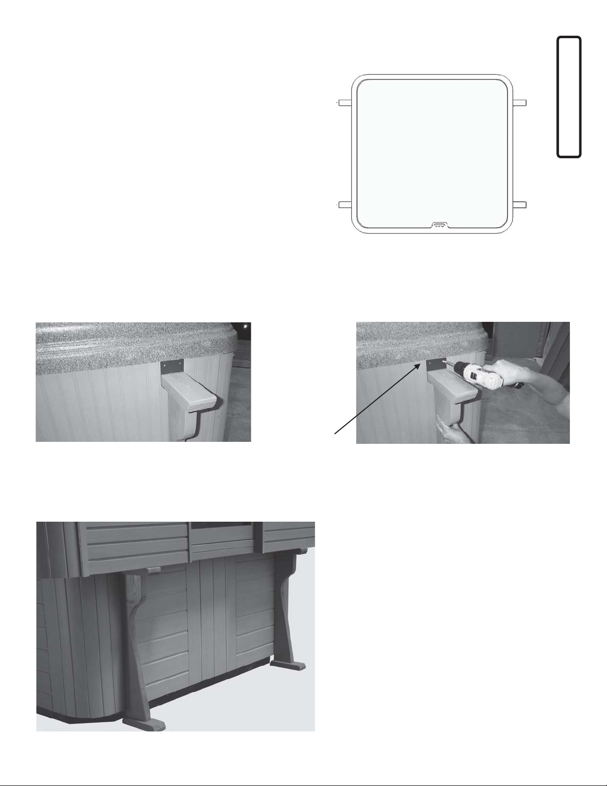
Ground Support Brackets
The support brackets are fied to each hot tub model and are
designed to set on the ground and connect to the skirng just
below the lip of the hot tub shell.
The control access door for the spa is normally on the same
side as the control panel. Be certain that the brackets will not
interfere with its removal.
Place the support bracket as near the start of the
radius corner of the hot tub. Place so as not to
interfere with any access panels for the hot tub.
Use #8 x 1 1/4” pan head screws to fasten the
metal connector at the bracket into the side of the
spa.
Two #8 x 1 ¼” pan
head screws

TubTop™
Sequoia Spa Shelters™ by Sequoiaworks Inc.
Support Brackets
Skirt Mounted Brackets
Locate the aachment points for the spa on the Table AB-1. If
the spa is not listed, please contact us for informaon. Four
brackets are aached to the frame of the spa through the exte-
rior skirng of the portable spa. The typical installaon is to
aach two brackets on each adjacent side of the control panel
side. Note: Not all portable spas have adequate framing to sup-
port the weight of the enclo-
sure. We do offer alternave
soluons for these situa-
ons.
The control access door for
the spa is normally on the
same side as the control
panel. Be certain that the
brackets will not interfere
with its removal.
Place the aachment bracket just below the lip of
the spa shell.
Use #8 x 1 1/4” pan head screws to fasten the top
of the bracket into the side of the spa.
Use one #10 x 3 ½” to fasten the bracket leg to the
side of the spa.
Two #8 x 1 ¼” pan
head screws
One #10 x 3 ½”
wood screw

TubTop™
Sequoia Spa Shelters™ by Sequoiaworks Inc.
Posion shelf rails:
Place the shelf rails on top of the aachment brack-
ets. Align the front end of the two rails so that they
are 4 inches beyond the control side of the spa. Use
the chart below to determine the distance apart to
place the rails. Temporarily fasten the rails to the
brackets from the underside of the bracket with one
2-1/2” screw per bracket. (the rail may need further
adjustment later)
Side Length
Distance “SD”
(inches)
72 83 1/2
74 85 1/2
76 87 1/2
80 91 1/2
84 95 1/2
88 99 1/2
92 103 1/2
Shelf rails
Place the shelf on top of the aachment brackets. Posion the front end of the shelf so that the end is 4
inches beyond the control side of the spa. (Use a
straight edge as an aid)
Determine the distance away from the side of the spa
using the table above. (Distance from spa side = the
distance “SD” minus the spa width then divide by 2.)
Fasten the shelf to the bracket with one #8 x 2 ½” wood
screw. (This may need to be removed and the shelf
adjusted when installing the wall panels)
One #8 x 2 ½”
wood screw
TubTop™
Sequoia Spa Shelters™ by Sequoiaworks Inc.
Corner panel
If using a Cover Valet cover li (oponal):
Some installaons require a filler strip to wid-
en the shelf. The purpose of the filler strip is
to close the space between the shelf rail and
the spa lip. It is also required for installing a
“deck mounted” cover li device.
Fasten the filler strips to the side of the shelf
rails using 2 1/2 inch screws. Locate the filler
strip 4 inches from the front end of the shelf
rail. This will put the filler strip even with the
edge of the spa. The length of the filler strip is
the same as the dimension of the spa.
4”
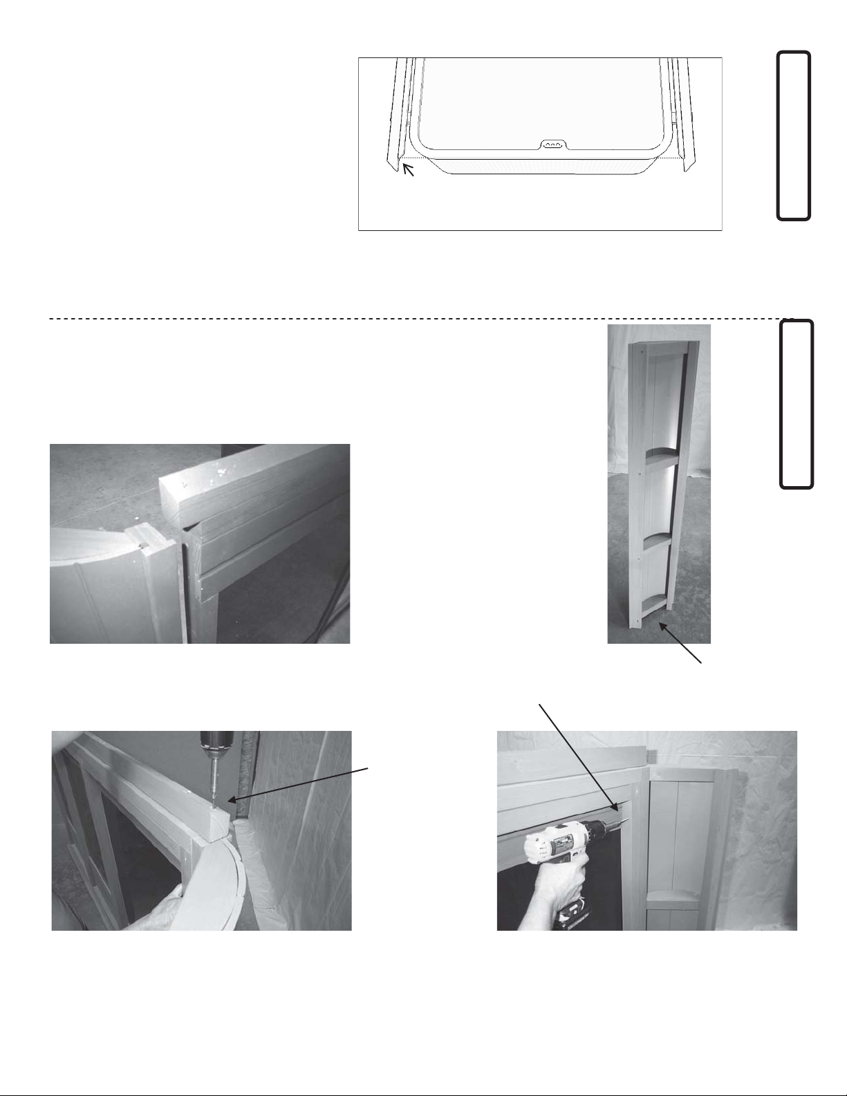
With the shelves temporarily fastened to the aachment brackets, the four
walls are then posioned and secured on to the shelves. Begin with the side
opposite the spa control side. This is typically the solid wall (no opening).
First connect corner panels at both ends of the wall as shown below.
Filler strip
Space at boom end of
corner panel
Posion the corner panel against the end of the wall
panel. (The angled frame at the top of the wall panel
overlaps the frame of the corner panel.)
Fasten the corner panel to the wall panel using a #8 x 3
inch wood screw downward into the top end of the
corner panel frame.
Fasten the wall panel and the corner panel together
down the side of the frame using three #8 x 2 ½ inch
wood screws.
#8 x 2 ½ inch screws
#8 x 3 inch screw
TubTop™
Sequoia Spa Shelters™ by Sequoiaworks Inc.
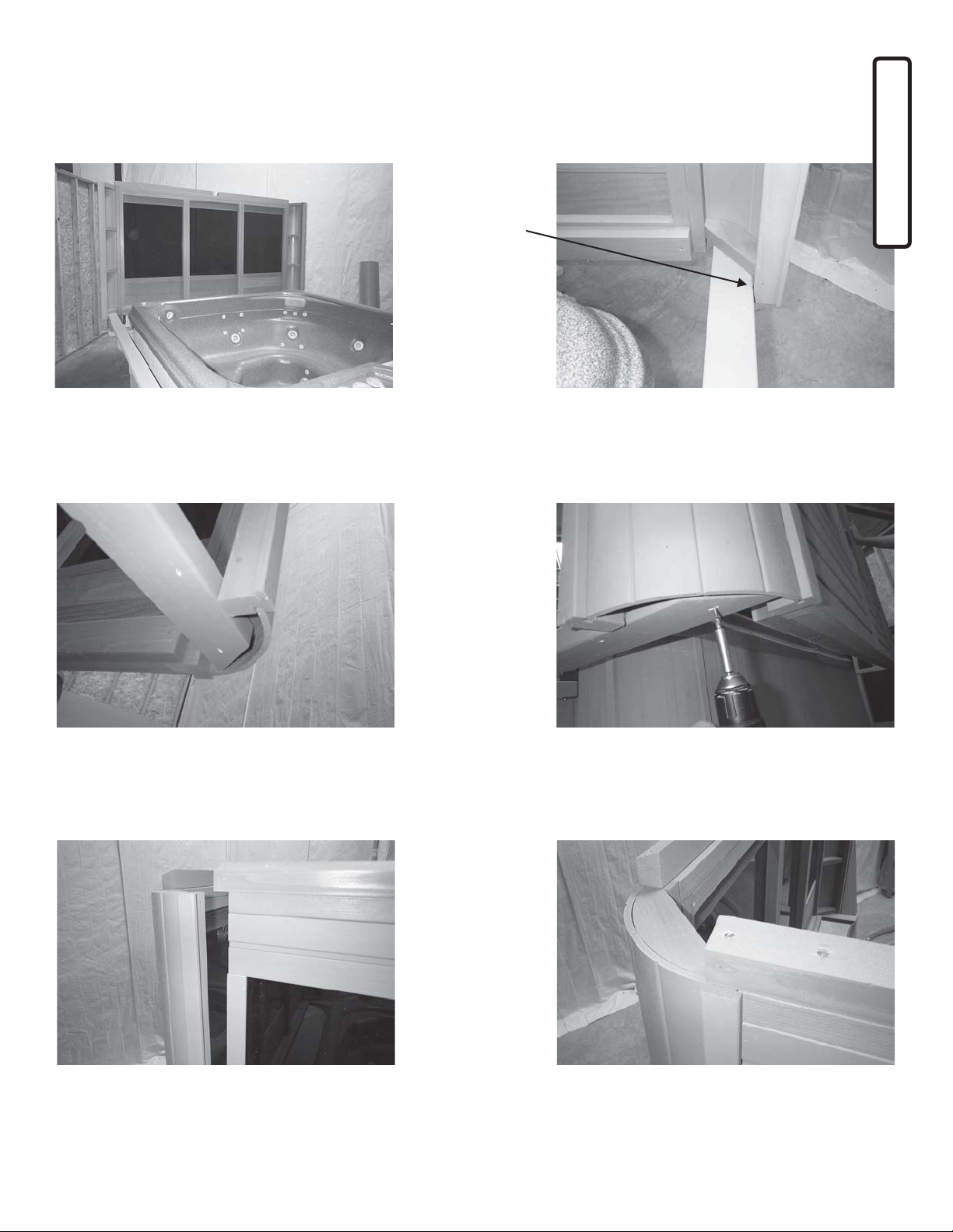
Wall panels
Set the assembled wall on top of the ends of the
shelves. The ends of the shelves fit into the hollow part
of the corner panels.
The outside edge of the shelf fits against the frame of
the corner panel. Check alignment on both shelves and
if needed, remove the screws from the brackets and
adjust the shelves.
Adjust shelf
to correct
posion.
Assemble the four walls on top of the shelves. Begin with the side opposite the spa controls (Corner mounted solid wall).
Next, install the two sides adjacent to the spa controls ( Shelf mounted door wall, or shelf mounted open wall). Last,
install the side at the spa controls (Corner mounted door wall).
Above photo shows how the shelf fits into the corner
panel.
Fasten the corner panel to the shelf from the underside
of the shelf using one 2 ½ inch screw at each corner.
Set the shelf-mounted door wall onto the shelf and
connect to the corner panel.
Connect with one 3 inch screw into the top of the frame
and three 2 ½ inch screw into the side of the frame as
done previously.

TubTop™
Sequoia Spa Shelters™ by Sequoiaworks Inc.
Wall panels
The above photo shows the two walls in place. Connect the shelves to the boom rail of the shelf-
mounted walls using 2 ½ inch screws.
Boom rail
2 ½ “ screws
The above photo shows the three walls in place. Connect the shelves to the boom rail of the shelf-
mounted walls using 2 ½ inch screws.
Fasten the two remaining corner panels to the fourth
wall.
Place the wall onto the shelves and connect to the two
walls. Adjust the posion of the shelves if necessary.
This may require removing the screws from the brack-
ets, reposioning the shelves and replacing the screws.
TubTop™
Sequoia Spa Shelters™ by Sequoiaworks Inc.
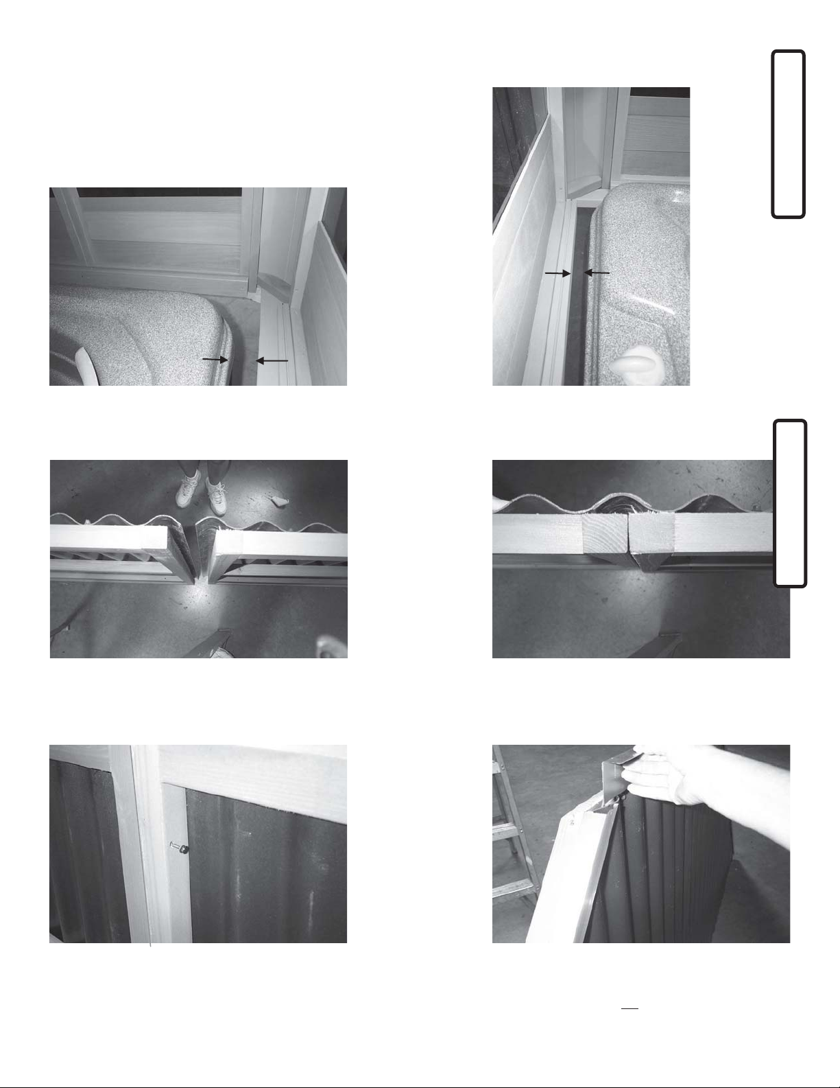
Check spacing
Check the spacing between the spa shell and the shelves and walls to
see if the space is even. There should be about 1 ½ to 2 inches of
clearance between the wall rail and the spa shell on the control side
(front). On the sides the shelves should be equal distance on both
sides. Remove screws that connect the shelves to the brackets to ad-
just if necessary.
1 ½ “
approx.
Equal to
opposite
side
Roof panels
Connect the le and right hand roof panel secons to-
gether.
The corrugaons overlap one another and the two
frames are set together.
With the frames aligned to one another, fasten the two
frames together using 2 ½ inch wood screws. (Three per
set)
Insert the flashing strip into the the C-metal trim of the
roof panel so that it is over the top surface of the corru-
gated roofing. This does not get fastened.
TubTop™
Sequoia Spa Shelters™ by Sequoiaworks Inc.
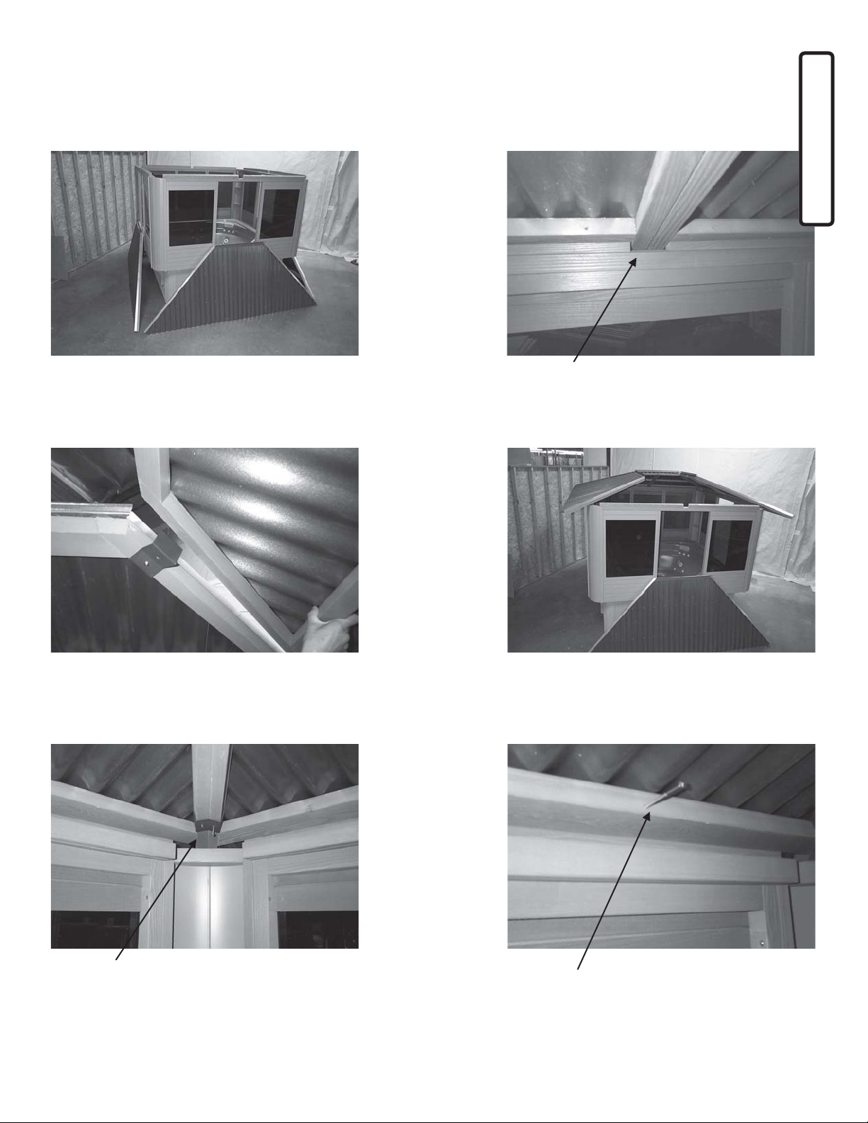
Posion the assembled roof panels around the building
in preparaon to set in place.
Place the roof panel over the top of the wall and drop
the frame into opening of the angle roof stops.
Roof panels
Connue seng the roof panels in place. Connect the
panels at the upper end where the panels meet using
the “W-brackets”. Connect these to the roof panel
frames using 1 ¼ inch pan head screws.
Installing the last roof panel may require liing the oth-
er panels slightly in order for it to drop into place. Once
in place, check that all panels are sing down on top of
the wall panels.
Add a second W-bracket at the lower end of the in-
stalled roof panels.
Connect the boom frame of the roof panel to the roof
stops of the wall panel using 3 inch wood screws.
W-bracket

TubTop™
Sequoia Spa Shelters™ by Sequoiaworks Inc.
Skylight
Fasten the aachment frame to the top of the roof pan-
els using 2 ½ inch wood screws. The frame is posioned
so that it is even with the edge of the roof frame and so
there is a 1 ¼ inch space on the right side for adjacent
frame.
Connue unl all four aachment frames are in place.
2 ½” screws Lapping frame
Place the skylight over the top of the opening and set
down onto the aachment frame. The skylight also sets
over the flashings of the roof panels. This may require
adjusng the flashing to fit under the skylight.
Photo above shows the skylight in place.
Center the skylight to the opening from the inside of the
building. The inside ledge of the skylight frame aligns to
the inside surface of the aachment frame.
The skylight is held in place using two wooden “L” mold-
ings. Fasten the molding to the aachment frame using
#6 x 1¼ inch wood screws.
Align boom edge
TubTop™
Sequoia Spa Shelters™ by Sequoiaworks Inc.
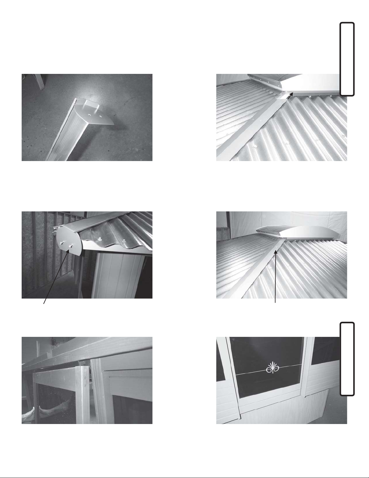
Roof trims
Door
Insert the roof cap into the slots on the end cap. Place the roof cap over the metal edge trims of the roof
panels and slide the end upward and under the skylight.
Fasten the end cap into the end of the roof panel frame
using #8 x ¾ inch pan head screws.
Fasten the roof cap to the edge trim usin #8 x ½ inch self
- drilling pan head screws.
Install the doors by sliding the plasc guide at the top of
the door into the track at the header. Li the door up
and swing the boom guide into the track at the boom.
The photo above shows the properly installed door.

TubTop™
Sequoia Spa Shelters™ by Sequoiaworks Inc.
Cover support shelf
If using the Cover support shelf, fasten the shelf on to
the back wall panel secons meet. Use 3 inch wood
screws. The top of the shelf should be even with the
top of the spa.
3”
screws
The Cover Shelf is used as a resng support for the spa cover while the spa is in use.
They are not needed if using a cover li device.
Bar top (oponal)
Aach the bar brackets to the sides of the wall opening as
shown below. Use 2 1/2 inch wood screws.
Place the bar top on to the brackets. Center the bar
top to the opening and fasten from underneath
with 2 1/2 inch wood screws.

TubTop™
Sequoia Spa Shelters™ by Sequoiaworks Inc.
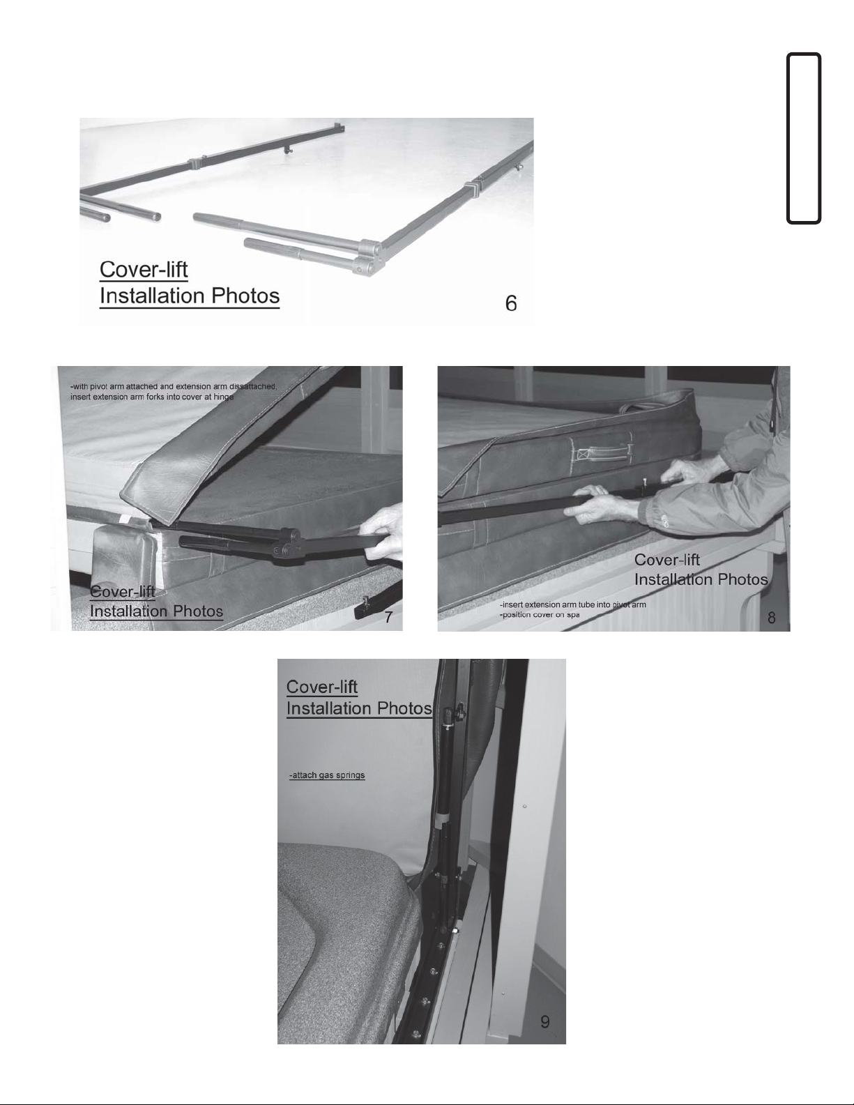
Cover Li (oponal)
If using a Cover Valet™ cover li, follow the direcons provided with the Cover Valet™ .
Use the “deck-mounted” method and aach directly to the shelves of the TubTop. If in-
stalling a bar top on the TubTop, install the Cover Valet™ first for ease of installaon. The
photos below show the basic steps of the installaon.
TubTop™
Sequoia Spa Shelters™ by Sequoiaworks Inc.
Cover Li (oponal)
This manual suits for next models
9
Table of contents
Popular Hot Tub manuals by other brands


Insignia
Insignia INS8058L installation manual

Intex
Intex PureSpa SPJ-H-22 owner's manual

Intex
Intex PureSpa SPJ-H-20-1 owner's manual

Penner Bathing Spas
Penner Bathing Spas Dream Spa Parts and service manual

Sundance Spas
Sundance Spas CAMDEN 780 owner's manual

Saratoga Spa
Saratoga Spa Pavilion owner's manual


