Spa Location
Service Access: Some people choose to install tile, stone, or
custom wood around their spas. If you are installing your spa with
custom trimming, remember to allow access for service. Should
your spa need service, a technician may need to remove the spa’s
equipment compartment door or side panels, or access the spa
from beneath. Also, it is always best to design special installations
so the spa can still be moved, or lifted from the ground.
Access to Circuit Breakers: For service purposes, allow
easy access to the circuit breakers in the electrical service panel
(permanently connected models), or to the interrupter switch on
the end of the power cord (cord-connected models).
Electrical Safety Requirements: e installation of all
spas must be in accordance with national and local wiring rules
and with applicable permits consistent with local regulations. A
licensed Electrician must perform the electrical installation and
GFCI test procedure. Each Bullfrog Spa is manufactured and
tested to a standard that provides maximum protection against
electrical shock.
Improper wiring may prevent the spa from operating safely which
could result in electrical shock, injury, or death. Improper wiring
could also lead to a malfunction of the spa’s equipment and risk
of re. When considering a location for your spa, consult with a
licensed Electrician pertaining to the following:
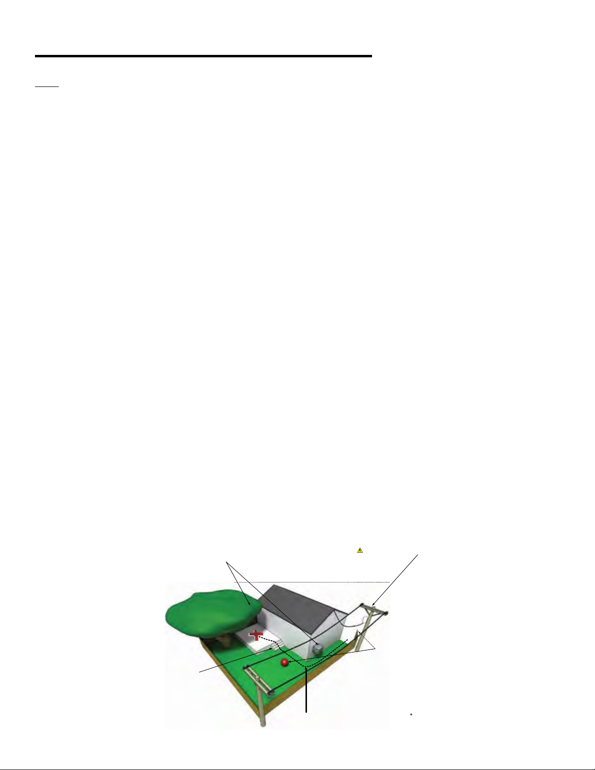
Overhead Power Lines: Based upon the national and local
wiring rules that apply to your area, you will need to install your
spa at the required minimum horizontal and vertical distances
from all power lines.
Service Disconnect: Based upon your area, a disconnect
device must be incorporated into the xed wiring in accordance
with national and local wiring rules. If the national and local
wiring rules permit, a GFCI or RCD Sub-Panel may be used
to substitute the service disconnect, providing that it is located
within the same parameters.
Electrical Outlets, Switches and Devices: Based upon
the national and local wiring rules that apply to your area, you
must install your spa at the required minimum distance from all
electrical outlets, switches, and devices.
Bonding: Based upon the national and local wiring rules that
apply to your area, the Control System Box located inside the
equipment compartment of your spa must be bonded to all metal
equipment, handrails, xtures, enclosures, pipe, or conduit that
are located within the maximum specied distances. e bonding
is to be connected to the ground lug connector on the exterior
surface of the Control System Box and all metal items previously
described.
Equipment Compartment Access: Make sure the spa is
positioned so access to the equipment compartment will not be
blocked.
All other national and local rules that may be applicable.
Water Drainage: Your spa contains an equipment
compartment, which houses all of its electrical components.
Allowing water into the equipment compartment can damage
the electronics, or may result in tripping your spa’s circuit
breaker. If installing the spa in a SpaVault, below ground level,
or where water may accumulate it is the owner’s responsibility to
ensure that water will drain adequately so as not to damage spa
equipment. For normal installations at ground level choose a site
where water will drain away from the spa.
Use of a Cover-Lifting Mechanism: If using a cover-
lifting mechanism, allow up to 18 inches (.61m) of clearance
behind the spa. Check with your authorized Bullfrog Spas
Dealer for the exact clearance requirements for the cover-lifting
mechanism.
Spa Foundation
General Guidelines: Select a structurally sound at surface
that is reasonably level to serve as your spa’s foundation. A
foundation that shifts or settles may cause stress to the spa shell.
e foundation that your spa rests on must have a weight bearing
load capability of supporting the weight of your spa, its water, and
the people using it. e maximum lled weight of a spa can be
as much as 6,000 lbs. (2,800kg), plus the weight of the occupants
that use the spa (for the weight bearing load requirements as
well as the maximum lled weight of your spa, refer to the Spa
Technical Specications Chart or contact your local authorized
Bullfrog Spas Dealer).
If your spa’s pad is slightly sloped it may not aect the
performance of the spa or its structure, however, there should
be no dips, sags, or unevenness in the pad. Most patios are
built to slope away from the house for drainage purposes. ere
should be no more than a 1/2” (1cm) slope in an 8 ft (2m) run.
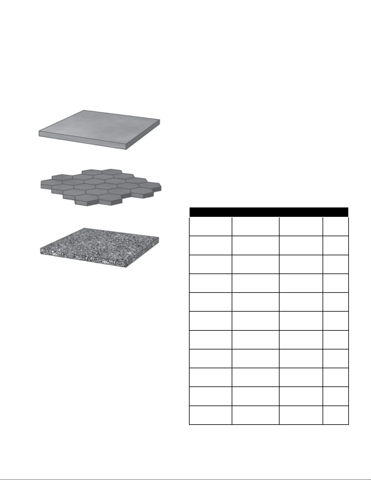
Recommended ooring materials include a concrete pad, concrete
pavers or bricks, pea gravel, or crushed rock 1.5” (4cm) or less, or
a reinforced deck. Additionally, your authorized Bullfrog Spas
Dealer may sell or recommend pre-formed spa pads.
NOTE: Concrete foundations should be a minimum of 4
inches (10cm) thick and should be reinforced with either rebar or
mesh. For electrical grounding purposes, the rebar or mesh should
be attached to a bond wire (see Electrical Requirements and
Installation Instructions).
WARNING: To prevent serious damage to your spa, it is
important that the spa foundation be supported by a at, stable,
and consistent subsurface. Bullfrog Spas International highly
recommends consulting a qualied, licensed contractor prior to
the installation of any spa foundation. For assistance, contact your
authorized Bullfrog Spas Dealer.
WARNING: Because your spa pad must provide continuous
support for the entire base of the spa, you should never level
it with shims. If it is necessary to level your spa, make sure the
entire spa’s structure is fully supported, both in the center as well
as the outer edge. When leveling your spa, there should be no
voids beneath it. Contact your authorized Bullfrog Spas Dealer
before making any leveling adjustments. Structural damage to the
spa resulting from incorrect installation, placement on an
inadequate foundation, or improper leveling will void the 2
spa’s warranty.


 owner's manual")