SEQURE SQ-A60 User manual
Thank you for using this product. Please read the instructions carefully
before use to avoid errors in operation.
A Remark,
The "warning'and'note'in the specification are defined as follows:
Warning: abuse shall result in death or serious injury.
Note: abuse shall result in damage to the users or the objects.
Please confirm the package content
Mainframe.
lnstruction manual
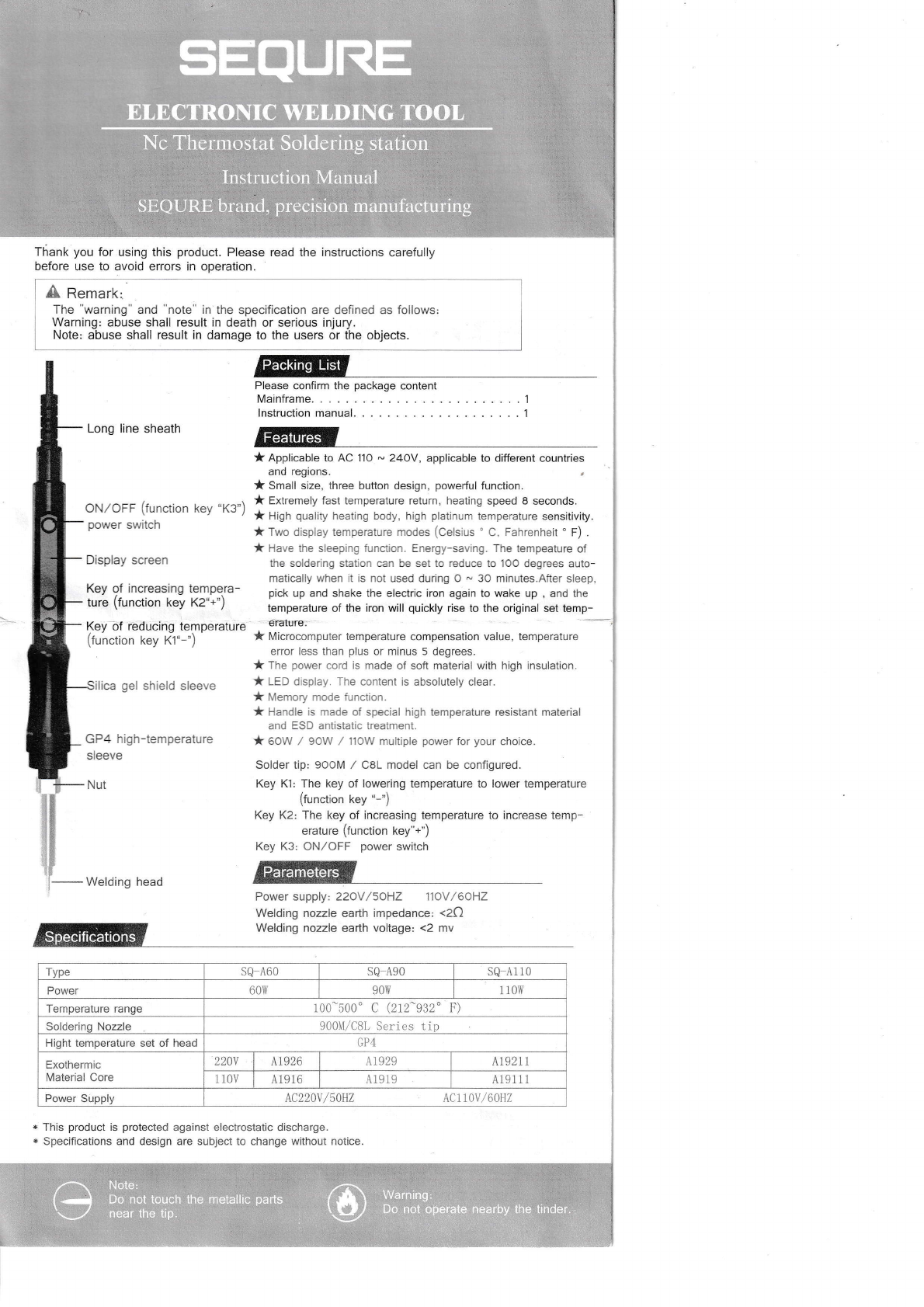
Long line sheath
ilica gel shield sleeve
GP4 high-temperature
sleeve
Nut
Welding head
* This product is protected against electrostatic discharge.
* Specifications and design are subject to change without notice.
* Applicable to AC 110 * 24OY, applicable to different countries
and regions.
* Small size, three button design, powerful function.
* Extremely fast temperature return, heating speed 8 seconds.
* High quality heating body, high platinum temperature sensitivity.
*Two display temperature modes (Celsius'C, Fahrenheit'F) .
* Have the sleeping function. Energy-saving. The tempeature of
the soldering slation can be set to reduce to lOO degrees auto-
matically when it as not used during O - 30 minutes.After sleep,
pick up and shake the electric iron again to wake up , and the
temperature of the iron will quickly rise to the original sel temp-
' €raturs
* Microcomputer temperature compensation value, temperature
error less than plus or minus 5 degrees.
* The power cord is made of soft material with high insulation.
* LED display. The content is absolutely clear.
* Memory mode function.
* Handle is made of special high temperature resistant material
and ESD antistatic treatment.
* oow / gow / ]1ow multiple power for your choice.
Solder tip: gOoM / C8L model can be configured.
Key K1: The key of lowering temperature to lower temperature
(function tey "-")
Key K2: The key of increasing temperature to increase temp-
erature (function key"+")
Key K3: ON,/OFF power switch
Power supply: 22oV/soHZ 11oV/6oHZ
Welding nozzle earth impedance: <2C)
Welding nozzle earth voltage: <2 mv
ON,/OFF (function key "K3")
power switch
Display screen
Key of increasing tempera-
ture (function key Kz"+')
Key bf reducing temperature
(function key K1"-")
Features
Type SQ_A6O SQ A9O sQ A110
Power 60\ry 90\{ 1 10\{
Temperature range 100-500' c (212-932" F)
Solderinq Nozzle 900M/C8L Series tip
Hight temperature set of head GP4
Exothermic
Material Core 220v A1926 A1929 A19211
1 10V A19 16 A1919 A191 1 1
Power Supply LC220v /s\HZ Actl1v /60H2
SEQUtil=
ELECTRONIC WELDING. IOOL
,Nc Therm:stat Soldering: qtltion
lnstruction Manual
SEauRtri|ryand, precision manufacturing
Teackits L'"t /
Note:
Do not touch the metallic parts
near'ihd.'ti[.. .,':' :'-" Do.not ,epefale, lEarby ,tfle. tinder

A cnurtont
Because abuse will cause burns and fire.
Please strictly comply with the following matters;
a Please avoid abusing the soldering iron, should operate according to the working
instruction.
aDo not touch the metal parts of the soldering iron.
a Do not use the soldering iron nearby the combustible.
a Notice staffs that the soldering nozzle is easy to cause burn or other dangerous accidents, so
please turn off the powei after getting off work.
oBefore replace soldering nozzle, please confirm the power is shut off and the nozzle is cool.
a lt is strictly prohibited to use the product when any damage, especially the power cord damages.
o This product uses three lines ground-plug which must insert the three hole socket. Prohibit
changing the plug or using not ground-plug adapter which results bad ground connection. lf
want to extend wire, please use the three lines ground- power cord.
aPlease don't knock the soldering iron on the table to clear the residual tin slag on iron. Because
thus doing shall result in serious damage to the soldering iron.
aPlease don't replace the solder iron without authorization.
o lt is suggested that replace parts with the original accessories.
a Don't get the solder iron wet. Please do not use or take apart the solder iron and pull the cord
a lt is suggested to work in good ventilation environment, or providing small fans by yourselves
owing to the soldering iron will produce smoke when soldering.
a Prohibit making any damage to body or objects when use the soldering iron.
oChildren don't know the danger of solder iron, so this product should be placed where children
are not easy contact or used and storage where providing admitted supervision.
Use numerical control constant temperature welding table
I . Boot Operation
1. Power-on. Please remember to use groundi
2. Turn on power switch of main machine: ON
ll . Setup Function
Display'F and 'C.
Long press K2 key to enter the setting item:
Short fress K1 key tb enter settings. Shorlpress the K1 key in turn, and display the conversion
between'C and'F. After setting, release the key. Press the KI and K2 keys at tha-same.time--
to save the settings and exit the settings.
)fl'r'a oo*"r. switch (function key K3)
+
Press K1 key
2. Temperature Setting
Long press K2 key, enter the setting item, then continue to short press K2 key to traverse the setting
item, enter the temperature setting item:
Short press K'1 key to enter the setting, short press Kl key to set the temperature of -1 degree. And long
press Kl key, the setting temperature will continue to decrease rapidly during the press of the key; short
press K2 key to set the temperature of +1 degree, long press K2 key, the setting temperature will continue
to increase rapidly during the press of the key. When the preset temperature value is reached, release the
key. Press the K1 and K2 keys at the same time to save the settings and exit the settings.
ffitffiffi'c
ElInffi "p ,mlm,f7'e
mmm.;
mmnb
HNEI'r
3. Compensation Temperature Setting
Long press K2 key to enter the setting item, then continue to press K2 key to traverse the setting
item, enter the compensation temperature setting item:
Short press K'l key to enter the setting, short press Kl key to set the compensation temperature -1
degree, Iong press Kl key to set the compensation temperature to decrease continuously during the
press of the key; short press K2 key to set the compensation temperature +1 degree, long press
K2 key to set the compensation temperature to increase continuously during the press of the key.
When the preset temperature value is reached, release the key. Press the Kl and K2 keys at the
same time to save the settings and exit the seftings.
Operational Guidelines
I
will be saved
I
*,Atteisiittin';statrst l'ieott!,ithitaunay]islitinS witl be saved automatically and exit.
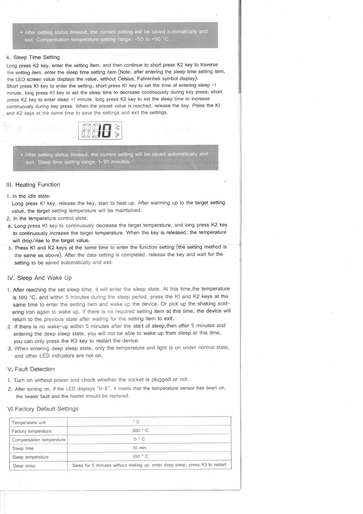
4. Sleep Time Setting
Long press K2key, enter the setting item, and then continue to short press K2 key to traverse
the setting item, enter the sleep time setting item (Note' after entering the sleep time setting item,
the LED screen value displays the value, without celsius, Fahrenheit symbol display),
Short press Kl key to enter the setting, short press K1 key to set the time of entering sleep -1
minute, long press Kl key to set the sleep time lo decrease continuously during key press; short
press K2 key to enter sleep +'1 minute, long press K2 key to set the sleep time to increase
continuously during key press. When the preset value is reached, release the key. Press the Kl
and K2 keys at the same time to save the settings and exit the settings.
nfrfr e
[]trlfJ'p
lll. Heating Function
1. ln the idle state:
Long press Kl key, release the key, start to heat up. After warming up to the target setting
value, the target setting temperature will be maintained.
2. ln the temperature control state:
a. Long press Kl key to continuously decrease the target temperature, and long press K2 key
to continuously increase the target temperature. When the key is released, the temperature
will drop,/rise to the target value.
b. Press K1 and K2 keys ai the same time to enter ihe function setting (the setting method
the same as above). After the data setting is completed, release the key and wait for the
setting to be saved automatically and exit.
lV. Sleep And Wake Up
'1. After reaching the set sleep time, it will enter the sleep state. At this time,the temperature
is IOO "C, and within 5 minutes during the sleep period, press the Kl and K2 keys at the
same time to enter the setting item and wake up the device. Or pick up the shaking sold-
ering iron again to wake up. lf there is no required setting item at this time, the device will
return to the previous state after waiting for the setting item to exit.
2. lf there is no wake-up within 5 minutes after the start of sleep,then after 5 minutes and
entering the deep sleep state, you will not be able to wake up from sleep at this time,
you can only press the K3 key to restart the device.
3. When entering deep sleep state, only the temperature unit light is on under normal state,
and other LED indicators are not on.
V. Fault Detection
1. Turn on without power and check whether the socket is plugged or not.
2. After turning on, if the LED displays "H-E", it meets that the temperature sensor has been on,
the heater fault and the heater should be replaced.
Vl.Factory Default Settings
Temperature unit C
Factory temperature 300 'c
Compensation temperature o"c
Sleep time 10 min
Sleep temperature 100 'c
Deep sleep Sleep for 5 minutes without waking up, enter deep sleep, press K3 to restart
* After setting status timeout, the current seuing will be saved automatically and
exit. Compensa:ion temperature setting range: -5O to +5o 'C.
* After.setting glatus tirneou!,rthe.currell:gqlti.ng:'illl be'Saygddu1omq.licql.li,r and
exk.s,leeptime,sgtiirrg'rbrige,,t.id,'*iihule5.;.,:''--''1"'lr.iii":'.11 -',1:
Welding Nozzle
1. Welding nozzle using:
Too high temperature will weaken the welding nozzle function, so choose the temperature as low
as possible. The welding nozzle of restoring force is good, even under the low temperature it can
also fully complete the welding work. Whar is more, it can protect temperature sensitive elements
2. Do not use welding nozzle,
When do not use welding nozzle, do not let welding nozzle in high temperature condition for long
time. Or you will make the flux of welding nozzle on change to oxide. which will make the heat
conduction of welding nozzle weaker.
3. After use welding nozzle:
After the use, should wipe clean the welding nozzle and plate new tin layer on it to prevent the
welding nozzle from oxidation.
4. Elding nozzle maintain
Check and clean the welding nozzle:
a. Connect the power supply. wait for the temperature to stab llze.
b.After the temperature stabllity. clean the welding nozzle with cleaning sponge. and check rt.
c. lf welding nozzle on tin part contains black oxide. plate a new tin layer on the welding nozzle,
then use leaning sponge to wipe welding nozzle. So repettive operatron to Temove the oxide
and then plate a new tin layer on the welding nozzle.
d. lf welding nozzle becomes deformation or serious erosion. must replace the weldrng nozzle with
a new one (Suggest using the o'iginal nozzle).
5. Welding nozzle cleaning:
Should periodically clean the weld nozzle with the cleaning sponge (or with a cleaning wet
cloth). Because after welding, the residual slag will produce oxide and carbide which can
damage the welding nozzle or cause welding error or make the heat conduction of welding
nozzle weaker. Long time continuously using welding nozzle, once a week thewelding nozzle
should be taken apart to clean the residual slag on the surface, so to prevent welding nozzle
damaged and reduce temperature.
6. Extend the welding nozzle life,
a. After each finish the welding work, plate a new tin layer on the welding nozzle to prevent
welding nozzle from oxidatron and extend the using life.
b. Under the condition of normal working please set the temperature as low as possible. Low
temperature can reduce welding nozzle oxidation, as well as can easily to weld components.
c. Only in necessary condition to use thin welding nozzle, because of the thin welding nozzle less
durable than the coarse one.
d. Don't use welding nozzle as detection tools, because weldrng nozzle bending will make coating
rupture and shorten its service life.
e. Use less active rosin flux, because the high content of active rosin will accelerate welding nozzle
coating corrosion.
f. When not using welding nozzle, please tum off it' s power as far as possible to prolong its
service life.
g. Don't butt welding nozzle with great heavy stress, because that is not equal to faster heat.
Heating core
Type 60w 90w 110W
r10v A1916 A19i9 419111
220V A1926 41929 A19211
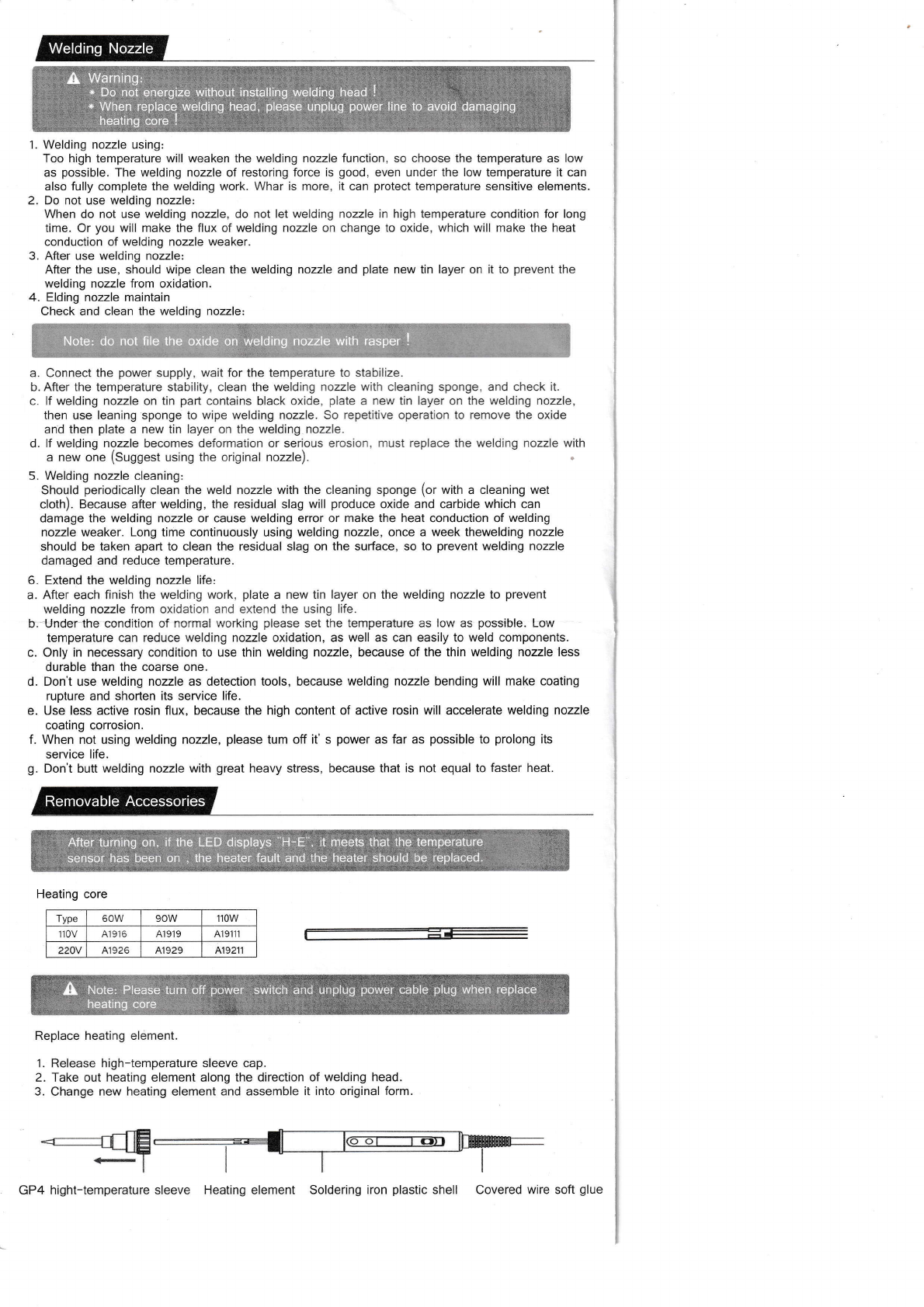
Replace heating element.
'1. Release high-temperature sleeve cap.
2. Take out heating element along the direction of welding head.
3. Change new heating element and assemble it into original form
Removable Accessories
$, Nore cable.
heati &x
p'ug when
ng core ialet,lu
K
GP4 hight-temperature sleeve Heating element Soldering iron plastic shell Covered wire soft glue
Note: do not file the oxide oii welding nozzle with rasper !
Afteiturning on, if the LED displays ; iil,rleei5. that the :teirperature
sensor htas been on . lhe healdr fault: and the:healer:shquld be replaced.
Please power

9OOM / CeL Freelead special soldering-tip Unit: mm
900l{l-T Bs00[-T-0. 5c
@;-
900[f-T-8a2 -
t00t -T-LB 900fi-T-0. 8C
6t:=
9C0M-r-S 5900M-t*t e
@Orts
900M-T-r cF'
900M-T-34
A
\v
900x-T-0. 8D
(9
lt
OB
900it*T-1. 5cr
5O;P
900H-T-2C
I
900it-T-2cr'
9001r-T- t. 2D 900t -T-3c
000fi"T-3cF'
6.*fl
*1,, 1@rr
900tt-T*1. 0D 900!r-T-s1 0
6 ;*,
J! I!,, I@rtr
900rr-T-2. 4D 900$-T-4C
@
*eF @:
900Ir-T-4CF
., Ii I
-r-
gffi-I-S11
@'F
900M-T-S 3900[4-T- 1
@'f
IL @
s00t -T-s I
@
g$il-T-zLS
@
It
I
@=tr
+
esfl-T{.elb' 900t{-r-R@q
**"-ffi **-'*buqffi
U6L.U.btJ
c8L-2.43
c8L-1 .08
c8L-2.08
Theoutsidediameter: @6. 5mm
c8L-1.68
e8L-1.8C
@
15
):--]
8
f(
L(l*
t)
@
C8L-1.OBC
@
C8L-2.OBC
o
c8L-4.0C
ejfr

,!F*l ffi *fEl ffi
6+W 6fz--rEl
J_I__-.d gl . .,+-|---. $i
0.6,,
-it-
I
c8L-2.4D
c8L-1.2D
c8L-1.6D
C8L-KL
06 ,,
6
CBL.4,OD
c8L-1.2D
c8t--K
C8L-KR
@
?.4 ll
6
c8L-3.03C
c8L-5.2D
c8L-3.?r
C8L-KF
,14
H ffi l----- -t-ut 11-
t@)J-1 bL7ttr.-<
'+l---T- E-=f-
--..-fl.-
@l,.L
@ffi rot#*
wrx
r.s l,l
,Jrl
I
0.5 t,
r.s.ld- i
@
I o.s
*d*
(0 a
Item No, Part No Part Name Specifications
csQ19M1A-J-001 Heating core o3.9*60MM
@5Q19M1A-PCBA PCBA Board 128*15.8*1.0MM
osQ19M1A-J-003 Cladding iron clamp Surface plating
@sQi 9M1A-J-002 lron head shell components Plastic + metal plating
@5Q1 9M 1 A-S-002 Soldering iron plastic shell Translucent
@sQ19M1A-S-001 Covered wire soft glue Covered wire soft glue
@so19M1A-5-003 Silica gel sheath Silica gel 023.4"451\4M
@sQ19M 1A-S-00s Button 1Silica gel {D6"4.65MM
@sQ19M1A-S-00s Button 2Silica gel 06"4.65MM
@SQ19M1A-S OO4 Button 3Silica gel 04.85"5.6MM
7p.,*t* I
This manual suits for next models
2
Other SEQURE Soldering Gun manuals


