Sera 620.10 User manual

Diaphragm Relief Valve
Operating Instructions
TA
48
Rev.
13
en
05/2016
Subject to technical modifications!
www.sera-web.com
1
Product: Diaphragm relief valve
Type: 620.10
622.10
623.10
624.10
625.10
626.10
627.10
Please state here the exact type and serial
number of your diaphragm relief valve.
(can be read off the type plate on the diaphragm relief valve)
Type:
Serial No.:
These data are important in case of queries or for ordering
spare- and wearing parts and must absolutely be stated.
Manufacturer:
sera GmbH
sera-Straße 1
34376 Immenhausen
Germany
Tel.: +49 5673 999-00
Fax.: +49 5673 999-01
www.sera-web.com
Translation of the original operating instructions!

Diaphragm Relief Valve
Operating Instructions
2
www.sera-web.com
Subject to technical modifications!
TA
48
Rev.
13
en
05/2016
Table of contents
1General...................................................................3
2Types......................................................................3
2.1 Type plate...............................................................3
2.2 Materials.................................................................4
3Safety instructions ..................................................4
3.1 Quality instructions / purpose..................................4
3.2 Marking of notes.....................................................4
3.2.1 Marking of notes in these operating instructions............4
3.2.2 Marking of notes on the product.....................................4
3.3 Dangers in case of inobservance of the safety
instructions .............................................................4
3.4 Safety conscious working........................................4
3.5 Intended use...........................................................5
3.6 Approved installation-, maintenance
and operating personnel .........................................5
3.7 Personal protection for maintenance and service....5
4Areas of application and function............................6
5Test / identification..................................................6
6Checking the packaging at the place
of destination ..........................................................6
7Storage...................................................................6
8Technical specifications..........................................7
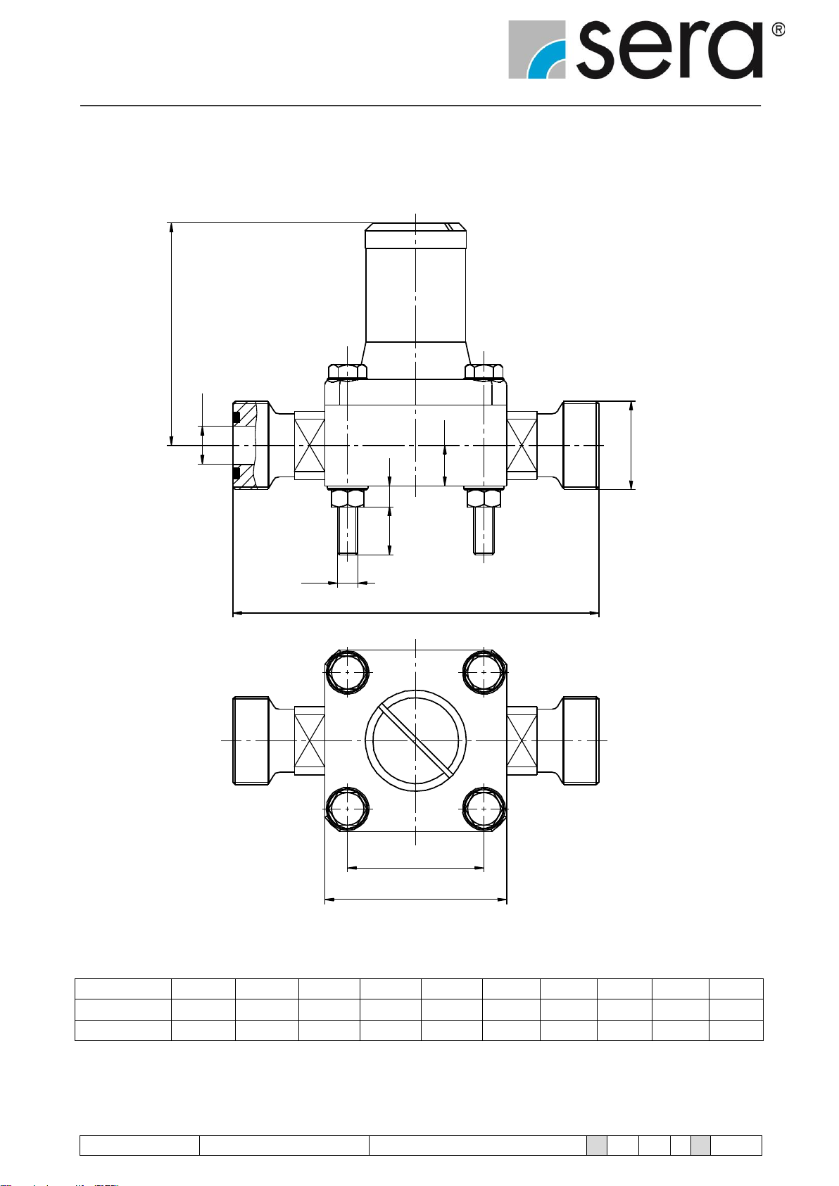
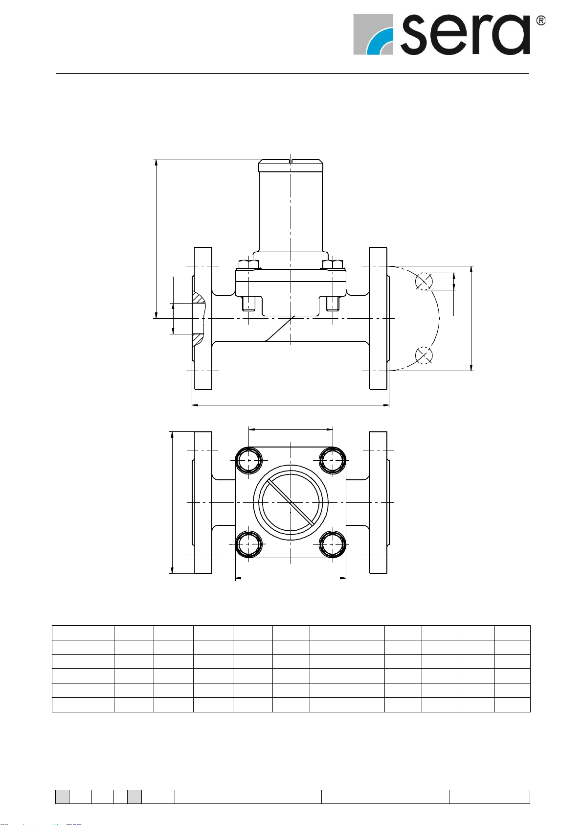
8.1 Dimensions of the diaphragm relief valve................7
8.1.1 PP-, PVC-, PVDF-, PP-GFK-, PVDF-GFK-design.........7
8.1.2 1.4581-design.................................................................8
8.1.3 GG-, GG-rubber-coated, 1.4581-design ........................9
8.2 Technical specifications........................................ 10
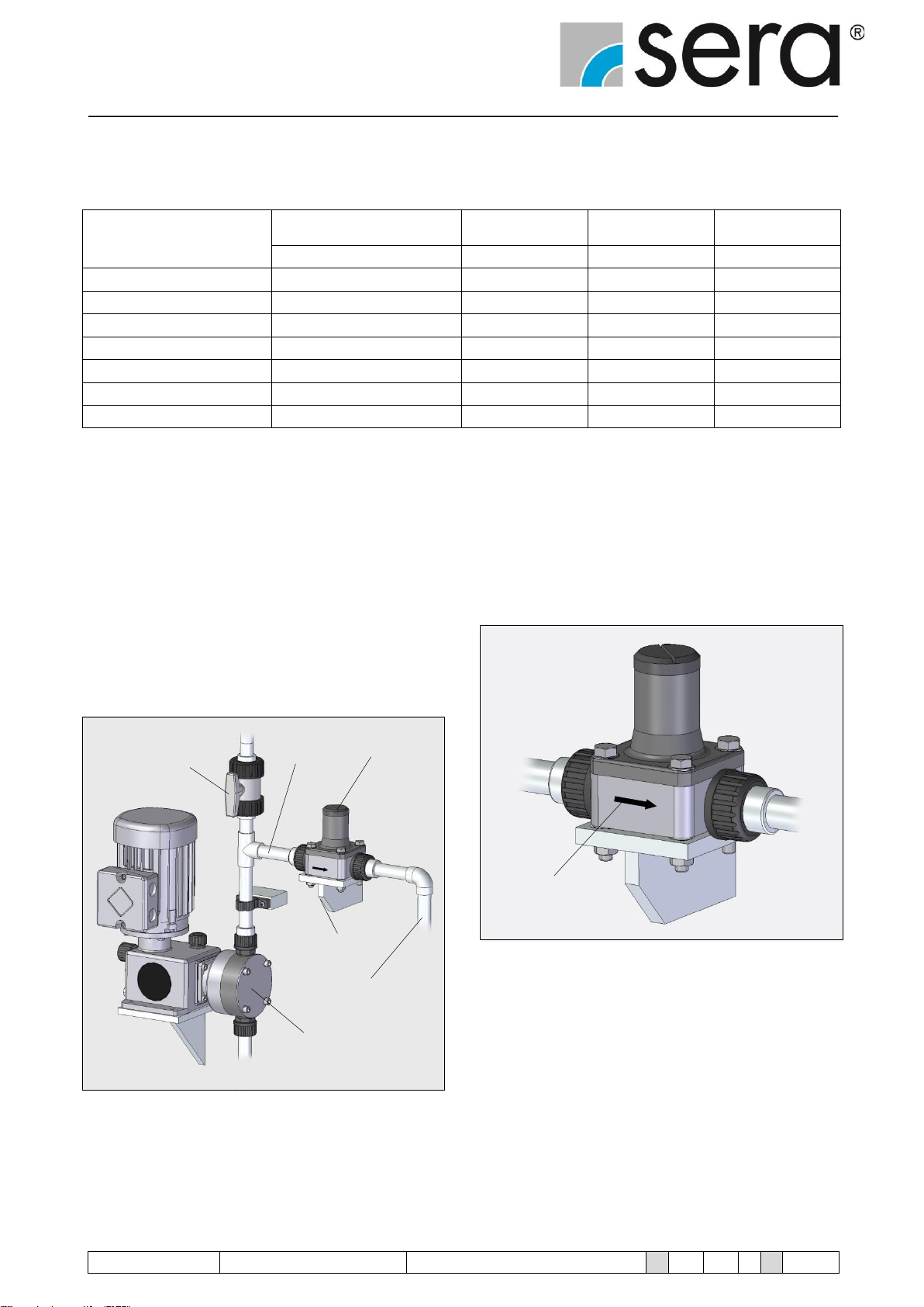
9Installation ............................................................10
9.1 Supply line............................................................ 11
9.2 Return line............................................................ 11
10 Start-up.................................................................11
11 Adjustment............................................................12
12 Operation in explosion-hazardous areas...............12
13 Spare- and wearing parts......................................12
13.1 Spare- and wearing parts kit .................................13
14 Changing the diaphragm.......................................15
14.1 General.................................................................15
14.2 Changing the diaphragm.......................................15
15 Shut-down.............................................................16
16 Disposal................................................................16
16.1 Dismantling and transport......................................16
16.2 Complete disposal.................................................16
17 Clearance Certificate.............................................17

Diaphragm Relief Valve
Operating Instructions
TA
48
Rev.
13
en
05/2016
Subject to technical modifications!
www.sera-web.com
3
1 General
Before commissioning and during operation of the sera dia-
phragm relief valve the respective regulations valid at the place
of installation are to be observed.
sera diaphragm relief valves are delivered ready for assembly.
Carefully read these instructions and especially the safety in-
structions herein contained before installation and initial start-
up of the valves.
The sera diaphragm relief valve protects the pump, fittings,
and pipes from unacceptable overpressure.
2 Types
2.1 Type plate
Each sera diaphragm relief valve is factory provided with a
type plate. The following information can be found on this type
plate.
1 2 3 4 5 6
Fig. 01 Type plate
Explanation of the indications on the type
plate
1
Pe
Set pressure:
The set pressure corresponds to the
overpressure (at the valve inlet) at
which the valve opens under test condi-
tions (atmospheric pressure at the valve
outlet).
2
Mat.
Materials:
Material specifications for housing / dia-
phragm according to DIN/ISO
3
Type
Diaphragm relief valve type
4
No.
Serial number of the diaphragm relief
valve
5
DN
Nominal width:
The nominal width is a characteristic
parameter which is used for pipes and
parts, e.g. tubes, tube connections, fit-
tings etc. matching each other.
Nominal widths correspond to the pipe
diameter in mm.
6
PN
Nominal pressure:
The nominal pressure is the permissible
operating pressure in bar at 20° C.
Table 01 Explanation of type plate

Diaphragm Relief Valve
Operating Instructions
4
www.sera-web.com
Subject to technical modifications!
TA
48
Rev.
13
en
05/2016
2.2 Materials
The materials used are stated in the order confirmation.
3 Safety instructions
3.1 Quality instructions / purpose
Please read these operating instructions carefully before the
diaphragm relief valve is started or serviced. Observance of
these operating instructions and, in particular, the safety in-
structions, helps to
•avoid dangers to persons, machines, and environment
•increase reliability and service life of the diaphragm relief
valve and the complete system
•reduce repair cost and downtime.
The sera quality management and quality assurance system
for pumps, systems, and fittings is certified according to
ISO 9001:2008.
sera products comply with the valid safety requiremens and
accident prevention regulations.
CAUTION !
Always keep these operating instructions within reach at
the place of installation.
CAUTION !
Pay attention to the safety data sheet of the pumped me-
dium! The owner must take corresponding accident pre-
vention measures to protect operating personnel from
danger through the pumped media used!
3.2 Marking of notes
3.2.1 Marking of notes in these operating
instructions
Special notes in these operating instructions are marked with
the general danger symbol
(safety symbol in compliance with DIN 4844 –W9)
3.2.2 Marking of notes on the product
Symbols which are directly attached to the diaphragm relief
valve, e.g. symbols for flow direction, are to be observed and
kept in legible condition.
3.3 Dangers in case of inobservance of the
safety instructions
Inobservance of these safety instructions can result in danger
to persons, hazards to the environment and damage to the
diaphragm relief valve.
Inobservance can result in:
•Failure of important functions of the diaphragm relief
valve/system
•Inobservance of prescribed methods for maintenance and
servicing
•Danger to persons through chemical influences
•Hazards to the environment through leaking dangerous
media
3.4 Safety conscious working
The safety instructions specified in these operating instruc-
tions, the national regulations concerning accident prevention
as well as internal working-, operating-, and safety instructions
of the owner are to be observed.

Diaphragm Relief Valve
Operating Instructions
TA
48
Rev.
13
en
05/2016
Subject to technical modifications!
www.sera-web.com
5
3.5 Intended use
sera diaphragm relief valves are only to be deployed according
to the intended purpose stated in the order confirmation.
sera does not assume any responsibility for damage resulting
from an operation which does not conform with the intended
use.
If the diaphragm relief valve is to be used for other applica-
tions, then the suitability of the valve for the new operating
conditions must be discussed with sera beforehand!
Criteria for proper operation of the diaphragm relief valve:
•Max. operating pressure of the diaphragm relief valve
•Observe characteristics of the pumped medium (please
see safety- and product data sheet of the pumped medi-
um –the safety data sheet is to be provided by the sup-
plier of the chemical)
•Resistance of the materials which come in contact with
the pumped medium
•Operating conditions at the place of installation
•Temperature of the pumped medium
sera does not assume any responsibility if these criteria are
not or only partly observed by the owner / operator.
CAUTION !
The structural design of the diaphragm relief valve must
not be changed!
3.6 Approved installation-, maintenance and
operating personnel
The system operator may only approve persons to operate or
maintain the unit, who are at least eighteen years old and suit-
ably qualified, and of a physical and mental state to perform
the tasks entrusted to them. These persons must be properly
instructed and act responsibly, properly and reliably. The oper-
ating personnel must be familiar with all applicable accident
prevention and safety instructions and regulations.
3.7 Personal protection for maintenance and
service
In order to avoid risks to health, the provisions of the German
Ordinance on Hazardous Substances (GefStoffV) (§14 Safety
Data Sheet) and relevant national safety regulations for the
pumped medium and the operating conditions of the dia-
phragm relief valves must strictly be adhered to.
CAUTION !
Wear protective clothing, gloves, and a face protecting
mask.
CAUTION !
Personal protective equipment must be provided by the
owner!

Diaphragm Relief Valve
Operating Instructions
6
www.sera-web.com
Subject to technical modifications!
TA
48
Rev.
13
en
05/2016
4 Areas of application and function
sera diaphragm relief valves can be used for liquid media
without solid matters but exclusively for the intended use as
specified by the manufacturer.
sera diaphragm relief valves protect especially oscillating dis-
placement pumps which, in theory, can build up a infinitely
high pressure. If pressure lines are restricted or closed the
pressure may reach a multiple of the permissible system pres-
sure, e.g. owing to clogged lines (foreign matters, crystals) or
closed shut-off valves, clogged nozzles or filters etc.
CAUTION !
As sera diaphragm relief valves cannot reduce accelera-
tion pressure peaks with oscillating displacement pumps
an additional pulsation damper is to be provided.
CAUTION !
sera diaphragm relief valves are no safety valves as per
the requirements of the regulations for pressure systems
2014/68/EU.
CAUTION !
Do not change the setting of the relief valve!
5 Test / identification
sera diaphragm relief valves are tested in our works and set to
an operative pressure.
The set pressure corresponds to the technical delivery condi-
tions which are indicated on the type plate (see Fig.
01/02/Table 01).
Lid
Seal
Cover
Type plate
Fig. 02
6 Checking the packaging at the place of
destination
On delivery, immediately check the packaging for damage.
Report any external damage immediately to the transport
company, and fill out a damage report. After the transport
company has recorded the damage, open the package and
check the contents for damage.
7 Storage
An undamaged packaging protects the unit during subsequent
storage and should only be opened when the diaphragm relief
valve is installed.
Proper storage increases the service life of the diaphragm re-
lief valve and comprises prevention of negative influences
such as heat, humidity, dust, chemicals etc.
The following storage instructions are to be observed:
•Storage place: cool, dry, dust-free and slightly ventilated
•Storage temperatures between -10°C and +45°C
•Relative air humidity not more than 50%.
If these values are exceeded, metal products should be sealed
in foil and protected from condensation water with a suitable
desiccant.
Do not store solvents, fuels, lubricants, chemicals, acids, disin-
fectants and similar in the storage room.

Diaphragm Relief Valve
Operating Instructions
TA
48
Rev.
13
en
05/2016
Subject to technical modifications!
www.sera-web.com
7
H
p
i
L1 g
DN
q A
q B G
n
DN
L2 g
p
i
n
q A
q B O k
O d
H
O D
s
8 Technical specifications
8.1 Dimensions of the diaphragm relief valve
8.1.1 PP-, PVC-, PVDF-, PP-GFK-, PVDF-GFK-design
Connection: Thread pipe connection Connection: Loose flange
Fig. 03 Dimensions
Type
DN
G
A
B
H
L1
n
g 1)
i 1)
p 1)
L2
D
k
s
d
PP
PVC
620.10
8
G ¾
50
38
80
80
13
M5
15
5
110
90
60
12
10
14
622.10
15
G 1
72
54
90
115
15
M8
17
8
145
95
65
12
11
14
623.10
20
G 1 ¼
80
60
116
130
28
M8
17
8
160
105
75
12
12
14
624.10
25
G 1 ½
90
68
123
160
22,5
M10
11
10
175
115
85
16
14
14
625.10
32
G 2
100
76
157
180
24
M10
15
10
200
140
100
16
15
18
626.10
40
G 2 ¼
115
87
180
235
30
M12
26
13
235
150
110
20
16
18
627.10
50
G 2 ¾
140
106
185
260
38
M12
18
13
260
165
125
20
18
18
Table 02 Dimensions
1) Fixture for mounting the valve on brackets etc.

Diaphragm Relief Valve
Operating Instructions
8
www.sera-web.com
Subject to technical modifications!
TA
48
Rev.
13
en
05/2016
L
g
DN
n
H
p
i
G
qB
qA
8.1.2 1.4581-design
Connection: Thread pipe connection
Fig. 04 Dimensions
Type
DN
G
A
B
H
L
n
g 1)
i 1)
p 1)
620.10
8
G ¾
50
38
80
110
13
M5
10
5
622.10
15
G 1
72
54
88
145
16
M8
17
8
Table 03 Dimensions
1) Fixture for mounting the valve on brackets etc.

Diaphragm Relief Valve
Operating Instructions
TA
48
Rev.
13
en
05/2016
Subject to technical modifications!
www.sera-web.com
9
L
DN
O D
H
O l
O k
q B
q A
8.1.3 GG-, GG-rubber-coated, 1.4581-design
Connecting dimensions according to DIN 2501, PN 10 / ANSI 150 lbs/sq in
Fig. 05 Dimensions
Type
DN
A
B
H
L
D 1)
D 2)
k 1)
k 2)
l 1)
l 2)
623.10
20
80
60
125
150
105
99
75
70
14
16
624.10
25
90
68
130
160
115
108
85
79
14
16
625.10
32
100
76
165
180
140
118
100
89
18
16
626.10
40
115
87
180
200
150
127
110
98
18
16
627.10
50
140
106
185
230
165
153
125
121
18
19
Table 04 Dimensions
1) Connecting dimensions according to DIN 2501
2) Connecting dimensions ANSI150

Diaphragm Relief Valve
Operating Instructions
10
www.sera-web.com
Subject to technical modifications!
TA
48
Rev.
13
en
05/2016
8.2 Technical specifications
Type
Max. allowable operating
pressure
Set pressure pe
Max. capacity Q
KVS value
[bar]
[bar]
l/h
m3/h
620.10
10
2,5 ... 10
200
0,26
622.10
10
2,5 ... 10
500
0,6
623.10
10
1,5 ... 10
1000
1,12
624.10
10
1,5 ... 10
2000
2,1
625.10
10
1,5 ... 10
4000
4,0
626.10
10
1,5 ... 10
7000
6,7
627.10
10
1,5 ... 10
10000
9,12
Table 05 Technical data
9 Installation
•The cover is to be mounted vertically to the top.
•The diaphragm relief valve is to be installed in such a way
that no static, dynamic or thermal loads from the supply-
or return line are transmitted to the relief valve.
•Install the diaphragm relief valve near the pump and in
front of the first shut-off valve.
Diaphragm
Supply line relief valve
Shut-off valve
Bracket
Return line
Dosing pump
Fig. 06 Example of an installation
•The flow direction is indicated by an arrow.
Flow direction
Fig. 07

Diaphragm Relief Valve
Operating Instructions
TA
48
Rev.
13
en
05/2016
Subject to technical modifications!
www.sera-web.com
11
9.1 Supply line
Keep the supply line as short as possible and lay it in such a
way that only low acceleration pressures or pressure losses
develop.
Avoid contamination and precipitations.
9.2 Return line
Keep the return line as short as possible and lay it downgrade.
Elbows are to be preferred to angles. The return line must not
be under pressure, provide for a free outlet (see Fig. 06).
Make sure that there are no shut-off valves or check valves in
the return line.
If the return line is linked to the suction line of the pump, no
check valves may be installed in the suction line.
Lay the lines in such a way that precipitations are excluded.
10 Start-up
During commissioning, observe the following:
•Open all shut-off valves that are mounted in the suction
line and pressure line (except for flushing and discharge
fittings).
•Start pump / system.
•Slowly increase the delivery rate via the stroke frequency
or stroke length adjustment to the maximum setting (see
Fig. 08).
Dosing pump
Stroke length
adjustment
Fig. 08
The diaphragm closes the inlet channel by the pressure spring
initial tension (= set pressure of the valve in bar).
If the medium at the diaphragm reaches the set pressure, the
diaphragm is lifted and the medium flows in the outlet channel
(see Fig. 09).
Diaphragm Damping fluid
Inlet channel Outlet channel
Fig. 09 Operational mode
The diaphragm closes the inlet channel only when the pres-
sure of the medium drops below the set pressure (see Fig. 10).
Lid
Set screw
Diaphragm Damping fluid
Inlet channel Outlet channel
Fig. 10 Operational mode
CAUTION !
The use of damping fluid is shown of the table 07
(page 16).

Diaphragm Relief Valve
Operating Instructions
12
www.sera-web.com
Subject to technical modifications!
TA
48
Rev.
13
en
05/2016
11 Adjustment
Check the set pressure by means of e.g. a pipe test pump. If
the set pressure does not match the indication on the type
plate, remove lid and correct pressure using the set screw.
•Turning counterclockwise: the set pressure reduces
•Turning clockwise: the set pressure increases
Pipe test pump Diaphragm
relief valve
Fig.11 Check
CAUTION !
The operator is obliged to document these checks.
CAUTION !
Never screw in the set screw to a depth so that the
spring(s) is (are) compressed to solid length!
CAUTION !
–diaphragm relief valves are factory-set to the set
pressure stated in the order confirmation. A sealing wax
seal is located on the transition piece between lid and
cover.
12 Operation in explosion-hazardous areas
As there are no ignition sources the relief valves can be used
unproblematically in the hazardous area (ATEX) acc. to
2014/34/EU.
The relief valves have to be integrated into the equipotential
bonding by customer.
13 Spare- and wearing parts
Depending on their use and period of use, wearing parts must
be replaced at regular intervals in order to ensure a safe func-
tion of the diaphragm relief valve.
The diaphragm should be replaced:
Every 3000 hours, at least once a year.
In case of a premature diaphragm rupture caused by hard op-
erating conditions, switch off the diaphragm relief valve and
replace the diaphragm (see Chapter 13).

Diaphragm Relief Valve
Operating Instructions
TA
48
Rev.
13
en
05/2016
Subject to technical modifications!
www.sera-web.com
13
13.1 Spare- and wearing parts kit
Fig. 12 Spare- and wearing parts kit
2
3
4
5
9
7
8
10
11
12
13
14
15
16
17
18
19
23
20
21
22

Diaphragm Relief Valve
Operating Instructions
14
www.sera-web.com
Subject to technical modifications!
TA
48
Rev.
13
en
05/2016
Spare- and wearing parts kit
Valve body kit (plastic,
connection: thread pipe connection)
Item
Designation
1
Hexagon screws
2
Disks
3
Lid
4
O-ring
6
Cover
11
O-rings
12
Disks
13
Nuts
14
Valve body
Valve body kit (plastic,
connection: loose flange)
Item
Designation
1
Hexagon screws
2
Disks
3
Lid
4
O-ring
6
Cover
15
O-rings
16
Valve body
17
Disks
18
Nuts
Valve body kit (1.4581)
Item
Designation
1
Hexagon screws
2
Disks
3
Lid
4
O-ring
6
Cover
19
O-rings
20
Valve body
21
Disks
22
Nuts
Valve body kit (GG, GG-rubber-coated, 1.4581)
Item
Designation
1
Hexagon screws
2
Disks
3
Lid
4
O-ring
6
Cover
23
Valve body
Diaphragm kit
Item
Designation
5
Set screw
7
Pressure spring
8
Pressure spring
9
Pressure disk
10
Diaphragm
10.1
Damping fluid
CAUTION !
The use of damping fluid is shown of the table 07
(page 16).

Diaphragm Relief Valve
Operating Instructions
TA
48
Rev.
13
en
05/2016
Subject to technical modifications!
www.sera-web.com
15
14 Changing the diaphragm
14.1 General
In case of maintenance- and repair work on the diaphragm
relief valve the safety- and warning notes in Chapter 3 are to
be observed.
Pay attention to all instructions concerning the handling of the
pumped medium when the diaphragm relief valve is opened.
Observe the EC safety data sheets!
CAUTION !
The diaphragm may only be replaced by authorized and
qualified personnel.
14.2 Changing the diaphragm
•Unscrew the lid
•Measure dimension “T” of the set screw with a caliper
gauge and document in Table 06.
T
Upper edge
- Cover
- Set screw
Fig. 13 Setting
Type
Dimension "T“ (mm)
620.10
622.10
623.10
624.10
625.10
626.10
627.10
Table 06
•Unscrew the set screw
•Remove pressure spring(s)
•Unscrew screws
•Remove cover on the valve body
•Diaphragm is now freely accessible and can be replaced
Lid
O-ring
Set screw
Cover
Pressure springs
Pressure disk
Diaphragm
Valve body
Flow direction
Fig. 14 Diaphragm replacement

Diaphragm Relief Valve
Operating Instructions
16
www.sera-web.com
Subject to technical modifications!
TA
48
Rev.
13
en
05/2016
Assemble the pump in reversed order
•Insert diaphragm (PTFE-foil pointing downstream) in the
recess of the cover.
•Fasten cover with screws on the valve housing.
•Fill in damping fluid (for type and quantity please see
Table 07).
Damping
fluid
Pressure disk
Diaphragm
Fig. 15
Type
Damping fluid
Quantity
[ml]
620.10
Glycerine
DAB 87
excluding
622.10
excluding
623.10
excluding
624.10
excluding
625.10
36
626.10
56
627.10
138
Table 07 Damping fluid
•Insert pressure spring.
•Screw in set screw up to dimension “T”.
•Screw lid in cover.
15 Shut-down
•Shut-down the pump/system and secure it against restart-
ing!
•Make sure that all pipes with diaphragm relief valves are
depressurized!
•Drain the diaphragm relief valve and the connected pipes
using drain valves!
•Remove residues of the pumped medium out of the dia-
phragm relief valve by rinsing it with a compatible deter-
gent!
•The diaphragm relief valve damper can then be removed
out of the pipe.
16 Disposal
Shut-down system. Please see “Shut-down”.
16.1 Dismantling and transport
•Remove all fluid residues, clean thoroughly, neutralize
and decontaminate.
•Package unit and ship.
16.2 Complete disposal
•Remove all fluid residues from unit.
•Drain off lubricants and dispose of according to regula-
tions!
•Dismount materials and send them to a suitable waste
disposal company!
CAUTION !
The consignor is responsible for damage caused by leak-
ing lubricants and fluids!

Diaphragm Relief Valve
Operating Instructions
TA
48
Rev.
13
en
05/2016
Subject to technical modifications!
www.sera-web.com
17
17 Clearance Certificate
NOTE!
Inspection / repair of machines and machine parts is only
carried out after the opposite clearance certificate was
filled in correctly and completely by authorized and quali-
fied personnel.
NOTE!
Acceptance will be refused if parts are returned to the
manufacturer without a proper clearance certificate.
All industrial companies are obligated by the legal provisions
for occupational health, e.g. the workplaces ordinances, the
Ordinance on Hazardous Substances, the regulations for pre-
vention of accidents and the environmental protection regula-
tions such as the Waste Management Act and the German
Household Water Act to protect their employees or man and
the environment from detrimental effects when handling haz-
ardous substances.
Should special safety precautions be necessary despite careful
draining and cleaning of the product the necessary information
are to be provided.
Machines which are operated with radioactive media shall only
be inspected and/or repaired in the safety
area of the owner by a sera specialized fitter.
The clearance certificate is part of the inspection-/repair order.
sera reserves the right to refuse acceptance of the order for
other reasons.
NOTE!
Please make a copy and leave the original with the operat-
ing instructions!
(can also be downloaded from: www.sera-web.com)

Diaphragm Relief Valve
Operating Instructions
18
www.sera-web.com
Subject to technical modifications!
TA
48
Rev.
13
en
05/2016

Diaphragm Relief Valve
Operating Instructions
TA
48
Rev.
13
en
05/2016
Subject to technical modifications!
www.sera-web.com
19
Notes

Diaphragm Relief Valve
Operating Instructions
20
www.sera-web.com
Subject to technical modifications!
TA
48
Rev.
13
en
05/2016
This manual suits for next models
6
Table of contents
Other Sera Control Unit manuals
Popular Control Unit manuals by other brands

Siemens
Siemens LMV52 series user manual

Beninca
Beninca MBE operating instructions

CLA-VAL
CLA-VAL 58-01 Installation, operation and maintenance

Abexo
Abexo 051D user manual

National Instruments
National Instruments SCC-DO01 user guide

Farris Engineering
Farris Engineering 2600 Series General Installation and Maintenance Instructions