Sercel VE432 DPG Installation and operating manual

VE432 DPG
Installation
& Reference
MANUAL
Documentation No. 0311385 Issue : April 1999
Software version 3.0

In no event shall SERCEL be liable for incidental or consequential
damages or related expenses resulting from the use of this product, or
arising out of or related to this manual or the information contained in it,
even if SERCEL has been advised, or knew or should have known of the
possibility of such damages.
The information in this manual is believed to be accurate and reliable.
However, SERCEL reserves the right to make changes to its products or
specifications at any time, without notice, in order to improve design or
performance and to supply the best possible product.

0311385 Issue : April 1999
i
Table Of Contents
INTRODUCTION--------------------------------------------------------------------------------------------------1-1
GENERAL DESCRIPTION------------------------------------------------------------------------------------1-1
SPECIFICATIONS-----------------------------------------------------------------------------------------------1-5
UNPACKING-------------------------------------------------------------------------------------------------------1-6
CONNECTING A DPG------------------------------------------------------------------------------------------2-1
DPG MOUNTING DIMENSIONS-----------------------------------------------------------------------------2-1
DPG STANDARD CONNECTIONS-------------------------------------------------------------------------2-2
1 APM, 1 DPG CONFIGURATION-------------------------------------------------------------------------------2-4
2 OR 3 APMS, 1 DPG CONFIGURATION----------------------------------------------------------------------2-5
CONFIGURATIONS WITH UP TO 8 APMS AND UP TO 4 DPGS--------------------------------------------2-6
CONNECTING A HUSKY TERMINAL TO A DPG--------------------------------------------------------------2-9
DPG MASTER/SLAVE CONFIGURATION---------------------------------------------------------------------2-10
OUTPUT SIGNAL SPECIFICATIONS--------------------------------------------------------------------2-14
RECORDER CABLE--------------------------------------------------------------------------------------------2-16
ANALOG PILOT CABLE---------------------------------------------------------------------------------------2-17
RADIO CABLE----------------------------------------------------------------------------------------------------2-18
DPG CONNECTORS------------------------------------------------------------------------------------------2-19
SOFTWARE INSTALLATION --------------------------------------------------------------------------------3-1
SOLARIS INSTALLATION OR RE-INSTALLATION ----------------------------------------------3-1
YEAR 2000 PATCH---------------------------------------------------------------------------------------------3-7
VE432 STANDALONE INSTALLATION-------------------------------------------------------------------3-8
VE432 SOFTWARE INSTALLATION FOR USE WITH SN388-------------------------------------3-8
GETTING STARTED--------------------------------------------------------------------------------------------3-9
CUSTOM SWEEPS----------------------------------------------------------------------------------------------4-1
ABOUT CUSTOM SWEEPS----------------------------------------------------------------------------------------4-1
LOADING A CUSTOM SWEEP FILE TO A DPG-----------------------------------------------------------------4-2

0311385 Issue : April 1999
ii
USING VE432 WITH A RECORDING SYSTEM OTHER THAN SERCEL-----------------------5-1
CONNECTION DIAGRAM-------------------------------------------------------------------------------------------5-1
DISTINCTIONS TO BE MADE --------------------------------------------------------------------------------------5-2
TOOLSVEHCI SOFTWARE LOADING UTILITY--------------------------------------------------------6-1
LOADING SOFTWARE TO A DPG OR DSD--------------------------------------------------------------------6-1
GROUND VISCOSITY AND STIFFNESS -----------------------------------------------------------------7-1
CONVERSION TO NORMALIZED UNITS ----------------------------------------------------------------7-1
VE432 STATUS --------------------------------------------------------------------------------------------------8-1
DPG ------------------------------------------------------------------------------------------------------------------8-1
DSD ------------------------------------------------------------------------------------------------------------------8-1

INTRODUCTION
GENERAL DESCRIPTION
0311385 Issue : April 1999
1-1
INTRODUCTION
GENERAL DESCRIPTION
General
The VE 432 is a new generation of Vibrator Digital Control System, using a fully auto-
adaptive servomechanism. It enables the use of all advanced Vibroseis techniques
such as :
- pseudo-random sweeps
- multiple simultaneous sources in flip-flop or slip-modes
- coded sweeps
- cascaded (*) sweeps
The VE 432 is fully compatible with most satellite DGPS and Glonass receivers, for
integrated tracking of source positions.
DPG DSD
(*) (Exxon Patent)

INTRODUCTION
GENERAL DESCRIPTION
0311385 Issue : April 1999
1-2
Digital Pilot Generator (DPG)
The DPG is connected to the data acquisition system through an Ethernet link and
acts as a master control unit for the VE 432 system.
The DPG can be :
-fully integrated with the SN 388 acquisition system,
-or connected to any other type of acquisition system, using its own graphic
user interface.
-or used as Slave unit to control acquisition start on a remote (slave)
acquisition system.
Digital Servo Drive (DSD)
Installed in each vibrator, the DSD performs real time control of the vibrator ground
force, computes and transmits a complete attribute set for a QC data base.
Maintenance modes are available that make it possible to easily check the
performance of the vibrator hardware and the GPS system.
VE432 Main features
•• Signal generation
Up to 4 different simultaneous pilot signals are generated by the DPG.
A pilot or a sweep signal is generated from an operator-defined library of 32 basic
signals combined with up/down, phase shift parameters.
Basic signals are defined by their frequency range, frequency vs. time law, time
duration, tapers and amplitude vs. time law.
A single DPG can handle up to 4 vibrator fleets with a total of 28 vibrators.
•• Digital vibrator control
By an automatic identification procedure, the VE432 digital model is adapted to any
type of vibrator without the need for manual adjustment.
The fully digital auto-adaptive servomechanism performs an optimal control which
minimizes the phase and distortion and maximizes the fundamental output.
Optimal digital control allows :
-fast sweep rate,
-combination of sweep segments with no dead time, used in cascaded (*)
-pseudo-random sweeps, for environmentally friendly vibration,
unlimited variety of user-defined sweeps (custom sweep type).
Exxon Patent

INTRODUCTION
GENERAL DESCRIPTION
0311385 Issue : April 1999
1-3
•• Enhanced real-time Quality Control
The DSD integrates a complete set of functions for automatic sensor tests. The check
for coherence between all the measurements contributes to quality assurance,
ensuring that the vibrator generates the proper sweep, without any risk of polarity
inversion.
A complete QC data base is generated for real-time or post-processing analysis
including :
- phase
- distortion
- fundamental ground force
In addition, the digital control identifies the ground viscosity and stiffness, which
regularly provides information on the ground absorption model and can be used to
enhance seismic data.
Real-time phase, distortion, fundamental ground force values versus time or
frequency, for each vibrator and each sweep, are available on request.
•• Bar-graph QC display
All the QC information is displayed within color bar-graphs with automatic threshold
detection. For each vibrator, current values and average values over the last 50
vibrations are shown.
•• Complete graphic display
In addition to the QC data base information, the VE 432 has the capability to
graphically display in real time, the Phase, Distortion and Force results vs. Time or
Frequency, for each vibrator.
•• QC Statistics
On request, statistics on QC data base can be performed, for daily or longer time
period analysis, to detect any drift in vibrator performance or to be used as a
preventive maintenance tool.
•• Slip-Sweep* capability
With a recording system from SERCEL, there is no need to wait until a sweep is
complete to start the next one. (* The Slip-sweep technique, developed by PDO,
allows substantial production increase to be achieved).

INTRODUCTION
GENERAL DESCRIPTION
0311385 Issue : April 1999
1-4
•• Recording system’s automatic start of acquisition
With a recording system from SERCEL, acquisition by the recording system can be
automatically started as soon as the vibrators are ready, using the DSD Ready signal
via radio.
DSD Network:
This feature allows the SN388 system to automatically start acquisition as
soon as all vibrators in a fleet are ready (with their pads down). There are no
delays to be adjusted any more. Everything is automatically started at
maximum speed.
Fleet navigation:
With the fleet navigation option, associated with the DSD Network option, the
geographical location of the fleet is relayed to the SN388 system, which
selects the corresponding VP (shot point) from its operation table and shoots
it automatically. VPs can be shot in any order by any fleet.
The navigation option is also supported in slip-sweep mode, allowing
acquisition to start as soon as any fleet is ready at any VP.
Fleet location feedback in Positioning window
When the shot sequence is controlled by the geographical location of the
fleet on the acquisition system, the fleet location is displayed in the
Positioning window before acquisition is launched. (With no DSD network,
the fleet location displayed is the location of the "leader" vibrator).

INTRODUCTION
SPECIFICATIONS
0311385 Issue : April 1999
1-5
SPECIFICATIONS
Signal length :up to 64 s in 1-s steps.
Frequency vs. time law :linear, logarithmic, pseudo-random, Tn, Pulse, user-
defined.
Frequency range :1 to 250 Hz in 1-Hz steps.
Amplitude vs time law :linear interpolation.
Tapers :up to 1/2 signal length, Blackman Law.
Max. Number of Vibrators :28.
“T0accuracy” :±20 µs typical.
Clock accuracy :1 ppm within temperature range and per year.
QC data base format Positioning data SPS file.
QC attributes APS file.
PHYSICAL (including mounting parts)
Size (W × D × H) Weight
DPG 255 × 389 × 411 mm 10 kg
DSD 278 × 443 × 421.5 mm 18 kg
Temperature range :Operating: 0°C to 45°C.
Storage : -40°C to 70°C.
Power supply :DPG : 110 V or 220 VAC / 40 W.
DSD : 10.5 to 28 VDC / 42 W without LIFT system
(add about 50 W with Lift system ON).

INTRODUCTION
UNPACKING
0311385 Issue : April 1999
1-6
UNPACKING
The VE432 system is composed of one or more of the following pieces of equipment
(depending on the configuration to be implemented):
- Digital Pilot Generator: DPG.
- Accessory set.
- Digital Servo Drive: DSD (See DSD Installation manual).
The VE432 DPG is composed of:
oa DPG unit (1717075017) including:
-a DVP board (1717074848)
-an SAPG board (1717074645)
-a DIO board (1717074678)
oa DPG Installation and Reference Manual (0311385)
oa DSD Installation and Reference Manual (0311378)
oan accessory kit (1717075235) including:
- a VE432DSD-E GROUND CABLE (1716075996)
- a VE432DPG-E RADIO CABLE (1717075948)
- a VE432DPG-E RECORDER CABLE (1717075949)
- a VE432DPG-E ANALOG PILOT CABLE (1717075950)
- a VE432 ETHERNET BNC/BNC CABLE (1717076385)
- an ATA & TRUE IDE MODE PC board (3120077)
- an R404011 coaxial load (3530117)
- a coaxial T adapter (5050210)
- a 50 OHM coaxial cord, 5 m long (5050212)
- two black banana plugs (5110051)
- ten 5X20 fuses, 2.5 A (5330119)
- a power cord, 2.5 m long (6050039)
- an RJ45 cable, 5 m long (6050047)

INTRODUCTION
UNPACKING
0311385 Issue : April 1999
1-7
The accessory set (1718075433) is composed of
-a CCU388 software package (1A11072510)
-a palmtop computer case (747076405)
-a HUSKY palmtop computer (317076033)
-a Husky/DSD cable (1718076053)
-a Husky/DSD extension cable (1718076123)
-a red banana jack (5110011)
-a black banana jack (5110065).

INTRODUCTION
UNPACKING
0311385 Issue : April 1999
1-8

CONNECTING A DPG
DPG MOUNTING DIMENSIONS
0311385 Issue : April 1999
2-1
CONNECTING A DPG
DPG MOUNTING DIMENSIONS
Approx. 20
All dimensions in mm

CONNECTING A DPG
DPG STANDARD CONNECTIONS
0311385 Issue : April 1999
2-2
DPG STANDARD CONNECTIONS
GROUND
wing nut
COM 1
(to palmtop computer)
ANALOG PILOTS
RETURN SWEEP
RETURN PILOT
TB
PILOT 2
PILOT 1
ETHERNET
RECORDER
(to recording system)
COM 2
Radio Fuse
AC
power
HI. LINE
CONNECTING A DPG
DPG STANDARD CONNECTIONS
0311385 Issue : April 1999
2-3
FO :Start order from recording system (either contact closure or voltage
pulse). Not used with the SN388 system (the FO is sent via the
LAN).
RDYOUT :Use only with SN388 system.
CLK :Use only with SN388 system to synchronize both systems (via
SN388 Master/Slave connector).
The palmtop computer is connected to the DPG to set up the output radio level or to
load a new software release to the DPG.
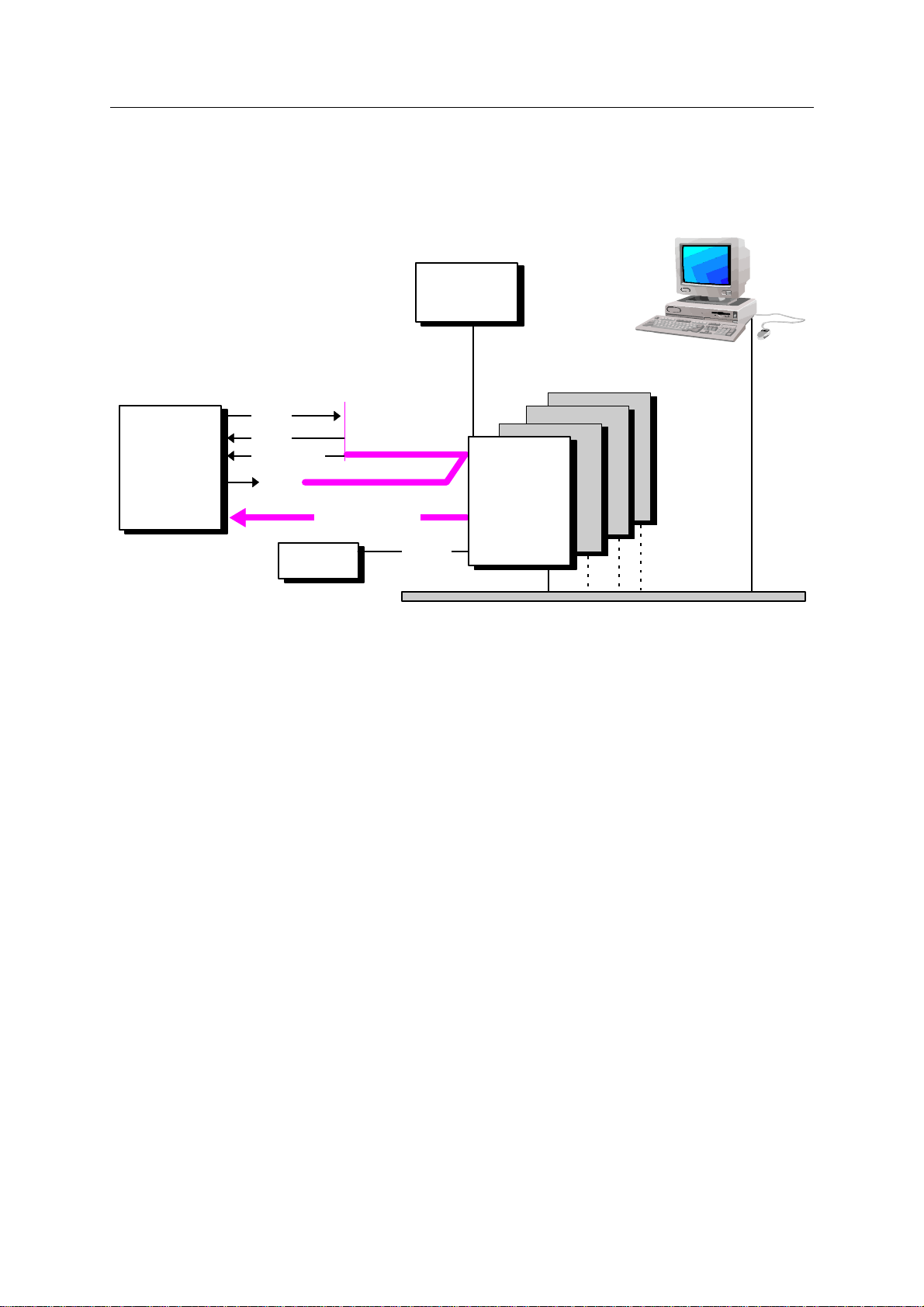
STANDARD CONNECTION DIAGRAM
TB
Ethernet
Palmtop
computer
Recording
System
Radio
(Up to 4 DPGs)
Analog Pilots
Radio
(Recorder)
VE432
DPG
CLK
(See examples
of possible
configurations
on next pages)
HCI
FO
RDYOUT
CONNECTING A DPG
1 APM, 1 DPG configuration
0311385 Issue : April 1999
2-4
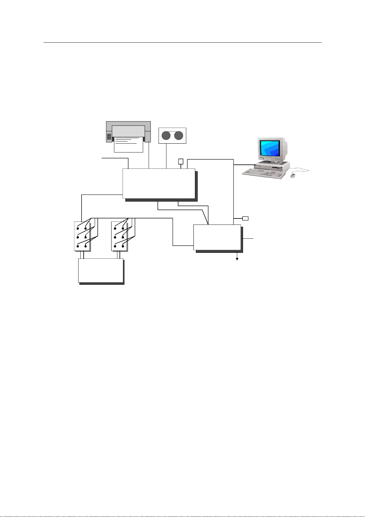
1 APM, 1 DPG configuration
READ CAMERA LAN
SN 388 APM
M / S
AUX
SU6
ACCB
POWER
(110/220 V)
SQC-Pro
CAMERA
DPG
RECORDER
ANALOG
Pilots RADIO
LAN
BLASTER
SCSI
HCI
50 Ω
50 Ω
ACCB
to RADIO
POWER
Analog Pilots: PILOTS 1 to 4 + Return Pilot + Return Sweep
(1)
(2)
(1) RECORDER cable (part No. 1717075949)
(2) ANALOG PILOT cable (part No. 1717075950)
CONNECTING A DPG
2 or 3 APMs, 1 DPG configuration
0311385 Issue : April 1999
2-5
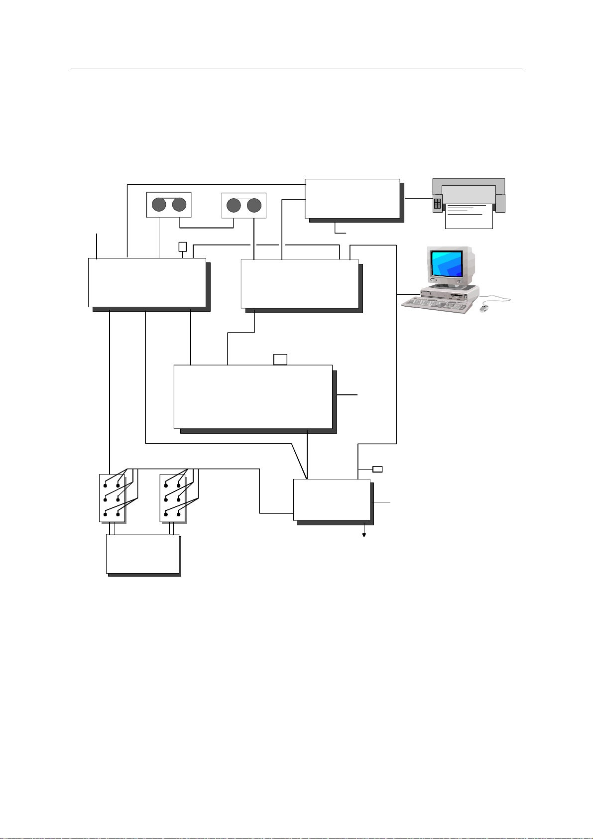
2 or 3 APMs, 1 DPG configuration
READ CAMERA LAN
APM1 (master)
M / SAUX
CAMERA
SCSI
APM2 (slave)
M / S AUX
MMCI4
IN
IN
IN
OUT
POWER
(12 VDC)
SQC-Pro
POWER (+12 V)
CAMERA
M/S
BLASTER
M/S
MMI-4
M/S
BLASTER
LAN
SCSI HCI
50 Ω
SU6
ACCB
POWER
(110/220 V)
DPG
RECORDER
ANALOG
Pilots RADIO
LAN
ACCB
to RADIO
POWER
Analog Pilots: PILOTS 1 to 4 + Return Pilot + Return Sweep
M/S
M/S terminator
(use this connector to connect
a third APM if required)
(1) RECORDER cable (part No. 1717075949)
(2) ANALOG PILOT cable (part No. 1717075950)
(3) M/S cable (part No. 1A13071930B)
(1)
(2)
(3) (3)

CONNECTING A DPG
Configurations with up to 8 APMs and up to 4 DPGs
0311385 Issue : April 1999
2-6
Configurations with up to 8 APMs and up to 4 DPGs
READ CAMERA LAN
APM1 (master)
M / SAUX
CAMERA
SCSI
APM2 (slave)
M / S AUX
MMCI4
IN
IN
IN
OUT
SU6
ACCB
ACCB
POWER
(110/220 V)
SQC-Pro
POWER (+12 V)
CAMERA
DPG1
RECORDER
ANALOG
Pilots RADIO
LAN DPG2
RECORDER
ANALOG
Pilots RADIO
LAN DPG3
RECORDER
ANALOG
Pilots RADIO
LAN
(6)
M/S8
(6)
M/S7
(6)
M/S6
(6)
M/S5
(6)
M/S4
(1) (6)
M/S3
BLASTER
M/S2
MMI-8
M/S1
BLASTER
BLASTER
(1)(3)
LAN
SCSI HCI
50 Ω
AUX1 AUX2 AUX3 DPG1 DPG2 DPG3 DPG4
(4) (4) (4)
50 Ω
ACCB
(2) (2) (2)
SU6
to RADIO 1 to RADIO 2 to RADIO 3
Part No.
(1) M/S cable 1A13071930B
(2) MMI-8 ACCB cable 1A13077600A
(3) APM BLASTER MMI-8 cable 1A13077599A
(4) DPG RECORDER MMI-8 cable 1A13077598A
(5) ANALOG PILOTS cable see VE432 DPG kit
(6) 14-19 plugs, M/S terminator 1A13072560
(with A wired to S, J wired to K)
(1), (2), (3), (4), and (6) contained in
Slip-Sweep option 1717077328B
(5) (5) (5)
This configuration should be used to connect either 4 or more APMs and 1 DPG, or
up to 8 APMs and up to 4 DPGs (Slip-sweep configuration).
Two pilots for each DPG are connected to the AUX line via ACCB interfaces. More
ACCB boxes can be used if more auxiliary channels need to be recorded.

CONNECTING A DPG
Configurations with up to 8 APMs and up to 4 DPGs
0311385 Issue : April 1999
2-7
Description of the links between the different modules
(when using an MMI-8 box)
(1) M/S cable (14-19S / 14-19S)
Used to connect the APM modules together. A plug with pin A wired to S, and J wired
to K (M/S terminator) needs to be connected to any unused M/S MMI-8 connector on
the MMI-8 box.
The TB signal on pins G and H is a logic OR of the TB signals from all the DPGs
connected.
(2) MMI-8 ACCB cable between MMI-8 and auxiliary line via ACCB box
(12-3S / banana plugs)
MMI-8
A, B TB connections from DPGs to AUX line
(A is wired to the red banana plug and B to the black one).
(3) APM BLASTER MMI-8 cable (16-26S / 12-10S)
MMI-8 BLASTER
C, D READY from DPGs to master APM via MMI-8. R, S
This signal is a logic “AND” of all connected DPGs, used to tell
the SN388 that VE432 is ready (used in normal mode only).
A, B FO from master APM (not used with VE432). A, B
G, H READY_IN from APM to DPG (not used). G, H
(4) DPG RECORDER MMI-8 cable between DPG and MMI-8 (14-19S / 12-14S)
RECORDER MMI-8
A, BCLOCK (from 17.920 MHz MMI-8 oscillator) A, B
all APMs and DPGs use the same clock from MMI_8 oscillator.
F, G READY from DPG to master APM via MMI-8 box F, G
(see APM BLASTER cable, C, D).
K, L TB from DPGnto AUXn(used in slip-sweep mode) and to master APM K, L
BLASTER plug (used in normal mode).
M, N FO from master APM (not used with VE432, this signal is sent by APM M, N
via the LAN in normal and slip-sweep modes).
P, R READY_IN from master APM to DPG (not used). P, R
The system will run in slip-sweep mode when the Slip-sweep option is enabled in the
OPERATION window, with the Continuous mode selected.

CONNECTING A DPG
Configurations with up to 8 APMs and up to 4 DPGs
0311385 Issue : April 1999
2-8
The sweeps then start automatically as soon as the vibrators are ready and a minimum
delay has elapsed after the start of the previous sweep. This minimum time is
“Slip time” + 2 s (when using 2 T0 parameters in the DPG radio transmission).
If no message is sent by the vibrators, the sweep starts at the end of a programmable
“Slip window” delay after the end of the previous sweep. Setting this delay to 99 s
amounts to setting an infinite delay (no start).
T: 0.5 s + FO-TB time (≈1.5 s with 2 T0 data) ≈2 s
Slip time
Slip time
Slip time
Slip time
Slip window
T
T
T
Fleet 1 sweep
Fleet 2 sweep
Fleet 3 sweep
Fleet 1 sweep
Fleet 2 sweep
fleet 2 Ready fleet 3 Ready fleet 2 Ready
Table of contents


