Seriallink SLK-S502 User manual


SLK-S502 Serial server instruction manual
WEB:www.seriallink.cn e-Mail:info@seriallink.net
catalog
Chapter 1 Product Introduction.................................................................................................................................. 1
1.1 Product Brief...................................................................................................................................................1
1.2 Detailed parameters......................................................................................................................................2
1.3 Appearance Design.......................................................................................................................................3
1.3.1 Product Size........................................................................................................................................3
1.3.2 Appearance instructions....................................................................................................................4
Chapter 2 Parameters configuration......................................................................................................................... 6
2.1 Preparation before serial port server configuration..................................................................................6
2.1.1 Set a static IP address............................................................................................................................ 6
2.1.2 Get IP......................................................................................................................................................7
2.2Login configuration page.............................................................................................................................. 8
2.3 Network Setting............................................................................................................................................... 9
2.3.1 Modify the static login page address...............................................................................................9
2.3.2 DHCP....................................................................................................................................................9
2.4 Serial port configuration..............................................................................................................................10
2.4.1 Use tools and preparation.............................................................................................................. 10
2.4.2 TCP Server........................................................................................................................................11
2.4.3 TCP Client......................................................................................................................................... 13
2.4.4 UDP Server....................................................................................................................................... 15
2.4.5 UDP Client......................................................................................................................................... 18
2.4.5 Modbus TCP..................................................................................................................................... 20
2.4.6 Transport Proto.................................................................................................................................24
2.4.7 POE Power........................................................................................................................................26
Chapter 3 Routing Setting........................................................................................................................................ 27
3.1 Firewall.......................................................................................................................................................... 27
3.2 Port Mapping................................................................................................................................................ 27
3.3 DMZ............................................................................................................................................................... 30
Chapter 4 Switch Control.......................................................................................................................................... 32
4.1 Switch DI/DO................................................................................................................................................32
Chapter 5 Equipment Manage................................................................................................................................. 36
5.1 Diagnosis....................................................................................................................................................... 36
5.2 Date Time....................................................................................................................................................... 37
5.3 Language Setting...........................................................................................................................................37
5.4 Modify Password..........................................................................................................................................38
5.5 Update Firmware..........................................................................................................................................39
5.6 Factory Reset................................................................................................................................................40
5.7 Reboot........................................................................................................................................................... 40
Chapter 6 Check.........................................................................................................................................................41
6.1 Status.............................................................................................................................................................. 41
6.2 System Log................................................................................................................................................... 42
Chapter 7 Logout.........................................................................................................................................................43
7.1 Logout............................................................................................................................................................. 43
SLK-S502 Serial server instruction manual
WEB:www.seriallink.cn e-Mail:info@seriallink.net
1
Chapter 1 Product Introduction
1.1 Product Brief
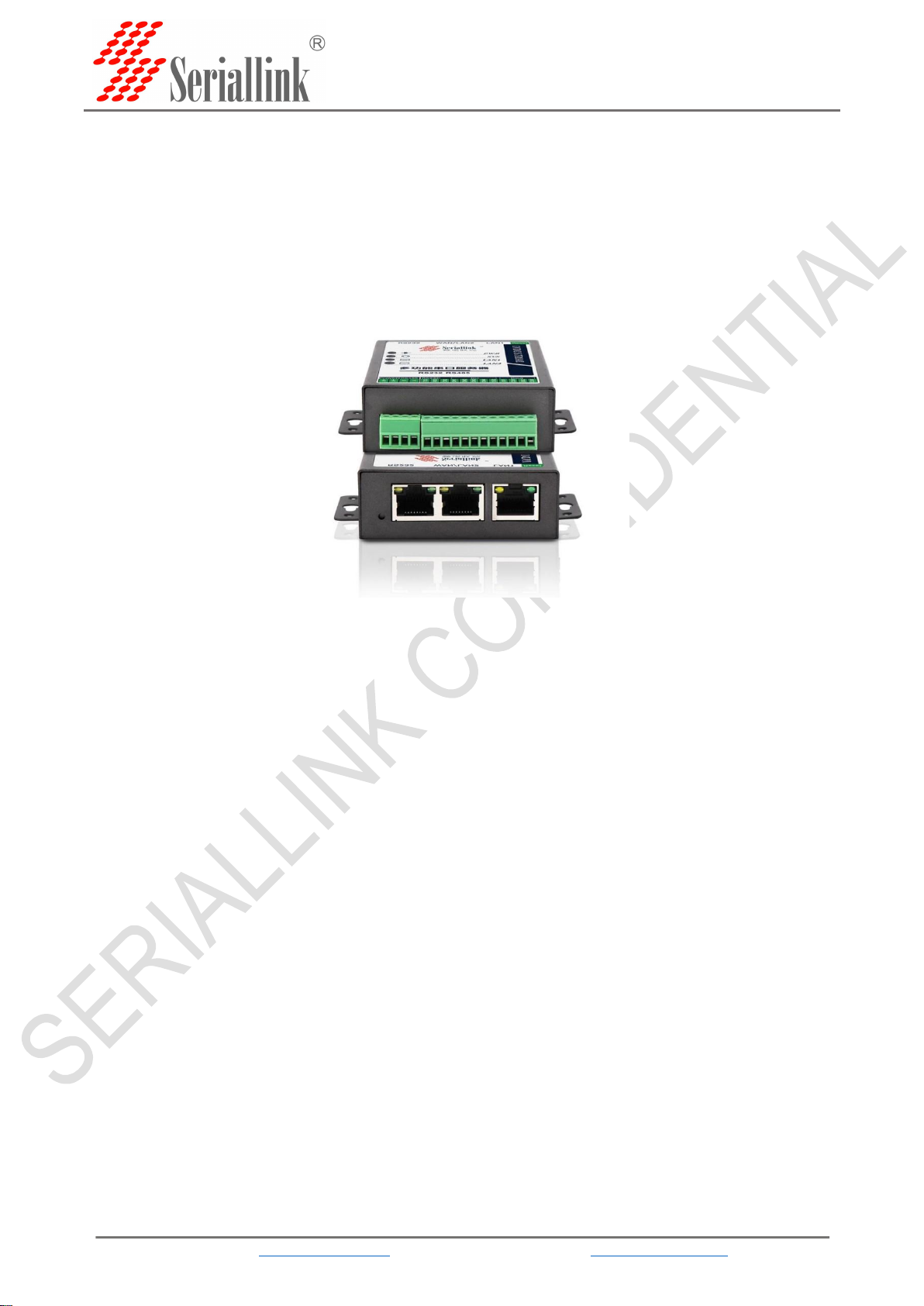
SERIALLINK SLK-S502 serial server converts multi-channel decentralized, low-speed, and different
standard serial devices into Ethernet for centralized management. After installing the virtual serial port, it
can realize remote reading of serial data. SLK-S502 serial server supports multiple working modes,
including TCP server mode, TCP client mode, UDP mode, TCP/UDP Socket, Modbus RTU to Modbus
TCP Server and other working modes, allowing user software to access the serial port through TCP plus
port number Line equipment. In addition, it also supports virtual serial port access to serial devices.
SERIALLINK SLK-S502 supports convenient and quick manual configuration of the IP address through a
browser or Telnet terminal. At the same time, users can also use the easy-to-use Windows management
software to automatically search for serial server devices in the LAN, and perform applications such as
remote configuration management and working status monitoring.
特点:
2 x Adaptive 10/100/1000M Ethernet
1 x R232 serial port (interface is RJ45)
1 x RS485 serial port (interface as terminal)
4 x Digital DI input
1 x Digital quantity DO output, relay output
RS485 serial port with TVS, ESD protection
RS232 serial port with ESD protection
Multiple working modes: TCP server, UDP working mode, TCP client mode, Modbus RTU to Modbus
TCP Server mode
Support WEB and Telnet two configuration methods
Wide voltage: DC9-28V power supply
SLK-S502 Serial server instruction manual
WEB:www.seriallink.cn e-Mail:info@seriallink.net
2
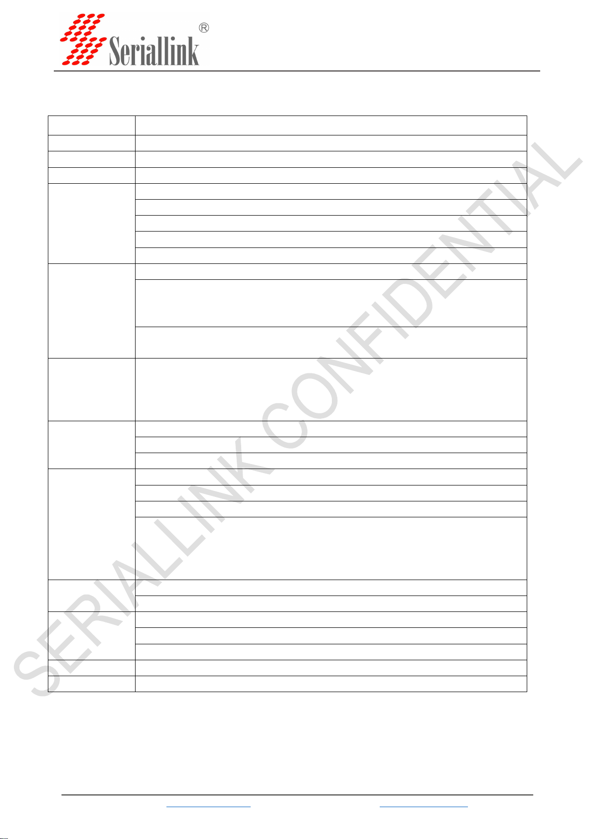
1.2 Detailed parameters
item
description
CPU
Dual-Core 880MHZ
RAM
1Gb DDR3 RAM default, can be customized to support 4Gb DDR3 RAM maximum
NAND Flash
128Mbytes default
Ethernet
interface
Number of interfaces:2
speed:10/100 /1000Mbps, auto MDI/MDIX
Connector:8-pin RJ45
protect:2.4 kV built-in
defaultIP:192.168.0.233
Serial port
Number of serial ports:2,1 x RS232,1 x RS485
The first channel is the RS232 serial port (RJ45) definition
Note: RXD, TXD, GND are connected with the previous terminal definitions to facilitate
terminal wiring)
The second serial port RS485-definition
RS-485-2w: A,B
Serial parameter
Data bit: 5, 6, 7, 8
Stop bits: 1, 1.5, 2
Check Digit: None, Even, Odd
Baud rate: 300bps to 115200 kbps
Serial port
protection
RS232/485 with 15 kV ESD protection
RS232/485 with TVS protection
RS-485Terminal resistance: 120 Ω
Software
performance
Network protocol: TCP, UDP, DHCP ,DNS
Configuration method: Web configuration
Working mode: TCP Server, TCP client, UDP, Modbus RTU to Modbus TCP Server
Windows 95/98/ME/NT/2000, Windows
XP/2003/Vista/2008/7/8/8.1/10 (x86/x64), Windows 2008 R2/2012/2012
R2 (x64)
Use the IP address and port number to access the serial port under LINUX
Physical
parameter
Material: iron
Dimensions with mounting accessories86mm x 70mm x 25mm
temperature
Operating temperature: -40 to 75°C (-40 to 167°F)
storage temperature: -40 to 85°C (-40 to 167°F)
Relative humidity:5 to 95%
power supply
Input voltage: DC9-28V
Warranties
2 year

SLK-S502 Serial server instruction manual
WEB:www.seriallink.cn e-Mail:info@seriallink.net
4
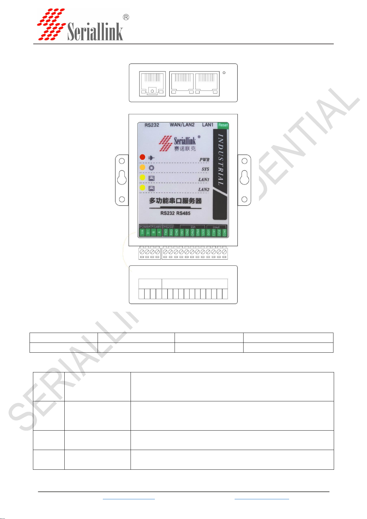
1.3.2 Appearance instructions
Figure 1
RS232
WAN/LAN2
LAN1
Reset
Serial port
Network port
Network port
Restore factory settings button
Figure 2
PWR
Power indicator light
Always bright:Equipment power supply is normal
Not bright:The device is not powered, please check whether the voltage
is 9-28V
SYS
System indicator light
Flashing:Is now Entering the system
Always bright(Very bright):The equipment is running
Always bright(Slightly bright):The system does not start
LAN1
LAN 1 network port
indicator
Flashing/Always bright:Access network
Not bright:Not connected to the network
LAN2
WAN/LAN2 network
port indicator
Flashing/Always bright:Access network
Not bright:Not connected to the network
Figure 1
Figure 2
Figure 3
SLK-S502 Serial server instruction manual
WEB:www.seriallink.cn e-Mail:info@seriallink.net
5
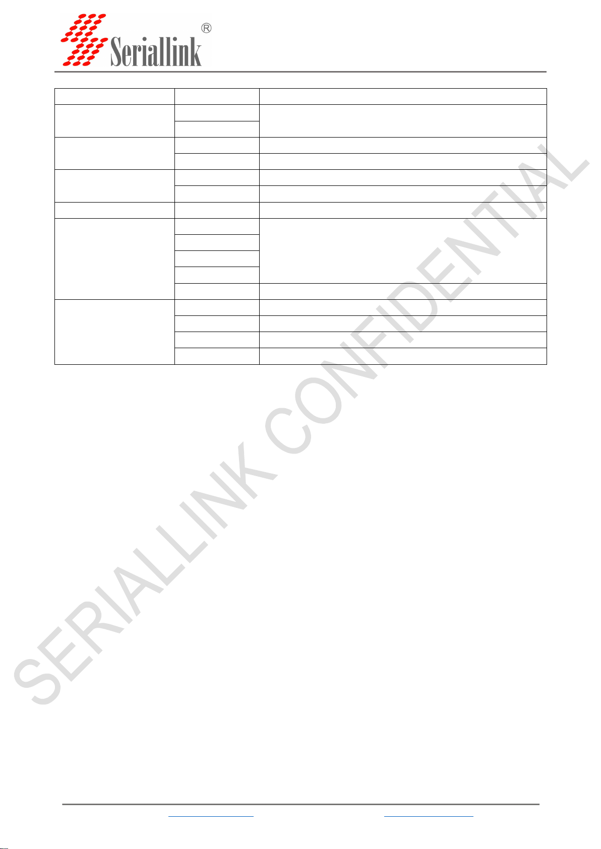
Figure 3
category
parameter
Description
POWER
V+
Power input 9-28V
V-
RS458
B
RS458 Negative end
A
RS458 Positive end
RS232
TXD
RS232 Signal sending end
RXD
RS232 Signal receiving end
GND
Ground terminal end
Din
DIN1
Switching value input end
DIN2
DIN3
DIN4
12VDD
High level output of switching value
Dout
DO1
Switching value output end
COM1
Switching value output public end
DO2
Switching value output end
COM2
Switching value output public end
SLK-S502 Serial server instruction manual
WEB:www.seriallink.cn e-Mail:info@seriallink.net
6
Chapter 2 Parameters configuration
2.1 Preparation before serial port server configuration
Connect one of the LAN ports of the serial server directly to a computer or to a switch. Before logging
in to the Web setting page of the serial server, you need to make sure that the management computer has
an Ethernet card installed.
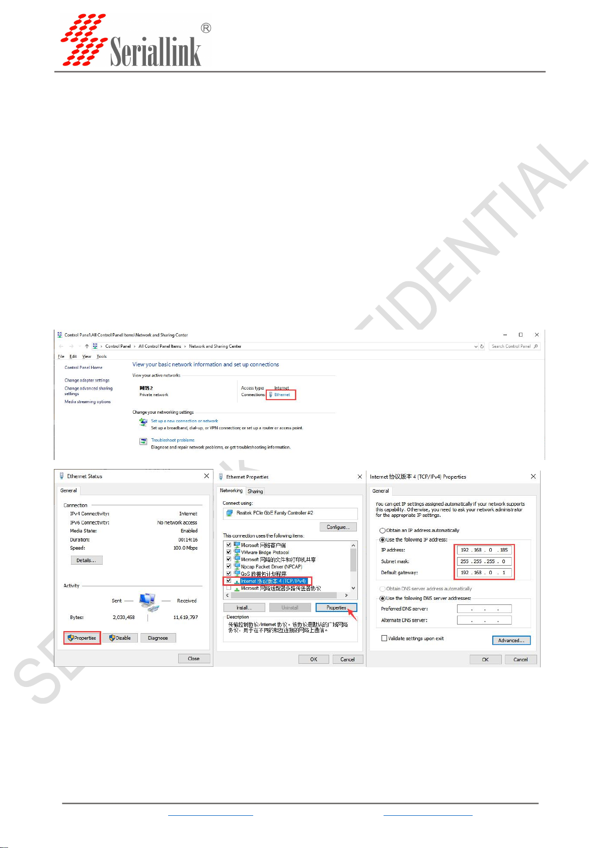
2.1.1 Set a static IP address.
Please set the IP address of the management PC (for example, set it to: 192.168.0.185) and the IP
address of the device's LAN port in the same network segment (the initial IP address of the device's LAN
port is: 192.168.0.233, and the subnet mask is 255.255. 255.0).
Start>>>Settings>>>Control Panel>>>Network&Internet>>>Ethernet>>>Network and Sharing
Center,Modify as follows:
SLK-S502 Serial server instruction manual
WEB:www.seriallink.cn e-Mail:info@seriallink.net
7
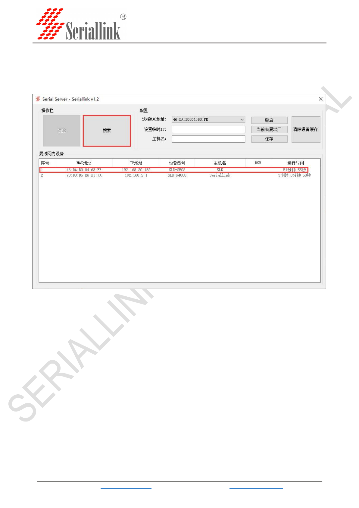
2.1.2 Get IP
The network protocol of the LAN setting is DHCP (dynamic allocation) or you forget the IP address of the LAN
port currently set, you can use the tool Seriallinkv1.2.exe to get the device IP information, as shown in the figure
(LAN has been set to DHCP), search The IP address of the device model SLK-S502 is 192.168.20.182, and then the
network bit in the IP address of the PC is changed to 192.168.20, see 2.1.1 for details.
Double-click the SLK-S502 device information, you can also set temporary IP, change the host name, restart,
restore factory settings and other operations.
Note: After logging in with the modified temporary IP, if the LAN protocol is static, it is recommended to reset
and save in the LAN settings to change it back to the original IP address. For details, see 2.3.1 to change the device
to the original address.
SLK-S502 Serial server instruction manual
WEB:www.seriallink.cn e-Mail:info@seriallink.net
8
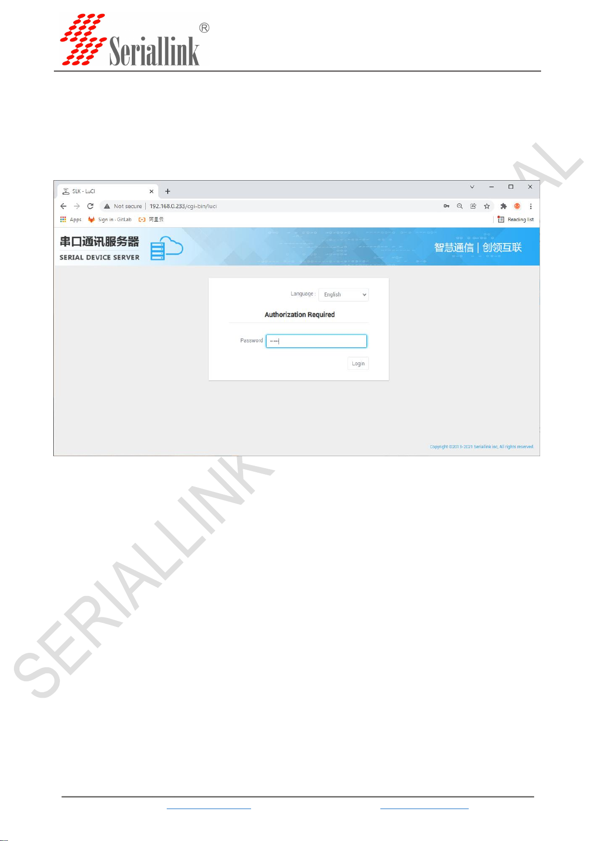
2.2 Login configuration page
Open IE or other browsers, enter the LAN port IP address in the address bar (default is
192.168.0.233), after the connection is established, in the pop-up login interface, log in as the system
administrator (admin), that is, in the login interface Enter the password (the factory default setting of the
password is admin).
The default login password is admin. If the user needs to protect the configuration interface and avoid
being modified by others, you can modify the login password. For detailed operations, please refer to 3.4.
SLK-S502 Serial server instruction manual
WEB:www.seriallink.cn e-Mail:info@seriallink.net
9
2.3 Network Setting
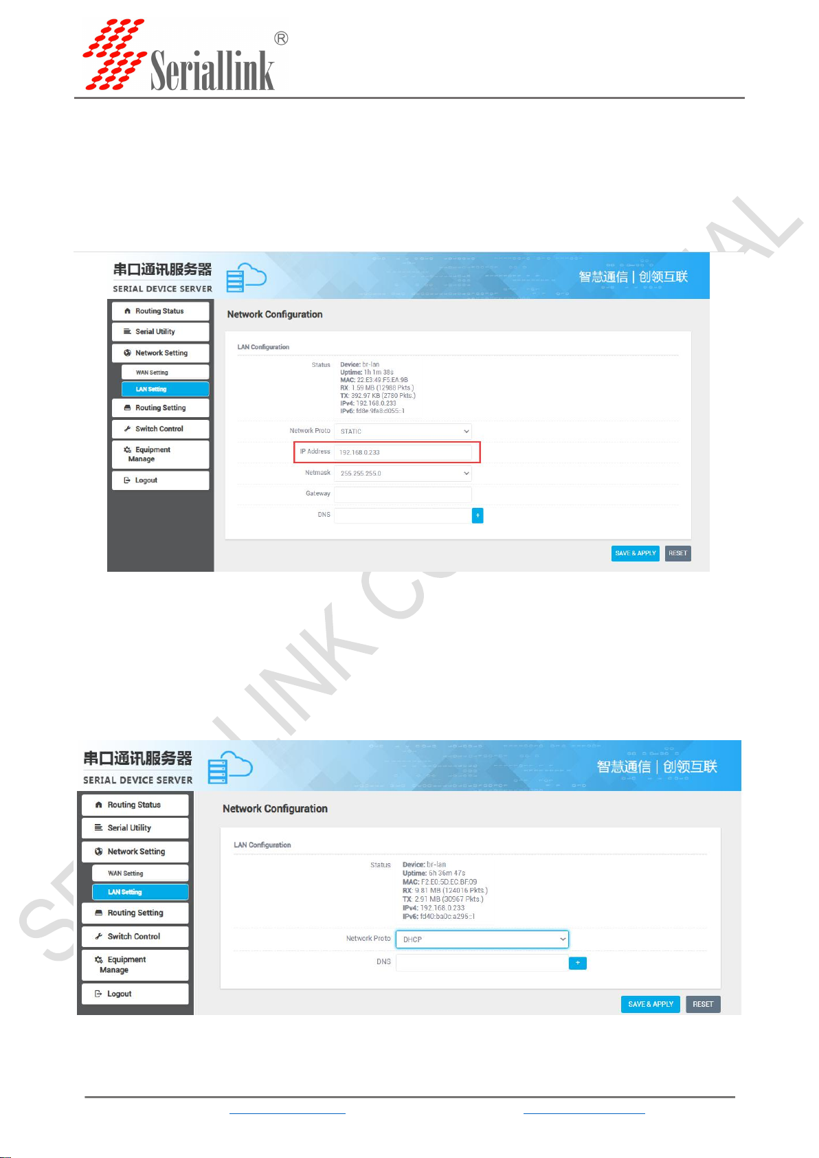
2.3.1 Modify the static login page address
The default static address of the serial server is 192.168.0.233. You can see the network information
in the navigation bar "Network Setting" >>> "LAN Setting". You can also modify the static IP address, and
after the modification, the new IP address will be used to log in to the page.
2.3.2 DHCP
The LAN port of the serial server is connected to a switch or router, and you can select the DHCP
network protocol to automatically obtain an IP address.after the computer is connected to the switch, log
in to the page through the IP automatically obtained by the serial server DHCP. At this time, the IP of the
serial server is assigned by the upper-level router. You need to check which IP the upper-level router
assigns to the serial server, or use Seriallinkv1.2.exe Software, obtain the IP address, see 2.1.2 for
details.
SLK-S502 Serial server instruction manual
WEB:www.seriallink.cn e-Mail:info@seriallink.net
10
2.4 Serial port configuration
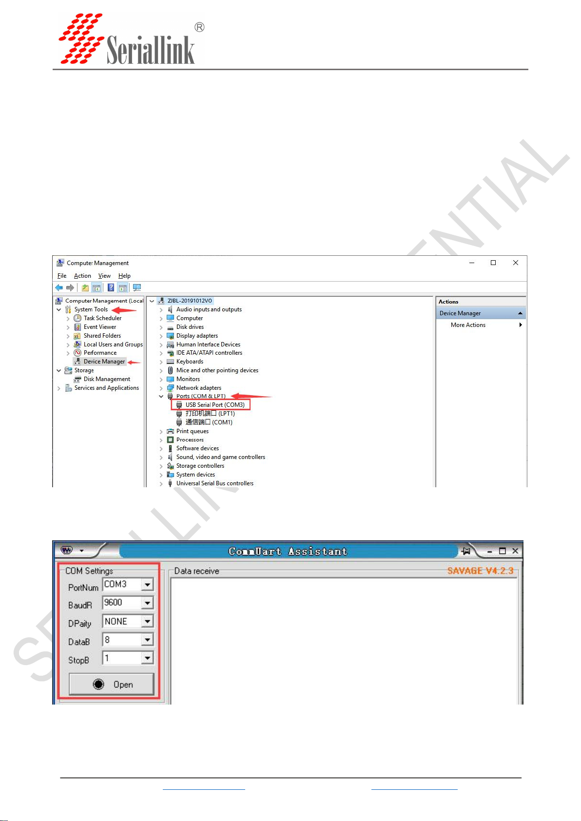
2.4.1 Use tools and preparation
Select Serisl Utility>>>PROT 2 in turn to configure a port according to your needs. Here is an
example of PORT 2. Connect the computer serial port, check the serial port as shown in the figure below,
right click on the desktop This PC>>>Manage>>>System Tools>>>Device Manage>>>Ports(COM &LPT).
Use tools UartAssist.exe and NetAssist.exe for TCP Server, TCP Client, UDP Server, and UDP Client
simulation, and ModSim32.exe and ModScan32.exe for Modbus TCP simulation. You can use your
familiar serial port and network debugging software. The difference between UDP Client and UDP Server
is whether it needs to communicate with only a specific IP address. UDP Client only communicates with a
specific server IP address.
The settings of UartAssist.exe are as follows. The baud rate and stop bit can be changed as required.
After the setting is completed, click Open.
SLK-S502 Serial server instruction manual
WEB:www.seriallink.cn e-Mail:info@seriallink.net
11
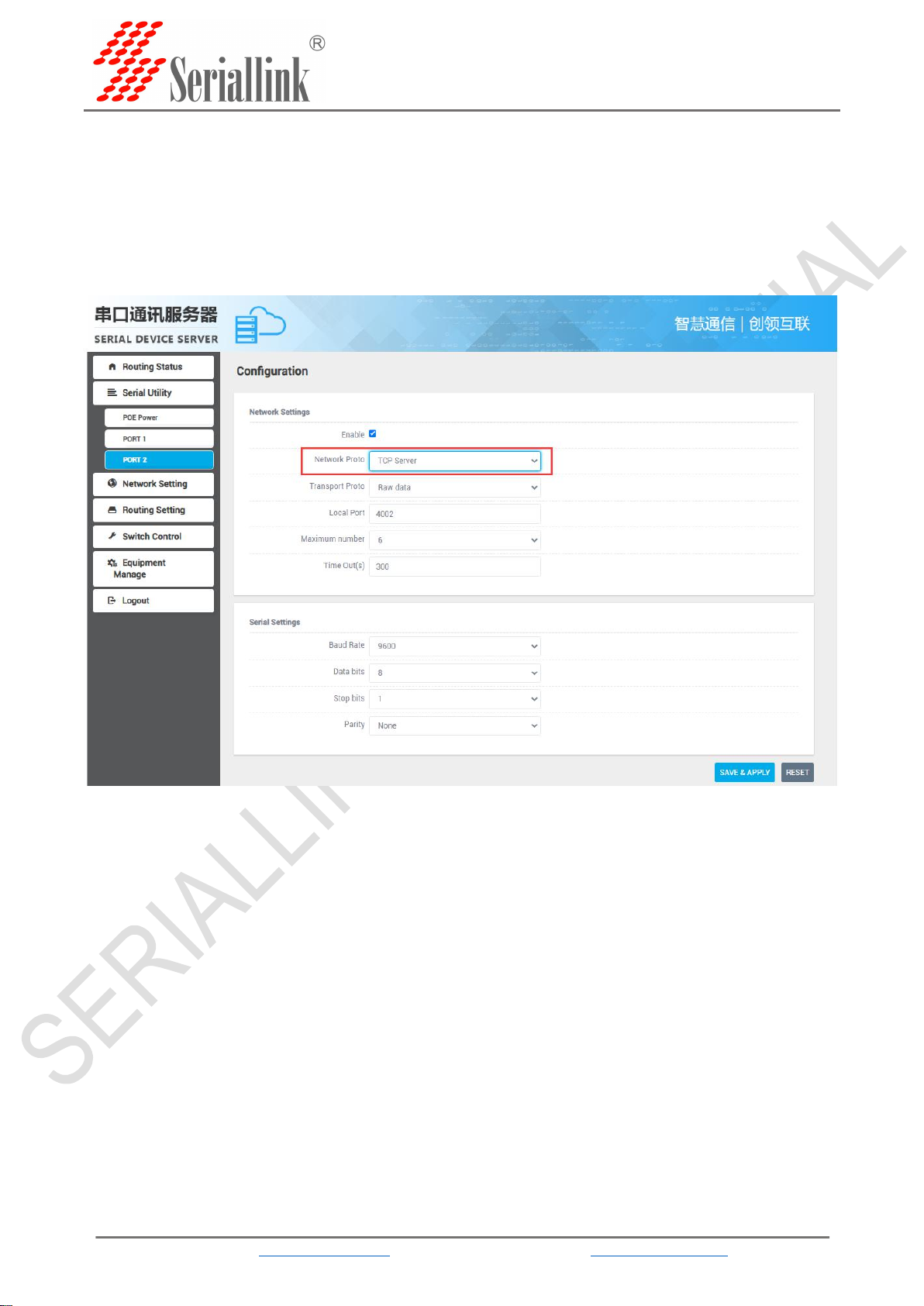
2.4.2 TCP Server
Select Serisl Utility>>>PORT2 in turn,select TCP Server as the network protocol, and choose the
data type according to your needs. Generally, the choice is "Raw date". You need to remember the local
port after setting. When establishing a TCP connection, you need to use the IP address and port number
of the serial server.Configure the baud rate, data bit, stop bit and parity bit of the serial port through the
serial port configuration bar according to your needs. After the configuration is complete, click SAVA &
APPLY.
Maximum number: The default is 6, which means that up to 6 TCP Clients are supported to connect
to the same serial port.
Time Out (s): The default is 300, which means that after the TCP Server establishes a connection, if
there is no data, the connection will be disconnected after 300 seconds. If you need a permanent online
connection, you can set the value to 0.


SLK-S502 Serial server instruction manual
WEB:www.seriallink.cn e-Mail:info@seriallink.net
13
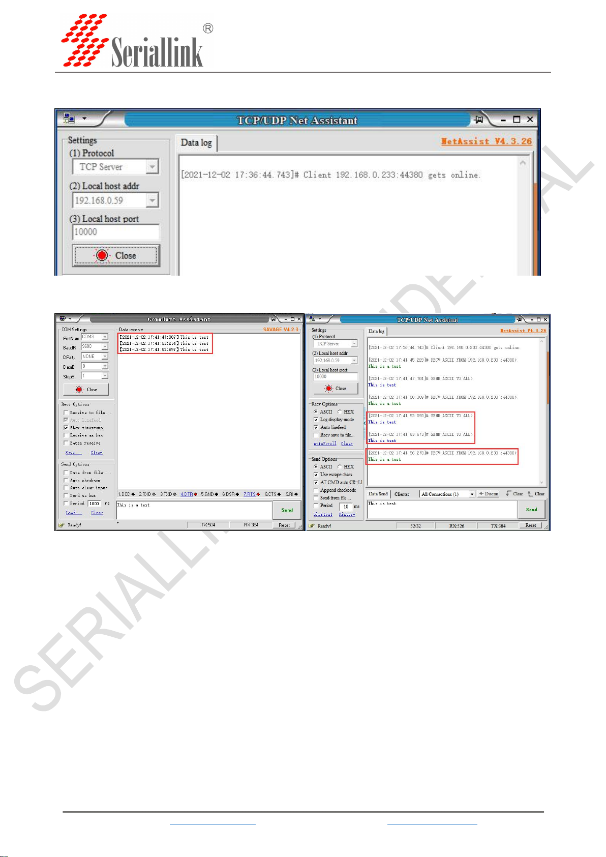
2.4.3 TCP Client
Protocol select TCP Server, Local host addr select the IP address set by the computer, which is in the same
network segment as the device's LAN port IP. The Local host port is the default, and the client settings need to use
Local host addr and Local host port,click Open.
Select Serisl Utility>>>PORT2 in turn,select TCP Client as the network protocol, and the server IP
and port number should be consistent with the software settings. Configure the baud rate, data bit, stop
bit and parity bit of the serial port according to your needs through the serial port configuration bar. After
the configuration is complete, click SAVA & APPLY.
SLK-S502 Serial server instruction manual
WEB:www.seriallink.cn e-Mail:info@seriallink.net
14
After saving and applying, the software will print "[2021-12-02 17:36:44.743]# Client 192.168.0.
233:44380 gets online.", indicating that the connection is successful.
TCP Client and TCP Server send and receive data diagram.

SLK-S502 Serial server instruction manual
WEB:www.seriallink.cn e-Mail:info@seriallink.net
15
2.4.4 UDP Server
Select Serisl Utility>>>PORT2 in turn,select UDP Server as the network protocol, choose the data
type according to your needs. Generally, the choice is Raw date. You need to remember the local port
after setting. When establishing a UDP connection, you need to use the IP address and port number of
the serial server. The baud rate, data bit, stop bit and parity bit of the serial port are configured according
to your needs. After the configuration is complete, click SAVA & APPLY.
Maximum number: The default is 6, which means that up to 6 UDP Clients are supported to connect
to the same serial port.
Time Out (s): The default is 300, which means that after the UDP Server establishes a connection, if
there is no data, the connection will be disconnected after 300 seconds. If you need a permanent online
connection, you can set the value to 0.
SLK-S502 Serial server instruction manual
WEB:www.seriallink.cn e-Mail:info@seriallink.net
16
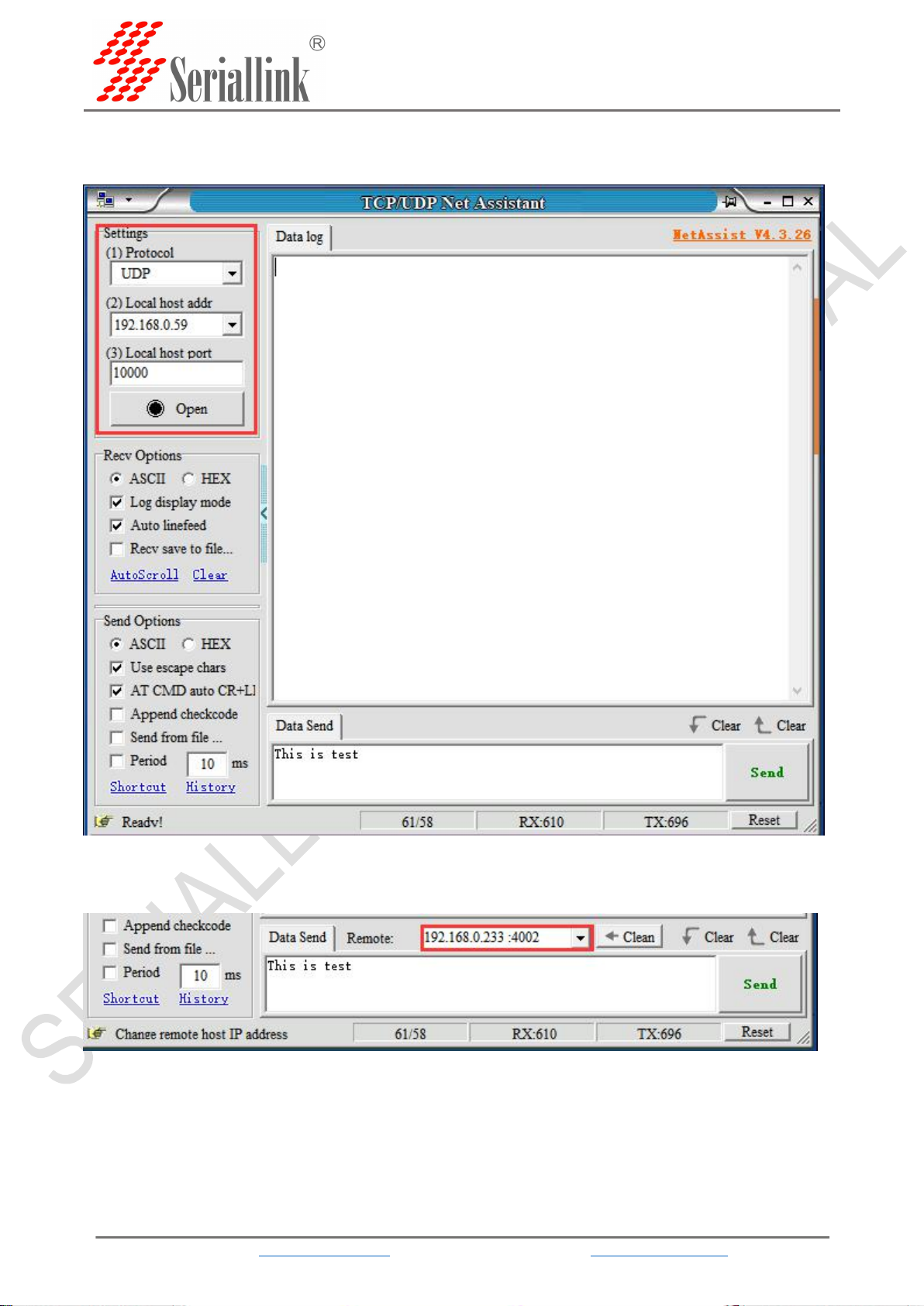
The software settings are as follows, Protocol selects UDP, Local host addr selects the same network
segment IP set by the computer and the device, and the Local host port defaults to it. Click Open after
setting.
After opening, fill in "192.168.0.233:4002", the server's IP address and port number, separated by
‘:’.

SLK-S502 Serial server instruction manual
WEB:www.seriallink.cn e-Mail:info@seriallink.net
18
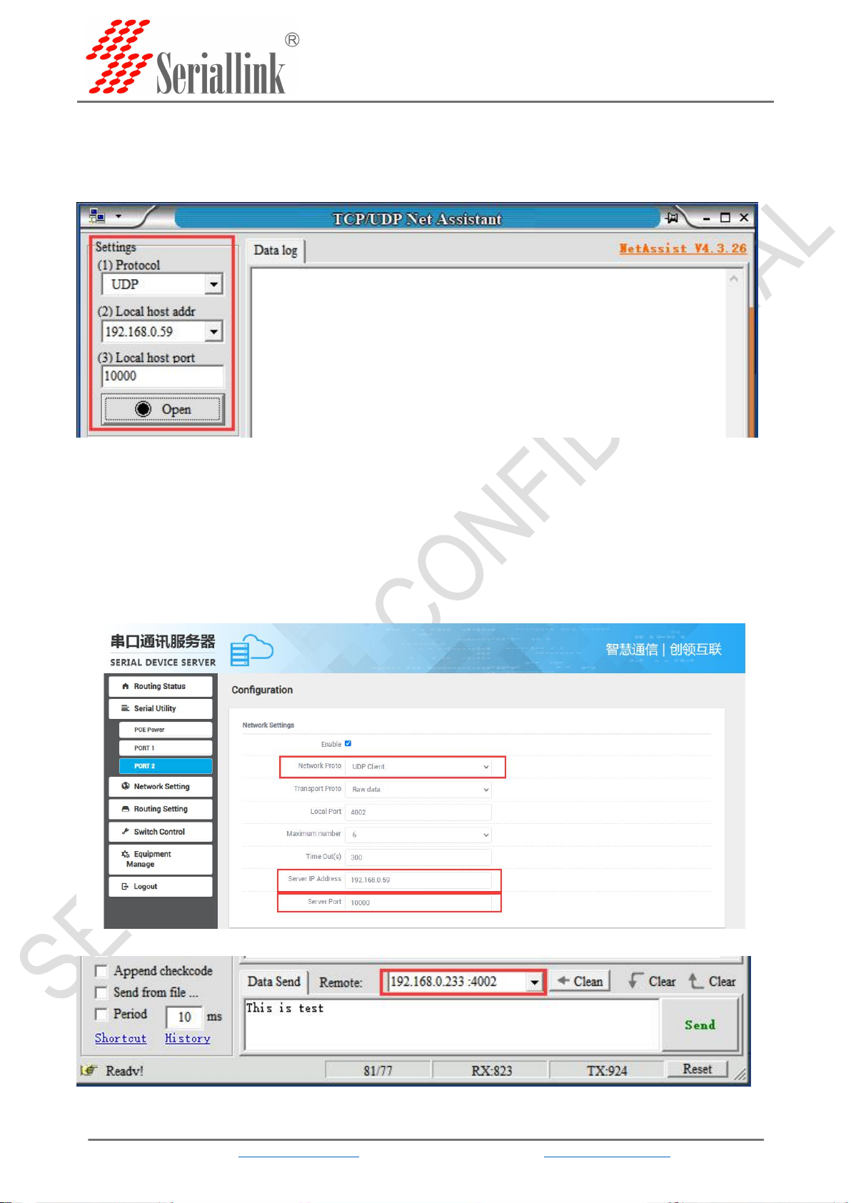
2.4.5 UDP Client
Protocol select UDP, Local host addr select the IP address set by the computer, which is in the same
network segment as the device's LAN port IP. The Local host port is the default, and the client settings
need to use Local host addr and Local host port,click Open.
Select Serisl Utility>>>PORT2 in turn,choose UDP Client as the network protocol, and choose the
data type according to your needs. Generally, the choice is Raw date. You need to remember the local
port after setting. The IP address and port number of the serial port server are used when establishing a
UDP connection. Compared with UDP Server, UDP Client has an additional server IP address and server
port number. The purpose of this addition is to ensure the security of UDP data transmission. Network
data only receives data from the server IP and server port number. The rest of the data are denied access.
Configure the baud rate, data bit, stop bit and parity bit of the serial port through the serial port
configuration bar according to your needs. After the configuration is complete, click SAVA & APPLY.
In the next step, the following information needs to be filled in the software.
Table of contents


