Sermatec LV3584 User manual

1/16
LFP Storage System
LV3584 User Manual
Document No.:
Version:V1.0

2/16
Contents
LV3584 USER MANUAL ...............................................................................................................................1
1. SCOPE AND SIGN ....................................................................................................................................3
2. PRODUCT COMPONENTS ...................................................................................................................... 7
2.1 PRODUCT MAIN COMPONENTS ..........................................................................................................7
2.2 BATTERY SYSTEM PORT ..................................................................................................................... 7
2.3 SYSTEM DIAGRAM ................................................................................................................................8
2.4 ANNOUNCEMENTS OF PARALLEL CONNECTION BEFORE START-UP .......................................10
2.5 BATTERY SYSTEM PORT ................................................................................................................... 11
2.6 PACKAGE ............................................................................................................................................. 12
3. PRODUCT ELECTRICAL CHARACTER ............................................................................................... 13
3.1 MODULE SPECIFICATION .................................................................................................................. 13
4. BATTERY MANAGEMENT SYSTEM (BMS) FUNCTION ......................................................................14
5. PRODUCT EXTERIOR REQUIREMENT ............................................................................................... 14
6. DATA STORAGE REQUIREMENT .........................................................................................................14
7. PACKING, TRANSPORTATION, STORAGE REQUIREMENTS ...........................................................14
7.1 PRODUCT PACKAGE PACKING REQUIREMENTS .......................................................................... 14
7.2 PRODUCT TRANSPORTATION REQUIREMENTS ............................................................................ 14
7.3 PRODUCT STORAGE REQUIREMENT .............................................................................................. 14
8. REGULAR MAINTENANCE............................................................................................................................... 15
8.1 SOC CHECK....................................................................................................................................................... 15
8.2 CABLE CHECK.................................................................................................................................................. 15
8.3 BALANCE............................................................................................................................................................15
8.4 OUTPUT RELAY CHECK................................................................................................................................. 15
8.5 HISTORY CHECK.............................................................................................................................................. 15
8.6 MAINTENANCE..................................................................................................................................................15
3/16
1. Scope and Sign
This User Manual is to describe the technical indexes of LV3584 Battery Module produced by
Shanghai Sermatec Energy & Technology Co.,Ltd.And would be used as the basis of product
inspection by Sermatec Quality Department and Client.
This manual includes important description given below: The installation and usage of LV3584
storage product must follow this manual. The design of the product and the tests are based on the
global safety requirements. But same for all the electricals, you must follow some prevention
strategies during installation and operation. To decrease the risk of human injury and make sure that
the product is installed and operated safely, you must read and follow all the descriptions,
announcements and warnings carefully.
Signs
Danger
Fatal Voltage!
Battery module would generate DC voltage, and would cause fatal
voltage and electric shock.
Only trained person can do the installation of the battery module.
Warning
Damaged battery system may lead to risk of human injury.
Don’t draw the connector when the system is working!
Cut off on several power source, and make sure that there is no
voltage left.
Alarm
Decrease the possibility of battery module system error or risk on
life-cycle.
Read
Sings
Please firstly read the User Manual and Datasheet before starting
using the battery!
4/16
Sign
Danger! Careful!
Sign l
Be Careful of Electric Shock!
Sign
Don’t put the system beside inflammables.
Sign
Don’t connect +/- reversely.
Sign
Don’t put the system beside fire.
Sign
Isolate the system from children and pets.
Sign
Recycle Sign
5/16
Sign
Waste Electrical and Elecctronic Equipment (WEEE) Command
(2012/19/EU)
Sign
EMC Certificate Sign
Sign
TÜV SÜD Safety Certificate Sign
Danger: Battery provides electricity. When battery is short-circuit or wrongly installed,
may lead to danger of burn or fire.
Danger: Fatal voltage exists in battery port and cables. Touch cables or ports could lead
to serious human injury or death.
Warning: Please don’t open or change the appearance of the battery module;
Warning: When operate on the batteries, please wear proper Personal Protective
Equipment (PPE), e.g. rubber gloves, rubber boots, goggles.
Warning: LV3584 system working temperature range: 0℃~50℃; Proper temperature: 18℃~ 28℃. If it
exceeds the range, the battery life-cycle might be decreased or even cause battery system over/low
temperature warning or protection. And may influence warranty.
Warning: On the battery installation, installers shall follow the local installation standards.
Attention: Improper setting or service may permanently destroy the battery.
Attention: Wrong inverter parameters may lead to battery early aging.
Alarm
1)During installation or operation, please carefully read the user manual (in the
attachment), this is very important and necessary. If you don’t follow the instruction or
warnings in this document, it could lead to electric shock, serious damage, or death, or destroy the

6/16
battery and impossible to control the battery.
2)During Long period of storage, it is necessary to charge every half a year, SOC should be higher
than 90%;
3)Battery need to be charged before 12 hours after fully charged.
4)Cables need to be sufficiently insulated.
5)During maintenance, all the battery ports must be disconnected.
6)If you find any error, please directly contact manufacturer in 24 hours.
7Please don’t use cleanse to wash the battery.
8)Please don’t expose the battery to inflammables or pungent chemicals or steam;
9)Please don’t paint any part of the battery, including inside or outside components.
10)Please don’t directly connect battery and PV panels.
11)Except authorized Sermatec staffs, don’t open, repair or disassembly batteries. Our company
doesn’t take responsibility for any results due to disobeying safety operation or design, production
and device safety standards.
12)Direct or indirect damage due to above items, is not included in Sermatec warranty.
13)It is not allowed to insert foreign matter to any part of the battery.
1.2Before connection
1)Please firstly check the product and pack list after opening the case. If there is any
damage or missing, please contact local dealer.
2)Before installation, please make sure that grid power is cut off, and make sure that the battery is at
‘Off’ condition.
3)Connection must be correct, don’t connect battery +/- reversely, and make sure that the battery is
not short-circuited.
4)Don’t connect battery directly with AC power.
5)Battery inner BMS is 51.2VDC, please don’t connect the battery in series.
6)The battery system shall be grounded sufficiently, and the resistance shall be smaller than 100mΩ.
7)Make sure that the battery system electrical parameters is compatible to related devices.
8)Make the battery far from water and fire.
1.3Usage
1)If you need to move or repair battery system, you must cut off the power, and totally shut
down the battery.
2)Don’t connect the battery with different types of batteries
3)Don’t connect the battery with malfunctioning or incompatible inverters.
4)Don’t disassembly the battery (When the QC label is teared or destroyed).
5)When fire occurs, please use dry powder extinguisher, don’t use liquid extinguisher.

7/16
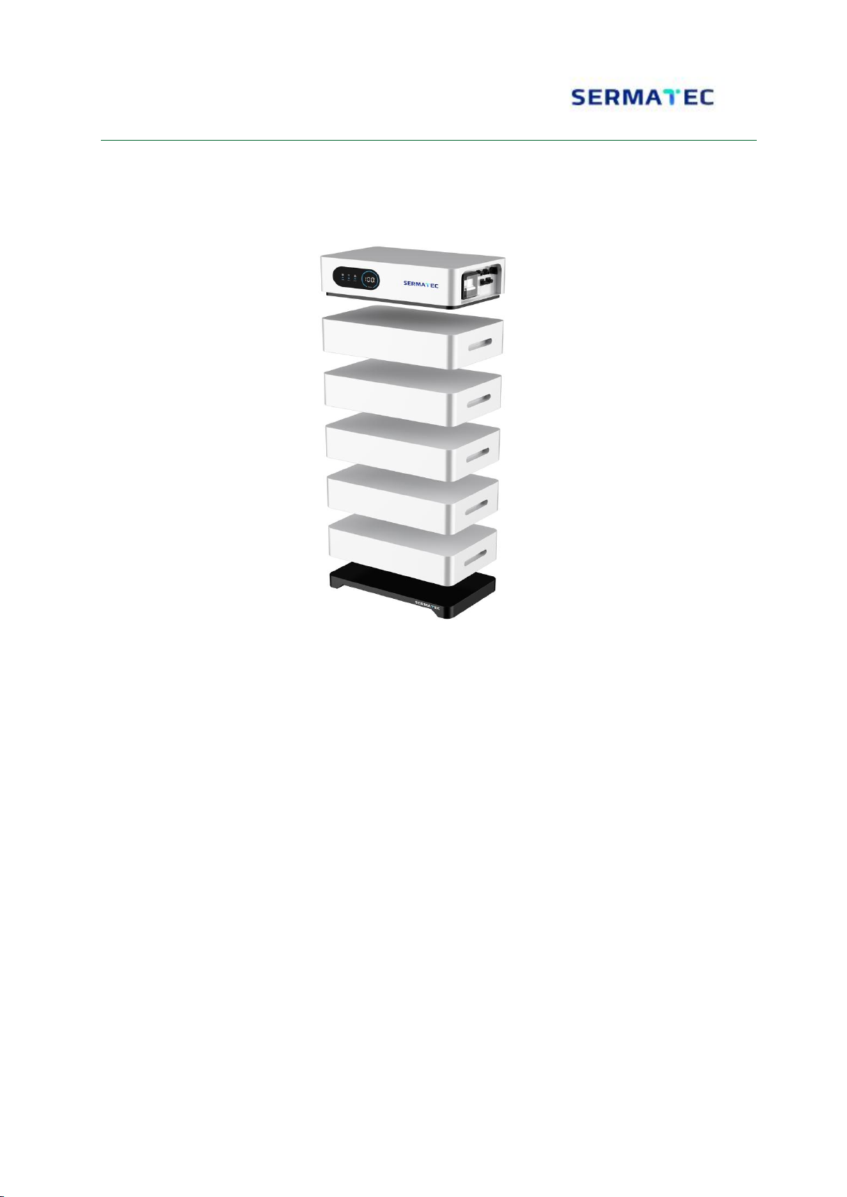
2. Product Components
2.1Product main components
Component
Specification
Figure
Battery Box
70Ah 1P16S
Low Voltage BMS
Maximum Current 125A
Pedestal
Width 352mm Depth 570mm Height 60mm
Power Cables
Orange and Black 1xAWG3,Surlok
Connector
Communication
Cable
CAN, RS485 communication cable
Battery Output
Surlok Port
2.2 Battery System Port
Power Output
Communication
Power Switch
SOC Display,
Status Indicator,
WiFi indicator,
Alarm Indicator

8/16
2.3 System Diagram
Model Type
LV3584
Battery Cell
LFP
Battery Energy(kWh)
7.16
10.75
14.33
17.92
21.5
25.08
28.67
Battery Voltage(Vdc)
51.2
Battery Capacity(AH)
140
210
280
350
420
490
560
Module Number(pcs)
2
3
4
5
6
7
8
Module Energy(kWh)
3.584
Module Voltage(Vdc)
51.2
Module Capacity(AH)
70
Cell Number(pcs)
16
Charging Voltage(Vdc)
57
Nominal Charging
Current(A)
28
42
56
70
84
98
112
Suggested Charging
Current(A)
70
105
125
Charging Current(A,
Max.@15S)
130

9/16
Cut-off Discharging
Voltage(Vdc)
47.4
Nominal Discharging
Current(A)
28
42
56
70
84
98
112
Suggested Discharging
Current(A)
70
105
125
Maximum Discharging
Current(A)
125
Efficiency(%, ≤0.5C-rate)
96
Depth of Discharge%)
90
Dimension(W*D*H,mm)
570*352*
537
570*352*
693
570*352*
849
570*352*
1005
570*352*
1161
570*352*
1317
570*352*
1473
Communication
RS485\CAN
Protection Level
IP55
Weight (kg)
Life Cycle(Years)
15+
Working Temperature(℃)
0~50
Storage Temperature(℃)
-20~60
Altitude(M)
<2,000
Product Certificate
IEC62619 CE
Transport Certificate
UN38.3
1)Controller Dimension
(W*D*H, mm)
2)Module Dimension
(W*D*H, mm)
3)Pedestal Dimension
(W*D*H, mm)
570*352*165
570*352*156
570*352*60
10 /16
2.4 Announcements of parallel connection before start-up
1. Install and pile the batteries correctly, and then turn the switch to ‘ON’ position, start up the
batteries. When the batteries are installed wrongly, it would lead to startup error. After starting up
the system normally, the batteries would distribute the address automatically. The main control
box at the top would judge through the data sent from the below batteries.If the data sent from the
batteries are judged to be normal, the batteries would be started up successfully, otherwise
startup would fail.
2. Shut down. When the battery is not charged or discharged, then you can shut down the battery.
The switch can be used to cut-off the circuit when the battery is powering the loads. But to protect
outer devices, we suggest to firstly shutdown the loads and stop charging/discharging and then
turn the switch to ‘Off’, and make sure that the indicators are OFF, so that the battery is shut
down.

11 /16
2.5 Definition of communication pin sockets
CAN: Communication Terminal:(RJ45 port) Follow CAN Protocol, used for
communication between battery and inverter.
RS485: Communication Terminal:(RJ45 port) Follow RS485 Protocol ,used for
communication between battery and inverter.
CAN
RS485
Baud
Rate
500K Default
19200 Default
No.
Description
1
CANH
RS485A
2
CANL
RS485B
3
GND
GND
4
5
6
--
7
--
8
--
12 /16
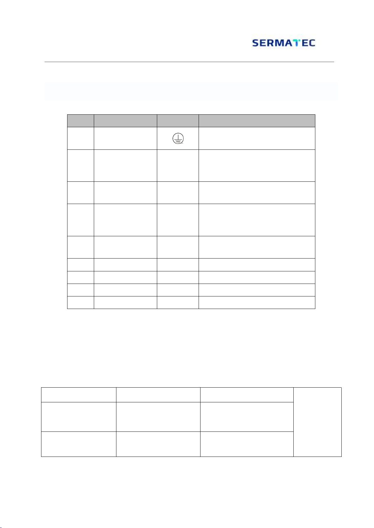
LV3584 LFP Battery Interface Description
No.
Name
Label
Function Description
1
Grounding Port
Used for Battery Grounding
2
Switch
Power Switch, while at ‘ON’ status, system
started up; While at ‘Off’ status, the system
cannot be started up, cannot output power.
3
RUN Indicator
RUN
When switch is at ‘ON’, the RUN indicator
would be ‘ON’.
4
SOC indicator
POWER
When the switch is at ‘ON’ status, the
control box would display SOC based on
the battery data.
5
WIFI and FAULT
WIFI/FAULT
Status indicator, Fault Indicator, WiFi
indicator
6
CAN Port
CAN
Used for communication
7
RS485 Port
RS485
Used for communication
8
- Input/Output Port
“-“
Battery Input/Output - Port
9
+ Input/Output Port
“+“
Battery Input/Output + Port
2.6 Package
LV3584 Box,Inner Dimension:650mm*430mm*260mm;Outer Dimension:670mm*445mm*280mm
LV3584 Accessory Box,Outer Dimension:600mm*100mm*40mm
Battery Dimension:570mm*352mm*156m
Accessory List
Accessory Name
Specification
Figure
Grounding Cable
Yellow-Green/1
Meter/10AWG/Two side
TL6-6 Circle Connector
nut, screw, bolt
Full Set
Outer Accessory List
13 /16
Accessory Name
Specification
Figure
+ Outer Power Cable
Orange/3m/4AWG/SURLOK
Connector/25-8 Connector
- Outer Power Cable
Black/3m/4AWG/SURLOK
Connector/25-8 Connector
Outer CAN
Communication Cable
Black/3.0m/STP/Two-Side RJ45
Connector
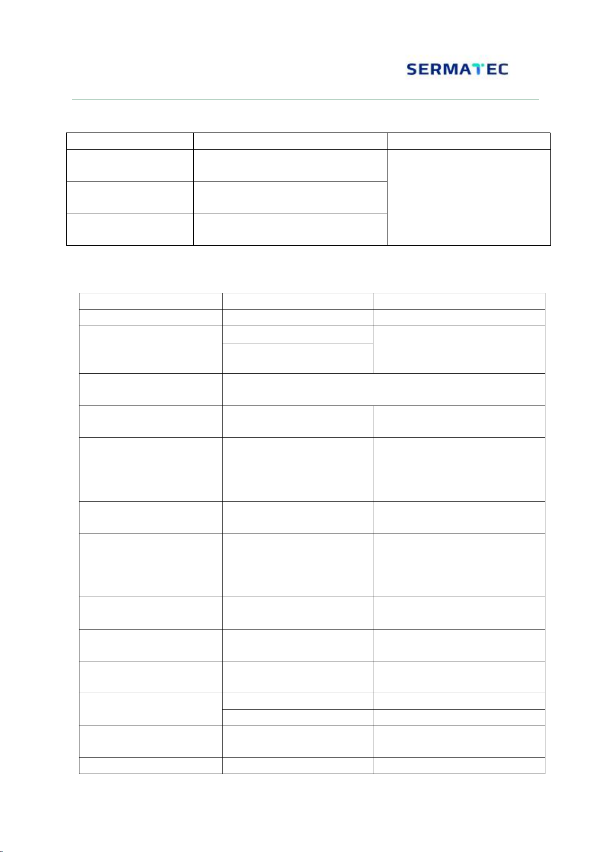
3. Product Electrical Character
3.1 Module Specification
Parameter
Specification
Remark
3.1.1Nominal Voltage
51.2V
3.1.2Nominal Capacity
Typical:70Ah
Charge normally and lay 0.5-1h,
0.1C discharge to 47.2V or
discharge until BMS protect.
Minimum:69Ah
3.1.3Nominal Charge
Method
0.2C Constant Current Constant Voltage (57V) charge until
discharge current 0.01C
3.1.4Nominal Discharge
Current
35A
3.1.5Discharging Protect
Current
125A
15s delay protection. 1 minute
after protection resume or directly
resume when there is charge
current
3.1.6Nominal Charging
Current
35A
3.1.7 Charging Protect
Current
125A
15s delay protection. 1 minute
after protection resume or directly
resume when there is discharge
current
3.1.8Battery Inner
Resistance (BMS Excluded)
Inner Resistance<20mΩ
3.1.9Upper Value of
Charging Voltage
57.6±0.1V
Suggested Charging Voltage
57±0.5V
3.1.10Lower Value of
Discharging Voltage
47.2±0.1V
3.1.11Working Temperature
Charging
-10~60℃
Discharging
-10~60℃
3.1.12 Working Humidity
5%~95%
No condensation, system can work
normally
3.1.13Storage Temperature
-25℃~65℃

14 /16
4. Management System (BMS) Function
BMS has following function: Over-charging protection, over-discharging protection, high-voltage
protection, low-voltage protection, charging over-current protection, over-temperature protection,
low-temperature protection, short-circuit protection, battery cell balance function.
5. Product exterior Requirement
Battery exterior keeps clean, and installer need to firstly clean dusts and scrap iron before
installation and power on. And installer shall keep the area clean.
6. Data Storage Requirement
The battery test data must be stored in the database. So that the data can be checked with SN
number.
7. Packing, Transportation, Storage Requirements
7.1 Product Package Packing Requirements
Battery module precharge to 60%~70% SOC or deliver according to customer requirement. The
battery remaining SOC after going on boat depends on the storage time and storage condition.
1. Battery Module meets UN38.3 Certificate Standard.
2. Especially, the package must follow Revised Special Rule of Road Cargo Transportation and
Existing Dangerous Goods Act.
7.2 Product Transportation Requirements
Battery must be prevented from strong shaking, impact, extrusion, and must be prevented from
sunlight and rain. The battery can be transported through car, train, boat, air etc. for transportation.
The battery shall be lightly moved during assembly and disassembly, and cannot be dropped, rolled
and pressed hardly.
7.3 Product Storage Requirement
Battery shall avoid exposure to corrosive matters, and shall be away from fire and heat source.
Suggestion for storage:
a)Long-time Storage (more than 3 months), battery shall be stored under 5~45℃, relative
humidity 65%, without corrosive air. Battery module shall be stored under 5~45℃, dry, clean,
with good ventilation. Battery shall be charge to 50~55% SOC. And it is suggested to do a
chemical active charging and discharging every 3 months. The maximum time interval cannot be
longer than 6 months.
Note: If the battery is not long-time stored in the correct way mentioned above, the battery life
cycle would be decreased greatly.

15 /16
8. Regular Maintenance
Check the Battery Voltage through Monitoring. Check whether the system voltage is normal or
not. For example: Cell voltage is abnormally high/low.
8.1 SOC Check:
Use Monitoring system to check Battery System SOC status, and check the battery SOC is
normal or not.
8.2 Cable Check:
Check all the cables with eyes. Check whether there is breakage, aging, loosing.
8.3 Balance:
Long-time of not fully charged would lead to battery module unbalance. Solution: Do balance
maintenance every three months (Charge to 100% SOC). Generally speaking, this process can
be achieved automatically through communication between system and outer devices.
8.4 Output Relay Check:
When load is small (low current), control the switch of output relay, to hear the sound from the
relay, so that you will know that the relay is working normally.
8.5 History Check:
Analyze history records, check whether there is accident (warning, protection), and analyze on
the reasons.
8.6 Maintenance:
For the functions that needs maintenance during restarting, it is suggested to do maintenance
every 6 months.
Destroyed batteries could have electrolyte leakage or generate combustible gas. If there is fire,
please call local Fire Alarm Number. If the destroyed batteries need recycle, the recycling
process shall follow the local rules to achieve the recycle of related items.

Table of contents
Other Sermatec Storage manuals


Popular Storage manuals by other brands


Sun Microsystems
Sun Microsystems StorEdge N8400 Installation, configuration, and service guide

Wolfcraft
Wolfcraft 5125000 Translation of the original operating instructions

Maxtor
Maxtor DiamondMax 21 Specifications

Fujitsu
Fujitsu MPG3XXXAH product manual

OnStream
OnStream SC30 installation guide

Winbond
Winbond W632GG6KB Series manual


