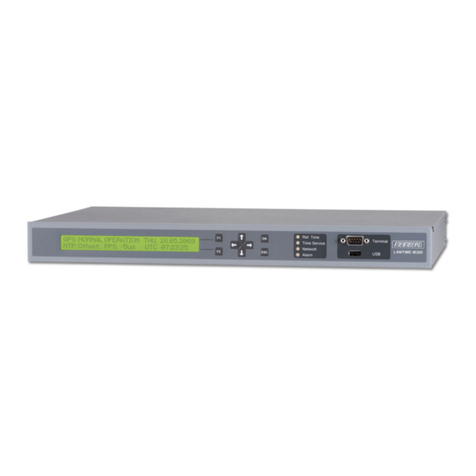
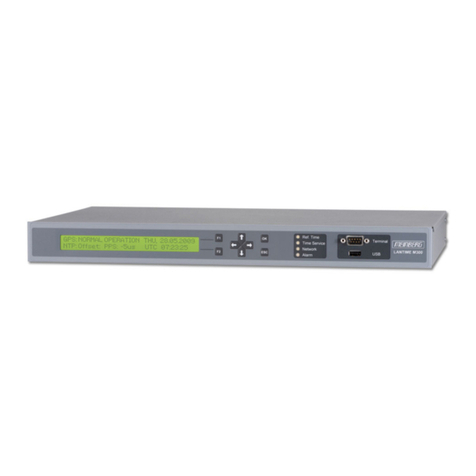
SERTEL T-GPS-300 User manual


SERTEL ELECTRONICS (PVT)LTD COMPANY PROFILE
Dear Customer,
GPS Based time synchronization for various equipments of electrical / Instrumentation
and computers.
Ref: - Power generation / Distribution
With reference to the above we are glad to inform you and also introduce ourselves that we are the
manufacturers of time synchronization with an accuracy of 1 micro sec for time stamping. This time
stamping will facilitate to identify the problem First caused / trip to another where by all contactors /
Relays connected to cascading operation.
The salient features of the Synchronisation system which is as following:
Master Clock and Slave Clock
•Synchronised to GPS receiver (through satellite)
•The slave clock can be connected to entire factory at various locations displaying the same
•time through out the factory in terms of hour min & Sec.
Time Synchronisation
a) Electrical equipments Synchronisation
Time synchronization synchronizing the electrical parameters such as event recorder, disturbance
recorder, fault recorder and sequential event recorder. PLC’s, data acquisition system and other
intelligence or RTU (remote terminal unit).
b) Instrumentation Synchronisation
Intelligence instrumentation PLC’S, DC’S, DAS, SCADA and other intelligence RTU’S
c) Networking of Computers
Various computers connected through landline with Ethernet synchronization by TCP/IP with 10 base T
or 100 base T with RJ 45 connector connected to the hub. We have also developed NTP server, NTP &
SNTP broadcast, NTP client to synchronies many computers.
We can give time synchronization output for various above equipment requirement with any
number of outputs such as Pulse, Potential free contact, IRIGB, RS232, RS485, BCD output also
IPPS, IPPM, IPPH and for computers TCP/IP, network time protocol synchronization with any
distance by using appropriate access such as line drivers, line receiver and also convectors
RS485/232 convertor for synchronization of time with an accuracy for 1 micro sec.

d) Frequency Monitoring
With an advantage of time reference of atomic clock we can generate frequency 50HZ as
standard frequency. This can be monitored with a raw mains frequency generated. These both frequency
are monitored, differentiated and integrated with respect to time of your choice with a period of
15,30,45,60 sec’s with an accuracy of 0.001HZ as a close monitoring for the healthy power of
generation/ distribution. This also can be monitored at various location of your plant similar to slave
clock of time display the frequency can be displayed at various locations with various character size of
the display.
e) Power MonitoringBy using appropriate transducers of watt transducer, var transducers (i.e.
active and reactive power) with an analog output of 4 - 20 MA can be converted into digital input and
monitored and can be displayed with respect to standard time and std frequency to indicate any
periodicity of active power and reactive power monitored and can be connected to computer for report
generation. WATT/VAR display to many location similar to slave clock with large display for
difference viewing.
f)Calibration for frequency With advantage of atomic clock time we convert various
frequencies and they are synthesized to give a very stable frequency available at all times
traceability to national standard can be used to calibrate a frequency based instruments such
as oscilloscope, wireless equipments, test and measuring instruments, time period recorders,
walky-talkies and other related frequency based equipments.The above five parameters can
be housed on a integrated panel to house to 19 inch rack with a power supply and battery
charger to give uninterrupt power for the functions of the above system. We here by SERTEL
manufacturers time and frequency indigenously and available at all times.We are enclosing
herewith our user’s list for your per usual and we are proud to associate with yourself and all
the systems we are glad to inform you Ourselves that our system are operating on all 24hrs,
365 days continuously with a rugged design for uninterrupt operation.

We are also enclosing our catalogue and other range of products, which we are
manufacturing systems, and products. We are glad to associate with yourself on your projects,
which would give us immense pleasure in executing to the satisfaction of both of us with an
advantage of helping each other for mutual benefit.
We request you to kindly send us your valuable enquiry and also register our name in your
vendor’s list.
We are also glad to inform you that our products are approved by various consultant
agencies to name important companies such as NTPC, Power grid, EIL, TCS, Tata power,
BSES, Reliance power, GAIL and other consultancy also. In case if you can inform us as your
consultant we are glad to take an approval to enable yourself to use our equipment for your
projects.
Yours faithfully,
For SERTEL ELECTRONICS PVT. LTD
(R. GOPALAN)-CHIEF EXECUTIVE
(R.PRABHAKARAN –DIRECTOR.
SERTEL ELECTRONICS PVT. LTD
377, NEHRU NAGAR I CROSS STREET
OLD MAHABALIPURAM ROAD
CHENNAI 600 096
SOUTH INDIA
Phone : 91-044- 23454060,.23454062, fax :- 23454061

INDEX
Description
01. INTRODUCTION
02. SERTELTIME SYNCH-SYSTEM
03. GPS ANTENNA
04. GPS RECEIVER
05. MASTER CLOCK A& B
06. MASTER CLOCK COMPARATOR
07. SIGNAL CONDITIONER-FOR ( PULSE OUTPUT)
08. SIGNAL CONDITIONER-FOR( RS 232 OUT PUT)
09. SIGNAL CONDITIONER-FOR ( IRIG B OUTPUT)
10. SIGNAL CONDITIONER-FOR (TCP-IP OUTPUT)
11. SIGNAL CONDITIONER-FOR (TCP-IP ON NTP OUTPUT)
12. SIGNAL CONDITIONER-FOR (BCD OUTPUT )
13. BCD OUTPUT 37 PIN CONNECTION
14. POWER SUPPLY/BATTERY CHARGER A & B
15. DIODE ORING UNIT
16. DIGITAL SLAVE CLOCK
17. LINE DRIVER RECEIVER
18. SLAVE DISTRIBUTION AMP
19. SLAVE CLOCK BOOSTER UNIT
20. OPERATION
21. GPS / MASTER CLOCK & SLAVE CLOCK SYSTEM
22. FEATURES OF GPS RECEIVER
23. GPS RECEIVER LOCK/ UNLOCK
24. SERTEL MASTER CLOCK A& B INTENDED
25. MASTER CLOCK OPERATION PROCEDURE
26. TO SET IN DATE
27. TO SET IN TIME
28. REDUNDANT COMPARATOR UNIT
29. RS 232 (BH 232) OUTPUT FORMAT
30. RS 232 (SEPL 232) OUTPUT FORMAT
31. RS 232 (002 RS 232) OUTPUT FORMAT
32. V24 RS 232 FORMAT OUTPUT
33. SEPL RS 232 PC SYNCH- APPLICATION SOFTWARE
34. SEPL TCP-IP PC SYNCH- APPLICATION SOFTWARE
35. TCP-IP ON NTP INSTALLATION PROCEDURE
36. PULSE OUTPUT AND PFC OUTPUT
37. SELECTOR SWITCH SELECTION FOR PULSE/ PFC
38. THUMP WHEEL PULSE SELECTION PROCEDURE
39. IRIG B OUTPUT
40. DCF 77 OUTPUT
41. WARRANTY
****

II WIRING DIAGRAM
a) GPS Antenna fixing
b) GPS Receiver connection
c) GPS Receiver to MASTER CLOCK Connection
e) Master A & B to comparator
f) Comparator to signal conditioner
g) Line driver /Receiver connection
h) Power supply A & B and Diode Oring
i) Slave clock connection
j) Signal booster with Slave clock connection
k) Supply voltage ferule connection
l) Contact output ferule connection
III Assembling lay out
a) GPS Receiver
b) Master A & B
c) Comparator unit
d) RS 232 output unit
e) Pulse output unit
f) Signal conditioner IRIG B
g) Diode oring unit
h) Power supply
IV PCB LAY OUT
V Circuit diagram
VI TEST CERTIFICATE
*********************************************************

1
01 INTRODUCTION :
Global Positioning System is an absolute system to provide continuously the
following to unlimited users.
3 dimensional Position Fixing (Latitude; Longitude & Altitude).
Velocity ( Speed/Course ) measurement by detecting the Doppler shift in the radio
signals emitted by GPS Satellites.
Time Reference generation, utilizing the fact that the system is operated on a common
precise time base.
GPS provides continuous worldwide coverage, 24 hours a day under
Weather conditions
Satellites distributed in 6 orbital planes (4 in each plane) spaced around the
equator, pass over the earth at an altitude of approximately 20,000 kilometers.
Each satellite has an orbital period of 12 side real hours (11 Hrs. and 58 Mnts. of civil
time). A single satellite will orbit the earth twice a day, tracing the exact foot print
path; but passing 4 minutes earlier than the day before. This ensures that at least 4
satellites will be in view at any time above any point on earth. Each GPS satellite
bears an ultimate precision clock utilizing Rubidium-Cesium oscillation whose accuracy
is comparable to Inter national Atomic Time.
GPS Receiver collects the data from GPS Satellites and out puts a time base
pulse (1PPS) every second in precise synchronisation with UTC/IST. Each 1PPS Pulse
is accompanied by a Serial Data packet output ( A real time data comprising of Year,
Month, Date, Hour, Minute and Second), which is a time stamp for that pulse. This
output is utilised by Master Clock to synchronise its time with UTC/IST with a
maximum uncertainity of 1 micro second and generate various outputs to
synchronise any number of digital clock /microprocessor based systems.
GPS system is sponsored and operated by US Department of Defence. Civilian
access to the system is guaranteed through an agreement between US DOD and US
DOT (Dept. of Transportation) and is subject to US Govt. Selective Availability
(SA) policy
The Global Positioning system (GPS) is operated by the U.S.DOT and is subject
to U.S. Government selective availability (SA) Policy. SERTEL is not liable for the
degradation by SA Users are expected to be familiar with system and make . Full
use of it with their own responsibility.
SERTEL Electronics Pvt. Ltd reserves the right to make changes to our products any
specifications without notice.
2
02 SERTEL TIME SYNCHRONISATION SYSTEM
The system consists of
1. GPS ANTENNA/ WITH LOW LASS CABLE
2. GPS RECEIVER
3. MASTER CLOCK- A & B
4. REDUNDANT COMPARATOR CLOCK
5. SIGNAL CONDITIONER FOR
a) RS 232 OUTPUT Signal conditioner
b) PULSE OUTPUT Signal Conditioner
c) IRIG B OUTPUT Signal Conditioner
d) TCP/IP OUTPUT Signal Conditioner
e) TCP/IP ON NTP OUTPUT Signal Conditioner
f) BCD OUTPUT Signal Conditioner
6. POWER SUPPLY -A & B / CHARGER
7. DIODE ORING UNIT
8. LINE DRIVER / RECEIVER
9. SLAVE CLOCK
10. SLAVE CLOCK SIGNAL BOOSTER
11. FULL WIRED PANEL

3
03 GPS ANTENNA
Model : GPA-014
Type : Helical
Mount : Fixed (necessary mounting brackets will be provided)
Axial ratio : 5 dB
Co-axial cable : Low Loss Coaxial Cable (0.33 dB/metre),100 metre along
with matching connection
Connector : TNC / N Connector
Total gain : Over 30 dB
Noise figure : Less than 2.6dB
Supply Voltage : 5 V DC ( internal supply)
Operating Temp. : -30 to +80 Deg.C
Storage Temp. : -40 to +85 Deg.C
Mounting : Wall mounting.

4

5
04
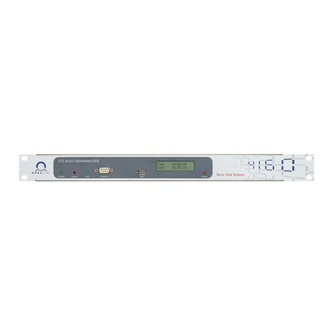
GPS RECEIVER
Model : T-GPS-300
Type : Micro Controller type
Display ; Backlit LCD display 24 Hours format
Time Accuracy : Better than 1 PPM
Input ; 1575.14 MHz from Antenna
Input Connector : BNC
Output : RS 232
1 PPS OUTPUT to Redundant
Master Clock
O/P Connectors : RS 232 / 1PPS – 9 Pin D Connector
Front Panel : LCD Display To show Required Data And
Status and number of satellites), valid data LED
Back Panel : 24 V input connector , Fuse, On/Off switch ,
RS 232 / 1 PPS output, 9 Pin ‘D’ connector,
Alarm contact terminal
Supply Voltage : 24V Supply from redundant Diode Oring unit
Environments : Temp. : 0-50 deg.cen
RH : Up to 95% non condensing
Mounting : To suit Standard 19” Rack System
Dimension : 2U (H) X 484 (W) X 325 (D)
`

6

7
05
MASTER CLOCK A & B-data
Model No. : T-MA-300
Type : Micro Controller based
Display : 7 segment LED(25mm size) to display TIME in HH,MM
and SS (24 Hrs. format) & in DD, MM and YY.
Time Reference : Oven Controlled Crystal Oscillator with stability of 1PPM
temperature range of 0-50 deg.c
Time Accuracy : Better than 1PPM
Time / Date Setting : Through Thumb wheel Switch Date / Time Toggle Switch
Inputs : a) 1PPS } From
RS232C } GPS Receiver
I/P Connectors : 'D' connector 9 pin for RS232 and 1 PPS
Outputs : Isolated output to Redundant comparator
Clock
O/P Connectors : 9 pin D connector for Signal output to Redundant
Comparator unit
Supply Voltage : 24V supply from Diode Oring unit
Environment : a) Temp. 0-50 Deg.C
b) RH 0-90% Non-condensing
Front Panel : Display, Toggle S/W (Date / Time),Thumb wheel Stn.)
Push Button S/W (ENTER),Lock S/W with Key
Back Panel : ON / OFF Switch, Fuse, Power Supply Terminals
Data output to comparator Terminal
Contact output terminals.
Panel Mounting : To suit Standard 19” Rack System
Dimension : 484mm (W) 2U (H) 325 mm(D)

8

9
06
REDUNDANT COMPARATOR UNIT-A & B Compressed in One Unit
Model No. : T-COM-300
Type : Micro Controller based
Display : No Display Only LED Indication
Time Reference :Oven Controlled Crystal Oscillator with stability of 1PPM
temperature range of 0-50 deg.c
Time Accuracy :Better than 1PPM
Time / Date Setting :Automatically Synchronized with Master A or B
Inputs :a) 1PPS }
b) RS232C } From Master Clock A & B
I/P Connectors : 9 pin “D”connector for Master A & B input
Outputs : a) RS 232 O/P to RS 232 Output Signal Conditioner
b) S,M,H,D pulse to Pulse output Signal Conditioner
c) IRIG B Output to IRIG B Signal Conditioner
d) Data (RS232) Output to TCP/IP, TCP-IP ON NTP Output
Signal Conditioner
e) Differential Pulse to Slave Clock/ Slave Distribution amp
f) Alarm Contact output for Master signal fail
O/P Connectors : a) 9 pin D connector for RS 232 o/p
b) BNC for IRIG B O/P
c) Mounting connector slave clock contact
S,M,H,D,Pulse output and Alarm Output
Supply Voltage : 24V DC supply from redundant Diode Oring unit.
Environment : a) Temp. 0-50 Deg.C
b) RH 0-90% Non-condensing
Front Panel : a) Master A & B input status INDICATION LED
Indication b) Master A & B(comparator) output Indication LED
c) Master A & B Input fail indication
d) Signal output indication
Back Panel : ON / OFF Switch, Fuse, Power Supply Terminals
All Input Output Contact terminals
Panel Mounting : To suit Standard 19” Rack System
Dimension : 484mm (W) 3U (H) 325mm(D)

10

11
07
SIGNAL CONDITIONER- FOR PULSE OUT & PFC OUTPUT
Model No. : T-SC-300
Type : Micro Controller based
Indication : LED INDICATOR FOR Pulse Input and Output
Inputs : S,M,H,D Pulse from Redundant Comparator Unit
I/P Connectors : Pulse input Through Terminal connector
Outputs : a) PFC OUTPUT USER SELECTABLE BY
SECOND,MINUTE,HOUR,DAY
USING SELECTOR SWITCH. Or Fixed Pulse Output
Contact Duration 50msec(to vary from 20 to 999 msec)
All pulses are isolated contact / Pulse output
b) Pulse output for Second, Minute, Hour, Day Pulse
Pulse Output Duration 50 msec
O/P Connectors : a) Mounting connector / BNC for all PFC contact output
Pulse output
Pulse contact duration 50 msec.
Supply Voltage : 24 DC V supply from Redundant diode oring
Environment : a) Temp. 0-50 Deg.C
b) RH 0-90% Non-condensing
Front Panel : LED INDICATORS FOR
Pulse Input & output LED Indicator.
Back Panel : ON / OFF Switch, Fuse, Power Supply Terminals
Pulse input terminal connector
PFC output terminal
Pulse Output BNC / Mounting connector.
PFC Contact output Selector Switch.
Panel Mounting : To suit Standard 19” Rack System
Dimension : 484mm (W) 2U (H) 325 mm (D)

12

13
08
SIGNAL CONDITIONER FOR RS 232 output
Model No. : T-SC-300
Type : TIME FORMATE
Display : LED INDICATORS FOR SIGNAL INPUT AND OUTPUTS
Inputs : RS 232 FROM Redundant Comparator Unit
I/P Connectors : 9 PIN “D” (M) CONNECTOR
Outputs : RS 232 Every minute / Every Second
O/P Connectors : RS 232 O/P 9 PIN “D” connectors
.
Supply Voltage : 24V supply from Diode Oring Unit
Environment : a) Temp. 0-50 Deg.C
b) RH 0-90% Non-condensing
Front Panel : LED INDICATORS FOR
RS 232 I/P AND RS 232 OUTPUT
Back Panel : ON / OFF Switch, Fuse, and Power Supply Terminals
1. RS 232 I/P CONNECTOR
2. RS 232 O/P CONNECTOR
Panel Mounting : To suit Standard 19” Rack System
Dimension : 484mm (W) 2U (H) 325 mm (D)

14
Other manuals for T-GPS-300
2
This manual suits for next models
10
Table of contents