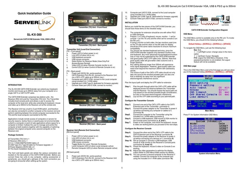
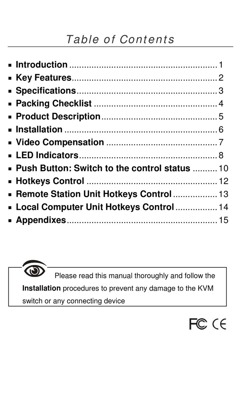
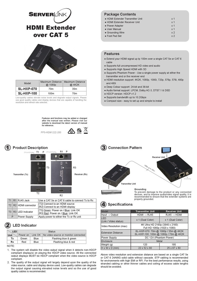
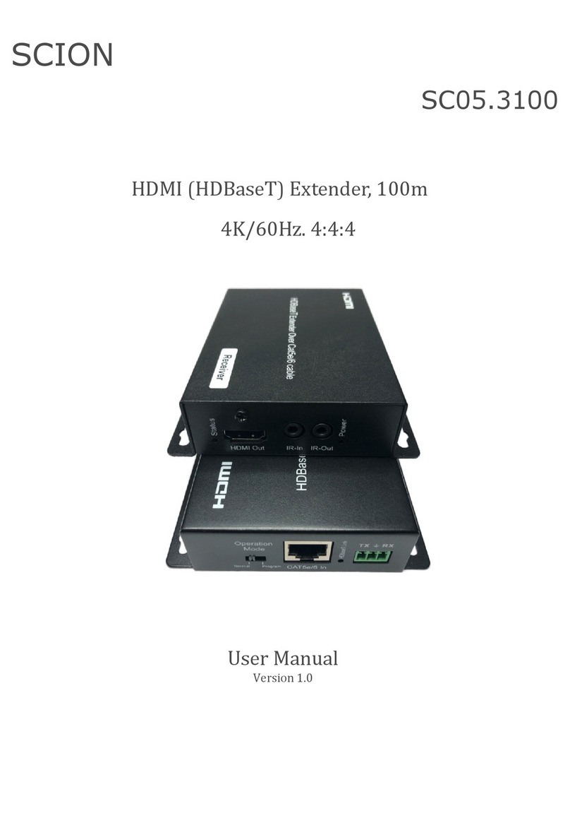
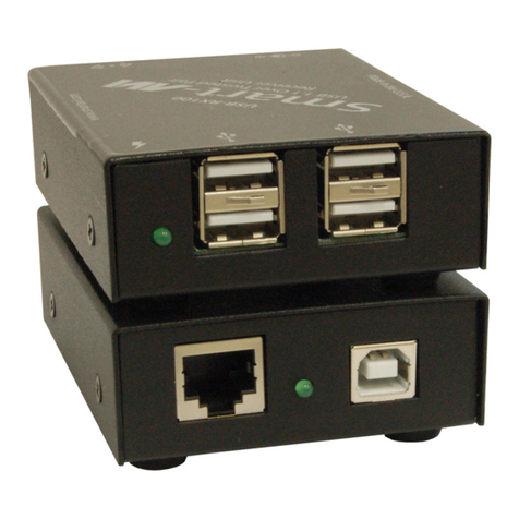
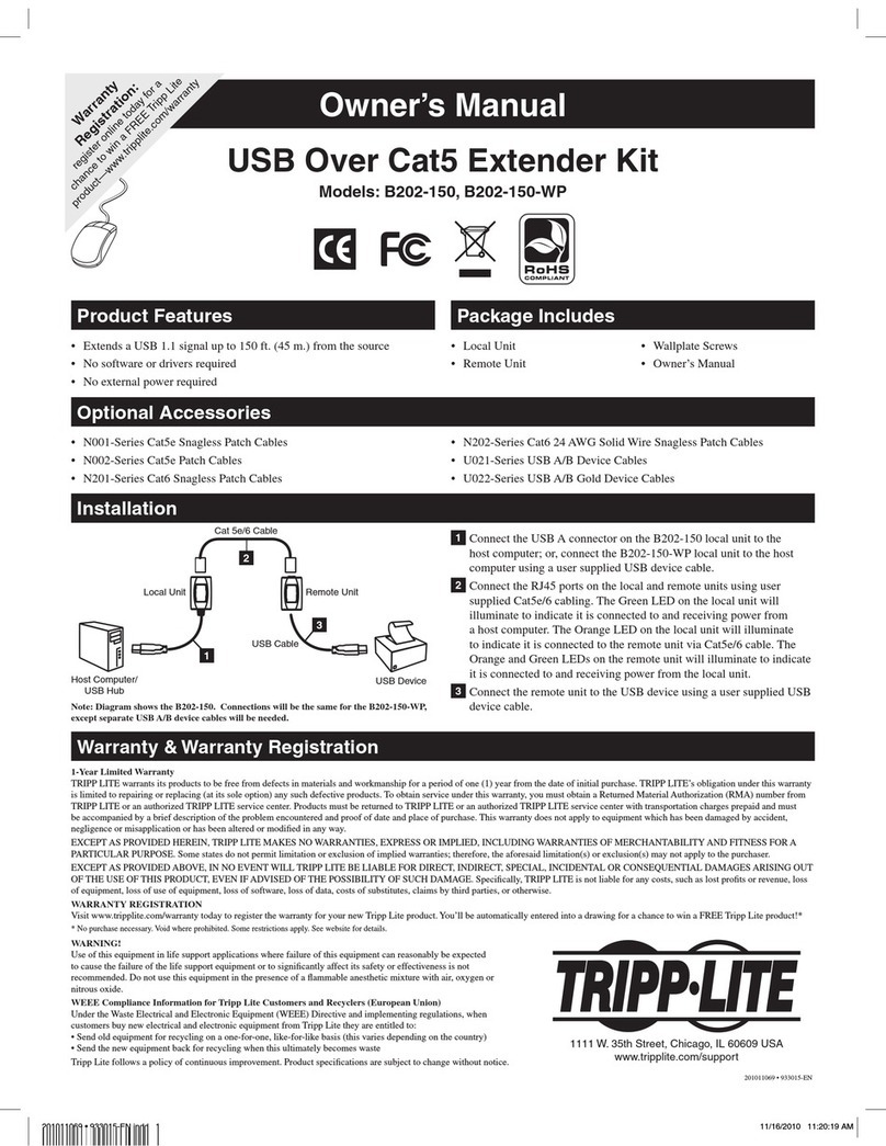
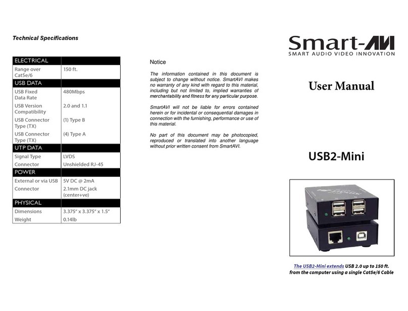
serverLink SL-DKAU-100 User manual

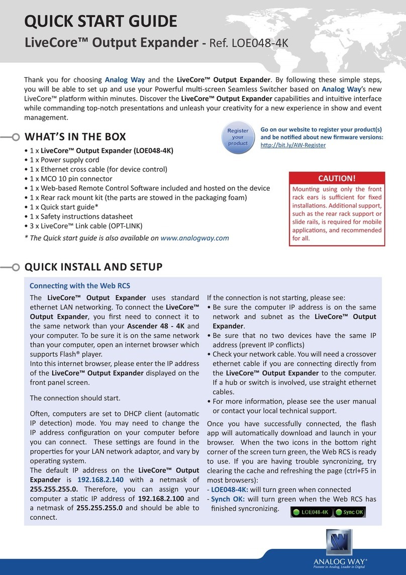
QuickInstallationGuideSL‐DKAU‐100DVIKVMExtenderoverIPorCAT5upto100m
1
Rev.1.1Copyright@AllRightsReserved
Quick Installation Guide
SL-DKAU-100
ServerLink DVI KVM Extender over IP or Cat 5
DVI, USB KB & Mouse, Audio & 2 x USB 2.0
Devices up to 100m
Transmitter (TX) Front View
Receiver (RX) Front View
Introduction
The SL-DKAU-100 DVI Extender over IP or Cat 5 can
extend your DVI monitor, USB keyboard, USB mouse,
audio and two other USB 2.0 devices such as an external
HDD, flash drive or printer up to 100m away from your
computer over a single CAT 5 or CAT 6 UTP cable.
You can connect the Transmitter unit directly to the
Receiver unit using a single inexpensive CATx UTP cable.
You can also use your existing cabling infrastructure and
connect via a standard Gigabit Ethernet Switch.
Since the DVI signal is interoperable with the HDMI
signal, you can use this DVI KVM Extender to extend
your HDMI display using optional DVI to HDMI
adapters.
Package Contents
Please check wand make sure you have all the following
items from the packaging box.
1 x Transmitter Unit (TX)
1 x Receiver Unit (RX)
1 x DVI-D Male to Male Cable
1 x USB Type A to Type B Cable
2 x Power Adapters (DC9V)
Front Panel & Back Panel
Transmitter (TX) Unit
Transmitter (TX) Unit Front View
Transmitter (TX) Unit Back View
Transmitter (TX) Unit Right Side View
[TX Front Panel]
a. Reset Button
b. Power LED (Lit when power is on)
c. Link LED (Lit when link is active)
d. Switch Button (Yellow – Sw1)
Short press to switch Remote Console ON/OFF
e. Switch Button (Yellow - Sw2)
Short press to select Graphic Mode/Video Mode
Long press to select Anti-Dither 1/2/OFF
f. RJ45 Port connect to the RX unit - 100m Maximum

QuickInstallationGuideSL‐DKAU‐100DVIKVMExtenderoverIPorCAT5upto100m
2
Rev.1.1Copyright@AllRightsReserved
[TX Back Panel]
g. Power Jack
h. USB Port (Type B)
i. IR Remote Output (Optional)
j. Microphone Connector
k. 3.5mm Audio Connector
l. DVI-D Input Port
m. 4 Position Dip Switch
n.
Receiver (RX) Unit
Receiver (RX) Unit Front View
Receiver (RX) Unit Back View
Receiver (RX) Unit Right Side View
1. Reset Button
2. Power LED (Lit when power is on)
3. Link LED (Lit when link is active)
4. Switch Button (Yellow Sw1)
Short press to switch Remote Console ON/OFF
5. Switch Button (Yellow Sw2)
Short press to select Graphic Mode/Video Mode
Long press to select Anti-Dither 1/2/OFF
6. USB 2.0 Port (TypeA) for keyboard or mouse
7. USB 2.0 Port (TypeA) for keyboard or mouse
8. USB 2.0 Device Port (Type A)
9. USB 2.0 Device Port (Type A)
10. RJ45 Port to connect to Receiver Unit
11. Power Jack
12. IR Remote Input (Optional)
13. Microphone Input
14. Audio Output
15. DVI-D Output
16. 4 Position Dip Switch
Pre-Installation
Before you install CAT5 DVI KVM Extender, you should
have these items on the checklist ready:
1. Prepare 1 set of keyboard, mouse & DVI monitor for
remote console (on RX).
2. You should use standard keyboards and mice, since
the CAT5 KVM extender supports only standard 5
button mice and keyboards. Any more advanced
mouse/keyboard function may or may not be
supported by this CAT5 DVI KVM extender.
3. Use good quality CATx UTP cable (max 100m).
Please Note: Good quality cable will give better video
outcome over a longer distance.
4. The choice of path of the CATx UTP cable should not
only take into account the shortest possible path, but
also one that is relatively far away from any significant
electromagnetic interference source.
5. If you need to extend the distance more than 100m,
you can use a Gigabit Ethernet Switch to serve as a
bridge and extend the distance an additional 100m.
6. There should be power outlets near where you locate
the extenders.
7. Plan the path through which the CATx UTP cable will
be deployed across the distance between the
Transmitter and the Receiver. You should choose the
layout path based on the shortest length and with the
least electromagnetic interference
If you already have a Gigabit Ethernet Network
installed, you can connect the Transmitter and
Receiver via your Gigabit Switch to utilize your existing
infrastructure. A 10/100Mbps network switch will suffer
undue latency and is therefore not recommended for
use.

QuickInstallationGuideSL‐DKAU‐100DVIKVMExtenderoverIPorCAT5upto100m
3
Rev.1.1Copyright@AllRightsReserved
Installation
Please Note: Before installation, ensure that the 4 Position
Dip Switch of the Transmitter and Receiver Units are set to
the same positions (The default setting for all switches is
ON)
Configure the Transmitter Unit
Step 1. Connect one end of the CATx UTP cable to the
CAT5 Extension port of the Transmitter.
(connector f)
Step 2. Connect the power adapter to the Transmitter to
power it up before connecting any computer or
cables to it. (connector g)
Step 3. Connect the Transmitter’s DVI port (connector i)
to the computer’s DVI output port using the
included DVI cable.
Step 4. Connect the Transmitter’s USB port (connector h)
to the computer’s USB port using the included
USB cable.
Step 5. Connect the speaker port (connector k) to the
audio out port of the computer
Step 6. Connect the microphone port (connector j) to the
microphone input port of the computer
Step 7. Power on the computer and make sure your local
DVI monitor is working before proceeding to the
next steps.
Configure the Receiver Unit
Step 8. Connect the other end of the CATx UTP cable to
the CAT5 Extension port of the Receiver.
(connector 10)
Step 9. Connect the power adapter to the Receiver
(connector 11) to power it up before connecting
any devices to it.
Step 10.Connect a DVI monitor to the DVI Output port.
(connector 15)
Step 11.Connect a USB keyboard and USB mouse to the
USB keyboard and mouse ports on the receiver.
You can connect to either port. (connectors 6 & 7)
Step 12.Connect a set of speakers (connector 14)
Step 13.Connect a microphone (connector 13)
Step 14.Connect two optional USB 2.0 devices such as an
external HDD, flash drive, printer, webcam etc.
(connectors 8 & 9)
Operation
To turn the Remote Console ON/OFF, Short press the Sw 1
button on either TX or RX.
According to your display contents, you can choose
either Graphic Mode or Video Mode to optimize the
video image on the Receiver unit. Graphic Mode is
best for still graphic images such as high definition
photos. Video Mode is best for dynamic display
contents such as movies and video clips that have fast
moving content.
To switch between Graphic Mode/Video Mode, Short press
the Sw 2 button on either TX or RX.
To switch between Anti-Dither 1/2/OFF, Long press the Sw
2 button on either TX or RX.
Trouble Shooting
Q: The resolution of display is reducing to 640 x 480 or
other settings other than 1920 x 1080
A: The monitor EDID should be automatically detected.
However if the connected monitor’s resolution is being
reduced, you may need to manually set the EDID. Please
follow the steps below to detect the EDID of connected
monitor. Note that this procedure is only available on
Receiver (RX) unit.
Step 1. Remove the power adapter from RX unit.
Step 2. Press and hold Sw2 and re-connect power adapter.
Step 3. Release the SW2 when the LED flashes red.
The monitor EDID should now be detected.
Other serverLink Extender manuals
