manuals.online logo
Brands
  1. Home
  2. •
  3. Brands
  4. •
  5. Servonaut
  6. •
  7. Transmitter
  8. •
  9. Servonaut AIR-U User manual

Servonaut AIR-U User manual

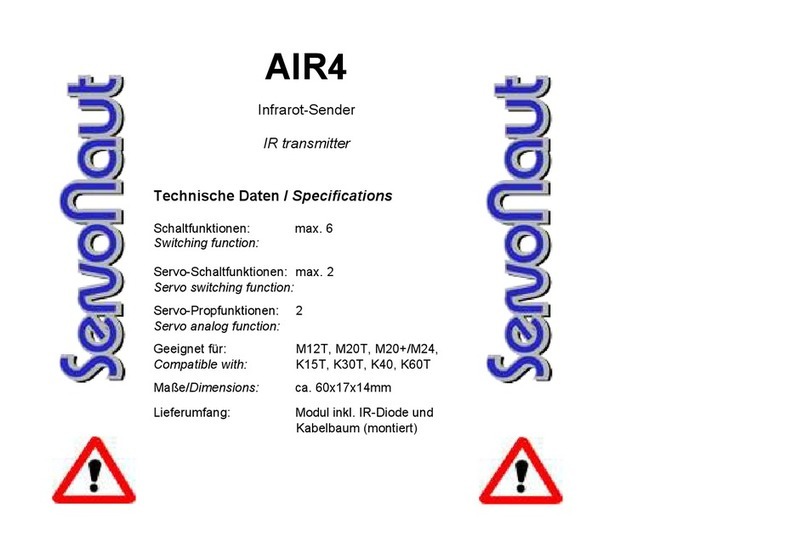
AIR-U
Infrarot-Sender
IR transmitter
Technische Daten / Specifications
Schaltfunktionen /
Switching functions: 6 (5 plus Servo)
Servo-Propfunktionen /
Servo analog function: 2
Benötigte Schaltsignale: Minus/ Masse
schaltend
Switching signals: signals must switch to -
Betriebsspannungen /
Operating voltage:
Empfänger / Receiver: 4,8 - 6 V
Schalteingänge für
Lichtanlagen / Light set 7,2 - 12 V
Maße / Dimensions: ca. 40x32x15mm
Funktionsumfang
Der Infrarot-Sender AIR-U überträgt
maximal 6 Schaltfunktionen (davon 1
Servo) und 2 Servo-Proportionalfunk-
tionen zu einem Infrarot-Empfänger der
Auflieger-Elektronik AMO. Er passt zu den
üblichen Multiswitch-Systemen und Licht-
anlagen mit nach Masse geschaltetem
Ausgang. Als Besonderheit kann der
Schalteingang „Function 6“ einen Servo
oder auch einen Fahrtregler am AMO-
Ausgang „Servo 4“ steuern. Der Eingang
„Stand/Side“ kann ein gedimmtes Signal
für Licht und Bremse erkennen und
steuert auch den Ausgang am AMO
entsprechend in zwei Helligkeiten. Zu-
sätzlich bietet der AIR-U zwei unab-
hängige Proportionalkanäle, mit denen
zwei Kanäle eines Fernsteuer-Emp-
fängers zu einem AMO übertragen
werden können.
Hinweis: Die Beschriftung der Eingänge
bezieht sich auf die Verwendung als Licht-
anlage, die Kombination aus AIR-U und
AMO ist aber universell einsetzbar.
Beliebige Schaltsignale können über-
tragen werden. Die Signale „Links/Left“,
„Rechts/Right“ und „Brems/Brake“ werden
ohne sichtbare Verzögerung übermittelt,
Features
The AIR-U transmits up to 6 switching
functions (including 1 Servo) and 2 analog
channels to the IR receiver of the trailer
module AMO. It is compatible with com-
mon multiswitch systems and light sets.
Special feature: The switching input
“Function 6” controls a servo or a speed
controller at AMO output “Servo 4”. The
input “Stand/Side” can process a dimmed
signal for combined light and brakes and
controls the output at the AMO accordingly
in two brightness levels. The AIR-U has
two analog channels to transmit from RC
receiver to AMO.
Please note: The inputs are labelled to
show how to use it as a light set but you
can use the AIR-U and AMO universally.
However you use them, the signals
„Links/Left“, „Rechts/Right“ and
„Brems/Brake“ are transmitted without de-
lay, the others may be delayed (but for
less than a second).
Mounting and connecting the AIR-U
The IR transmitter AIR-U is power sup-
plied by the receiver. If the light set is
powered by a second battery, its negative
pole must be connected to the negative
pole of the receiver supply. That is the
case with most common light sets.
2
Please note: Connect “Battery +” to the
positive pole of the light set or the multi-
switch. For Servonaut speed controller
S20, E20 and M212T, M220, Mini-Multi-
switch MM4 or Mini light set ML4: Connect
the screw terminals of the AIR-U with the
outputs of these modules (see labels).
For the light sets MFC-01, MFC-02 and
MFC-03: Connect the AIR-U to the cables
of the LEDs. Find a place for the AIR-U.
Look at the wiring table first, cut one wire
per LED cable accordingly so that both
stripped ends fit into the screw terminals of
the AIR-U. There is one exception: For the
MFC-01/-03 connect the ends of the black
cable wire of the cable J19/J14 for -03
separately to two screw terminals of the
AIR-U (see wiring table).
Important: MFC-01 and -03 have only one
LED for the reversing light. You have to
connect a second LED in series.
The AIRU has two servo cables labelled
“Servo 5” and “Servo 6”, which you can
connect to any free channels of the
receiver. These analog channel signals
are transmitted to the trailer light set AMO.
You can use them for servos or speed
controllers. Important: One of these servo
cables has to be connected to the RC
die anderen eventuell mit kurzer Verzö-
gerung (unter einer Sekunde).
Einbau und Anschluss
Der Infrarot-Sender AIR-U wird direkt vom
Empfänger mit Strom versorgt.
Wenn die verwendete Lichtanlage aus
einem getrennten, zweiten Akku versorgt
wird, muss der Minuspol dieses Akkus mit
dem der Empfängerstromversorgung
(BEC) verbunden sein. Bei gängigen Anla-
gen ist dies normalerweise der Fall.
Bitte beachten: Der Anschluss „Battery +“
wird mit dem Plusanschluss der jeweiligen
Lichtanlage bzw. des Multiswitch verbun-
den. Für Servonaut-Fahrtregler S20, E20
und M212T, M220 sowie den Mini-Mul-
tiswitch MM4 oder die Mini-Lichtanlage
ML4 gilt: Eingänge des AIR-U mit den
passenden Ausgängen (siehe Beschrif-
tung) dieser Module verbinden.
Bei den Anlagen MFC-01, MFC-02 und
MFC-03 erfolgt der Anschluss des AIR-U
direkt an den LED-Kabeln. Vor dem Ver-
drahten festlegen, wo der AIR-U montiert
werden soll, dann je LED-Kabel eine Ader
(welche, siehe Anschlusstabelle) zum
AIR-U passend durchtrennen, die beiden
3
receiver to power the AIR-U (even if you
don’t use the servo function). If there is no
free receiver channels, use a Y-cable.
Adjustments/Calibration
The infrared (IR) diode has a wide angle
beam. To ensure optimal IR transmission,
let the diode stick out a little bit (several
tenths of a millimetre). Don’t let the diodes
wires touch any metal and don’t run the
cable near the receiver antenna.
Alternatively the infrared beam can be
transmitted through a king pin with bore
hole. Mount the AMO receiver diode
above the king pin and the transmitter
diode below the fifth wheel coupling, so
that it beams through the bore hole. You
can mount the diode horizontal to save
space. Use a brass plate or white piece of
plastic for a better reflection (see picture
on the right).
entstandenen Kabelenden abisolieren und
beide in der angegebenen AIR-U-An-
schlussklemme verschrauben. Eine Aus-
nahme bei der MFC-01 und MFC-03: Die
Enden der schwarzen Ader des Kabels
J19/J14 für -03 werden getrennt an zwei
Schraubklemmen des AIR-U angeschlos-
sen (siehe Anschlusstabelle).
Wichtig: Bei den MFC-01/-03 wird im Ge-
gensatz zur MFC-02 nur eine LED für den
Rückfahrscheinwerfer verwendet. Damit
der AIR-U fehlerfrei funktioniert, muss bei
MFC-01/-03 ein zweiter Rückfahrschein-
werfer nachgerüstet werden. Schalten Sie
dazu eine zweite weiße LED in Serie.
Der AIR-U besitzt zwei Servokabel, mit
„Servo 5“ und „Servo 6“ beschriftet, die mit
freien Kanälen des Empfängers verbun-
den werden können. Die entsprechenden
Kanäle werden dann proportional zum
Aufliegermodul AMO übertragen und kön-
nen dort Servos oder Fahrtregler steuern.
Wichtig: Eines dieser Servokabel muss
mit dem Empfänger verbunden werden,
auch wenn die Servo-Funktion nicht ge-
nutzt werden soll. Nur so wird der AIR-U
mit Betriebsspannung versorgt. Sind be-
reits alle Kanäle am Empfänger belegt,
4
kann der Anschluss z.B. über ein V-Kabel
erfolgen.
Die Infrarot-Sendediode ist ein spezieller
Typ mit sehr breitem Abstrahlwinkel. Da-
mit eine optimale Abstrahlung möglich ist,
muss die Diode aus einer Befestigungs-
bohrung unbedingt einige 10tel Millimeter
herausragen und darf nicht versenkt mon-
tiert werden. Fixieren Sie die Diode mit
etwas Klebstoff. Die Anschlüsse dürfen
nicht mit Metallteilen in Berührung kom-
men. Wenn Sie durch eine Bohrung in
einem Königsbolzen übertragen und die
Sendediode dort montieren, spielt die Ab-
strahlung jedoch keine Rolle.
Hierfür montieren Sie die AMO Empfangs-
diode oberhalb des Königsbolzens und die
Sendediode unterhalb der Sattelplatte,
sodass sie direkt in die Bohrung strahlt
(siehe Schaubild). Um Platz zu sparen,
kann die Diode auch liegend montiert
werden. Sorgen Sie mit einem Stück
Messingblech oder weißem Kunststoff
dafür, dass ein Teil der Strahlen in die
Bohrung reflektiert wird.
Setup
With the jumper “Kombi” you adjust the
functionality of the input “Stand/Side”. If
the jumper is set, the AIR-U transmits only
on/off. Some light sets (e.g. Servonaut
M20+ in “Kombi” mode, Superlichtset
Truck, MFC-02) can also dim the rear light
for a combined rear and brake light. If the
jumper is removed the AIR-U will work with
these modules and the AMO will dim the
rear light accordingly.
Remove the jumper “Tam” only if you use
MFC-01/-03 (see wiring table).
5
Einstellungen
Die Steckbrücke „Kombi“ bestimmt die
Funktion des Eingangs „Stand/Side“. Bei
gesteckter Brücke erkennt der AIR-U nur
an/aus. Ohne Steckbrücke erkennt er
auch ein gedimmtes Signal dazwischen,
wie es bei Anlagen mit gemeinsamen
Lampen für Bremslicht und Rücklicht ver-
wendet wird (z.B. Servonaut M20+ im
Kombi-Modus, Superlichtset Truck, MFC-
02). Entsprechend steuert auch der AMO
zwei Helligkeiten am Ausgang „Standl./
Rear“.
Die Steckbrücke „Tam“ wird nur für die
Anlagen MFC-01 und -03 entfernt (siehe
Anschlusstabelle).
Anschlüsse
screw terminals
Steckbrücken
jumper
Anschluss für Pluspol der Lichtanlage
connect to light set positive pole
zur IR-Sendediode
to the IR diode
zwei Anschlusskabel
zum Empfänger
two receiver cables
6
Fahrtregler
ESC
AIR-U
Anschluss/
Steckbrücke
S20, E20, M212T,
M220 mit ML4
MFC-01/
(MFC-03)
MFC-02
Battery + ML4 “+” Tail Lamp J19 rot J18 gelb
Function
6
Frei für
Sonderfunktion
z.B. Fog Lamp
J17 schwarz
(J14 schwarz)
z.B. Fog Lamp
J20 grau
Rechts/
Right
ML4 “R” Winker/R/Right J23
blaues Kabel
J25B grün
Links/
Left
ML4 “L” Winker/R/Left J24
blaues Kabel
J26B grün
Rück/
Reverse
Regler
Rücklicht
Back Lamp J18
graues Kabel (*)
J17 grün
Brems/
Brake
Regler
Bremslicht
Nicht
verbinden
Nicht
verbinden
Stand/
Side
ML4 “1” Tail Lamp J19
schwarzes Kabel
zur LED gehend
J16 grau
Tam
MFC-01/
(MFC-03)
Nicht
verbinden
Tail Lamp J19
schwarzes Kabel
vom Stecker
Nicht verbinden
Tam
(jumper)
gesteckt entfernt gesteckt
Kombi
(jumper)
gesteckt gesteckt entfernt
AIR-U Anschlusstabelle
(*) siehe Hinweise unter Einbau und Anschluss
7
AIR-U
Anschluss/
Steckbrücke
Superlichtset MF
Hintere Platine
MVT-2000
Hinteres
Kabel
Battery + L + 2 rot
Function
6
z.B. L 3
Nebellampen
violett
Rechts/
Right
L 6 1 schwarz
Links/
Left
L 5 12 grau
Rück/
Reverse
L 4 7 blau
Brems/
Brake
Nicht
verbinden
3 gelb
Stand/
Side
L 2 9 grün
Tam
MFC-01
Nicht
verbinden
Nicht
verbinden
Nicht
verbinden
Tam
(jumper)
gesteckt gesteckt gesteckt
Kombi
(jumper)
entfernt gesteckt gesteckt
8
AIR-U
terminal/ jumper
S20, E20, M212T,
M220 with ML4
MFC-01/
(MFC-03)
MFC-02
Battery + ML4 “+” Tail Lamp J19 red J18 yellow
Function 6 Free for
special function
e.g. Fog Lamp
J17 black
(J14 black)
e.g. Fog
Lamp
J20 grey
Rechts/Right ML4 “R” Winker/R/Right J23
blue cable
J25B green
Links/Left ML4 “L” Winker/R/Left J24
blue cable
J26B green
Rück/Reverse control
reverse light
Back Lamp J18
grey cable (*)
J17 green
Brems/Brake control
brake light
Don’t
connect
Don’t
connect
Stand/Side ML4 “1” Tail Lamp J19 black
cable to LED
J16 grey
Tam
MFC-01/
(MFC-03)
Don’t
connect
Tail Lamp J19 black
cable from the Stecker
Don’t
connect
Tam
(jumper)
set removed set
Kombi
(jumper)
set set removed
(*) see chapter Mounting and Connecting
AIR-U wiring table
9
AIR-U
terminal/ jumper
Superlichtset MF
rear
circuit board
MVT-2000
rear connector
Battery + L + 2 red
Function 6 z.B. L 3 Fog
Lamp
purple
Rechts/Right L 6 1 black
Links/Left L 5 12 grey
Rück/Reverse L 4 7 grey
Brems/Brake Don’t
connect
3 yellow
Stand/Side L 2 9 green
Tam MFC-01/
(MFC-03)
Don’t
connect
Don’t
connect
Don’t
connect
Tam
(jumper)
set set set
Kombi
(jumper)
removed set set
10
11
Related Servonaut products
S20
Speed controller developed especially for
model trucks
20A, 16kHz, BEC 5V (3A peak)
Two outputs for reversing light and brake
light
ML4 and MM4
Small multiswitch modules for 4 functions
ML4 light set version, MM4 universal ver-
sion
AIR4, AIRU, AMO
Trailer lighting system with wireless infra-
red data transmission
Weitere Produkte von Servonaut:
S20
Speziell für den Funktionsmodellbau ent-
wickelter Fahrtregler
20A, 16kHz, BEC 5V (3A kurzzeitig)
Zwei Ausgänge für Brems- und Rück-
fahrlicht
ML4 und MM4
Mini-Multiswitch-Module für 4 Schaltfunk-
tionen
ML4 als Lichtanlage, MM4 universell ein-
setzbar
AIR4, AIRU, AMO
Anhänger/Auflieger-Lichtset mit draht-
loser IR Datenübertragung
12
Safety Notes
Do not expose the module to water
or oil. Do not cover it with foam.
Disconnect the battery immediately
after use. Do not connect the bat-
tery with wrong polarity. Avoid any
short circuits. Always use caution
when connecting the battery. Al-
ways turn on the transmitter first.
Warranty Information
Warranty is granted for one year
from date of purchase. This war-
ranty does not cover damage due
to incorrect handling or wiring, over
voltage or overloading. This war-
ranty does not cover consequen-
tial, incidental or collateral damage
under any circumstances. By the
act of using this product the user
accepts all resulting liability.
Subject to change without notice.
1/2013 Software V100
www.servonaut.de
Warnhinweise
Modul gegen Nässe, Feuchtigkeit und Schmutz
schützen. Nicht mit Schaumstoff umgeben, evtl.
entstehende Wärme muss abgeführt werden
können. Akku niemals verpolt anschließen. Kurz-
schlüsse unbedingt vermeiden. Akku nach dem
Betrieb und zum Laden immer von der Modell-
elektronik trennen.
Haftung und Gewährleistung
Es gelten die zum Zeitpunkt des Kaufs gültigen
gesetzlichen Bestimmungen zur Gewährleistung.
Vorausgesetzt ist der bestimmungs- gemäße Ge-
brauch im nichtgewerblichen Bereich. Schäden
durch unsachgemäße Behandlung wie fehler-
hafter Anschluss eines Akkus oder durch Wasser
sind ausgeschlossen, Eingriffe und Verände-
rungen lassen den Gewährleistungsanspruch
ebenfalls verfallen. Unsere Haftung bleibt in je-
dem Fall auf den Kaufpreis beschränkt. Die Haf-
tung für Folgeschäden ist ausgeschlossen.
Technische Änderungen vorbehalten. “Servo-
naut” ist eine eingetragene Marke der tematik
GmbH. Alle weiteren Produktnamen, Warenzei-
chen und Firmennamen sind Eigentum ihres je-
weiligen Besitzers.
1/2013 Software V100
tematik GmbH
Feldstrasse 143
22880 Wedel
Germany
Fon: +49 (0) 4103 80 89 89 - 0
Fax: +49 (0) 4103 80 89 89 - 9
E-mail: [email protected]
Internet: www.servonaut.de
Ein wichtiger Hinweis zum
Umweltschutz:
Elektro- und Elektronik-Altgeräte gehören
nicht in den Hausmüll!
Entsorgen Sie bitte diese Geräte bei den
kommunalen Sammelstellen. Die Abgabe
dort ist kostenlos.
Help us to protect the environment.
Please do not dispose electrical and elec-
tronic equipment in domestic household
waste.
tematik GmbH - Servonaut
WEEE-Reg.-Nr. DE 76523124

Other Servonaut Transmitter manuals

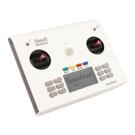
Servonaut AIR4 User manual

Servonaut

Servonaut AIR4 User manual

Servonaut ServoNaut Radio Zwo4 HS16 User manual

Servonaut

Servonaut ServoNaut Radio Zwo4 HS16 User manual

Popular Transmitter manuals by other brands

Vishay Nobel WST 3 Operating instructions, quick installation

Vishay Nobel

Vishay Nobel WST 3 Operating instructions, quick installation

Siemens SITRANS TF2 quick start guide

Siemens

Siemens SITRANS TF2 quick start guide

Levil Aviation Beacon 978 Series Installation and Pilot's Guide

Levil Aviation

Levil Aviation Beacon 978 Series Installation and Pilot's Guide

Vaisala HUMICAP HMT140 quick guide

Vaisala

Vaisala HUMICAP HMT140 quick guide

Hyundai FMT 350 CHARGE instruction manual

Hyundai

Hyundai FMT 350 CHARGE instruction manual

ARMANO HART B74 operating instructions

ARMANO

ARMANO HART B74 operating instructions

M-system M3SMS instruction manual

M-system

M-system M3SMS instruction manual

Spacelabs Healthcare AriaTele 96281 quick start guide

Spacelabs Healthcare

Spacelabs Healthcare AriaTele 96281 quick start guide

Emerson Rosemount 644h quick start guide

Emerson

Emerson Rosemount 644h quick start guide

Siemens SITRANS P MK II Series instruction manual

Siemens

Siemens SITRANS P MK II Series instruction manual

Warner RF FMT-80D Operation user's manual

Warner RF

Warner RF FMT-80D Operation user's manual

FONESTAR FO-459-TX instruction manual

FONESTAR

FONESTAR FO-459-TX instruction manual

Inovonics EN1210 installation instructions

Inovonics

Inovonics EN1210 installation instructions

Nautel VS2.5 installation manual

Nautel

Nautel VS2.5 installation manual

Bauer 707 Assembly instructions

Bauer

Bauer 707 Assembly instructions

Mateksys Video Transmitter 5.8G VTX-mini quick start guide

Mateksys

Mateksys Video Transmitter 5.8G VTX-mini quick start guide

FSR TWISTER MMTP-100 operating instructions

FSR

FSR TWISTER MMTP-100 operating instructions

Thies CLIMA 4.3515.30.000 Instructions for use

Thies CLIMA

Thies CLIMA 4.3515.30.000 Instructions for use

manuals.online logo
manuals.online logoBrands
  • About & Mission
  • Contact us
  • Privacy Policy
  • Terms and Conditions

Copyright 2025 Manuals.Online. All Rights Reserved.