HART VPT10-H Quick guide

INSTALLATION, OPERATION, CONFIGURATION AND MAINTENANCE MANUAL
July/2020
VPT10-H
HART® PRESSURE TRANSMITTER

VPT10-H HART
®
PRESSURE TRANSMITTER INSTALLATION, OPERATION, CONFIGURATION AND MAINTENANCE MANUAL
____________________________________________________________________________________________________________________________
2
COPYRIGHT
All rights reserved, including translations, reprints, complete or partial reproduction of this manual, patent
concession or model register of use/project.
No part of this publication may be reproduced, copied, processed or transmitted on any manner or any medium
(photocopy, scanning, etc.) without the express permission of Vivace Process Instruments Inc., not even for
training or electronic systems.
HART
®
is a registered mark of HART Communication Foundation.
NOTE
We have reviewed this manual with great care to maintain compliance with the hardware and software versions
described herein. However, due to the dynamic development and version upgrades, the possibility of technical
deviations cannot be ruled out. We cannot accept any responsibility for the full compliance of this material.
Vivace reserves the right to, without notice, make modifications and improvements of any kind in its products
without incurring in any circumstances, the obligation to make those same modifications to products sold
previously.
The information in this manual is frequently updated. Therefore, when using a new product, please check the
latest version of the manual on the Internet through our website www.vivaceinstruments.com, where it can be
downloaded.
You customer is very important for us. We will always be grateful for any suggestions for improvements as well
as new ideas, which can be sent to the e-mail: contato@vivaceinstruments.com preferably with the title
"Suggestions".

VPT10-H HART
®
PRESSURE TRANSMITTER INSTALLATION, OPERATION, CONFIGURATION AND MAINTENANCE MANUAL
____________________________________________________________________________________________________________________________
3
SUMMARY
1EQUIPMENT DESCRIPTION..................................................................................................................................6
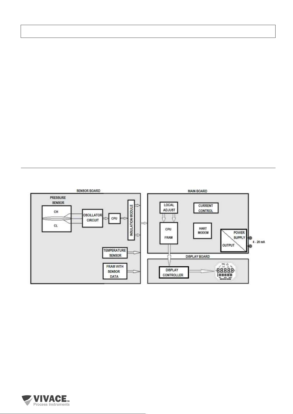
1.1. BLOCK DIAGRAM.........................................................................................................................................6
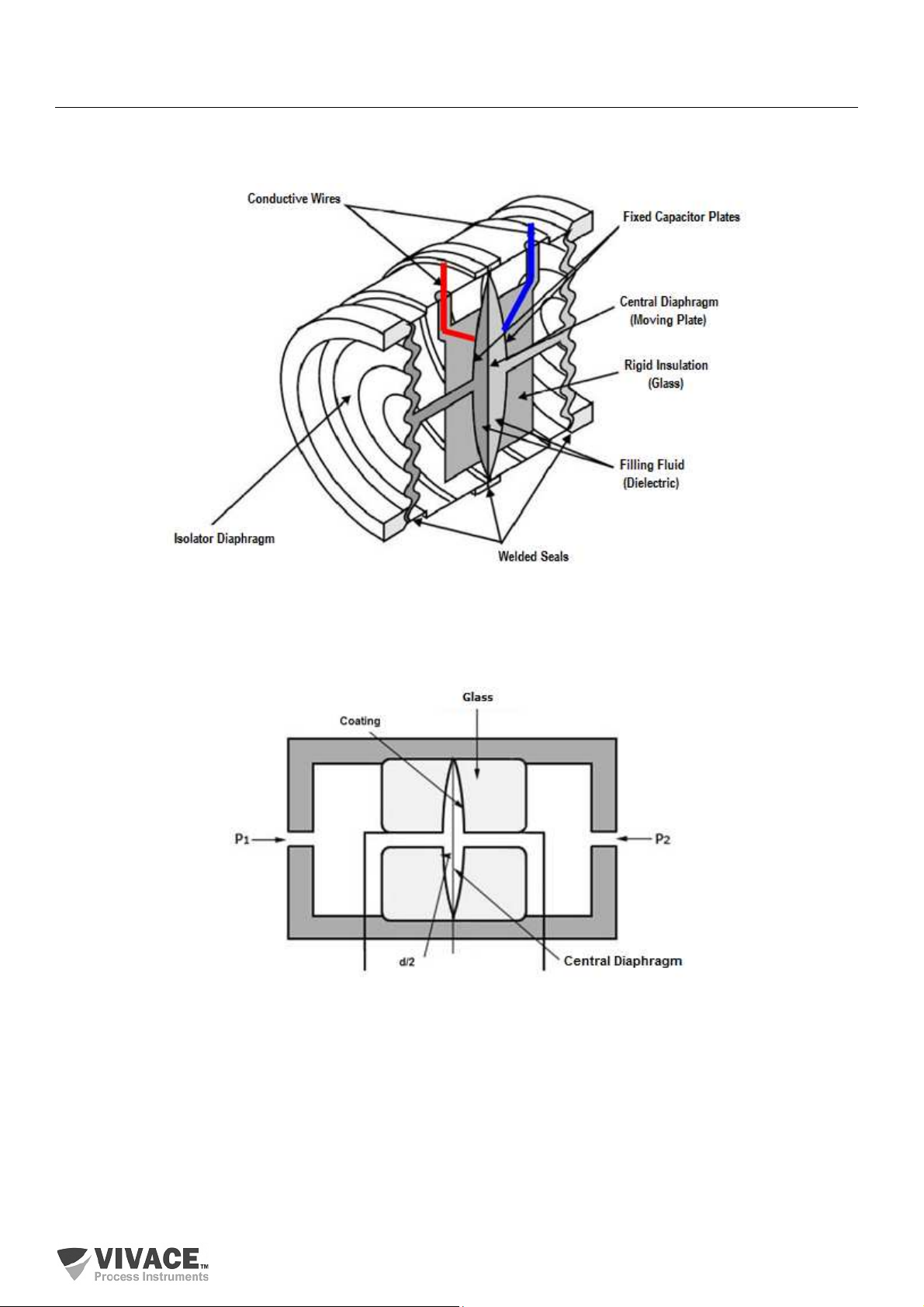
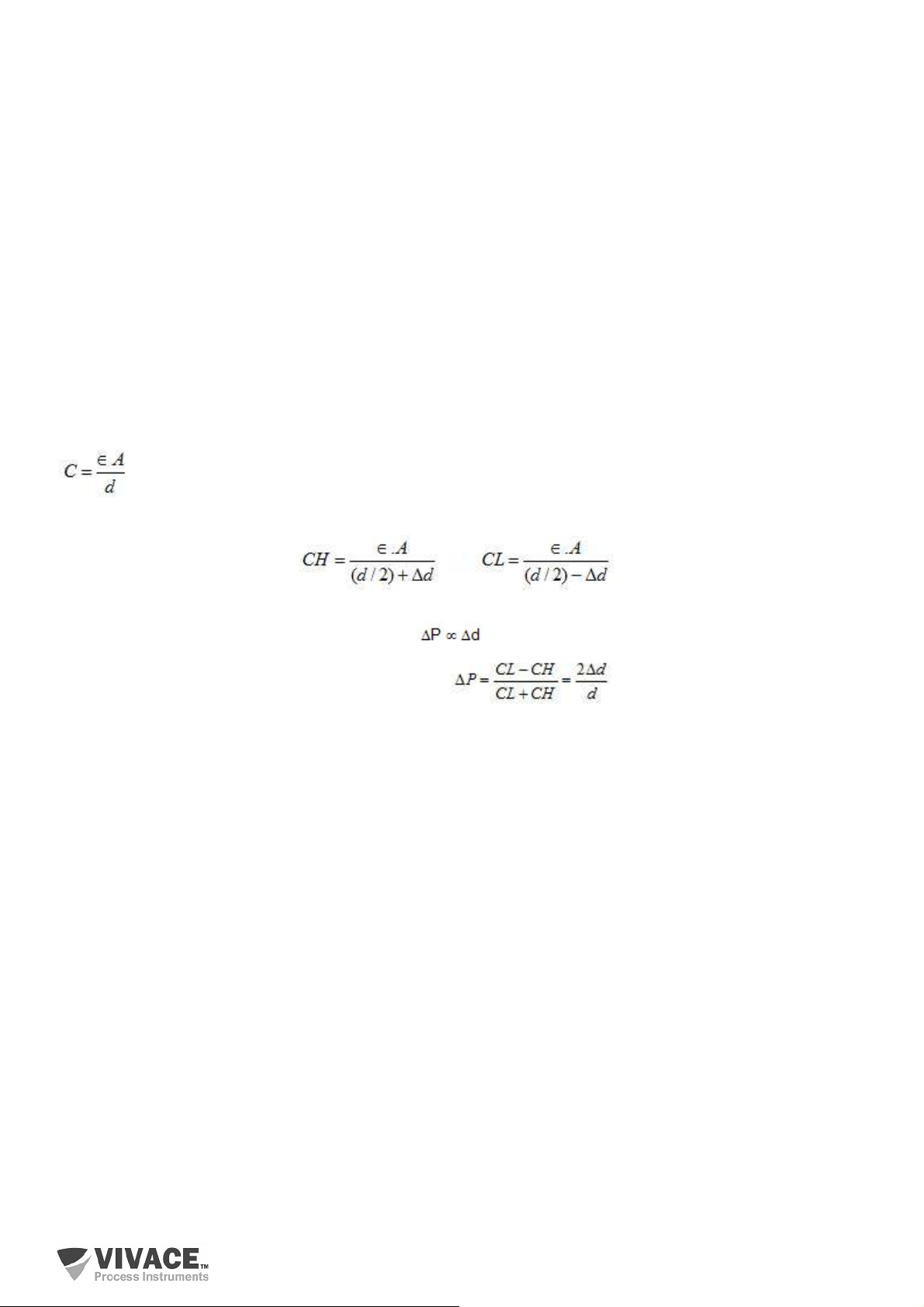
1.2. CAPACITIVE SENSOR .................................................................................................................................7
1.3. OPERATING PRINCIPLE..............................................................................................................................9
2INSTALLATION ....................................................................................................................................................10
2.1. MECHANICAL ASSEMBLY.........................................................................................................................11
2.2. ELECTRICAL CONNECTION .....................................................................................................................14
3CONFIGURATION ................................................................................................................................................16
3.1. LOCAL CONFIGURATION..........................................................................................................................16
3.2. JUMPER CONFIGURATION FOR LOCAL ADJUST AND WRITE PROTECTION ....................................17
3.3. LIQUID CRYSTAL DISPLAY (LCD) ............................................................................................................18
3.4. HART
®
PROGRAMMER..............................................................................................................................18
3.5. LOCAL ADJUST CONFIGURATION TREE ................................................................................................20
3.6. HART CONFIGURATOR PROGRAMMING TREE .....................................................................................21
3.7. CALIBRATION .............................................................................................................................................25
3.8. DIAGNOSIS .................................................................................................................................................26
3.9. FDT/DTM CONFIGURATION......................................................................................................................28
4MAINTENANCE ....................................................................................................................................................29
4.1. ASSEMBLY AND DISASSEMBLY PROCEDURES....................................................................................29
4.2. SPARE PARTS............................................................................................................................................30
5CERTIFICATION ...................................................................................................................................................32
6TECHNICAL CHARACTERISTICS ......................................................................................................................33
6.1. IDENTIFICATION ........................................................................................................................................33
6.2. TECHNICAL SPECIFICATION....................................................................................................................34
6.3. ORDERING CODE ......................................................................................................................................35
7WARRANTY..........................................................................................................................................................38
7.1. GENERAL CONDITIONS ............................................................................................................................38
7.2. WARRANTY PERIOD .................................................................................................................................38
APPENDIX ....................................................................................................................................................................39

VPT10-H HART
®
PRESSURE TRANSMITTER INSTALLATION, OPERATION, CONFIGURATION AND MAINTENANCE MANUAL
____________________________________________________________________________________________________________________________
4
It is extremely important that all the safety instructions, installation and operation in this manual are followed
faithfully. The manufacturer is not liable for damage or malfunction caused by improper use of this equipment.
It is recommended to strictly following the rules and good practice relating to installation, ensuring correct
grounding, noise insulation and good quality cables and connections in order to provide the best performance
and durability to the equipment.
Special attention must be considered in relation to installations in hazardous areas, where applicable.
•Appoint only skilled people, trained with process and equipment;
•Install equipment only in operation compatible areas, with the proper connections and protections;
•Use proper safety equipment for any handling device in field;
•Turn area power off before equipment installation.
SAFETY PROCEDURES
SYMBOLOGY
Caution - indicates risk or error source
Important Information
General or Specific Risk
Electric Shock Danger
WARNING

VPT10-H HART
®
PRESSURE TRANSMITTER INSTALLATION, OPERATION, CONFIGURATION AND MAINTENANCE MANUAL
____________________________________________________________________________________________________________________________
5
GENERAL INFORMATION
Vivace Process Instruments ensures the operation of this equipment, according to the descriptions
contained in its manual, as well as technical characteristics, not guaranteeing its full performance in
particular applications.
The operator of this equipment is responsible for observing all aspects of safety and prevention of
accidents applicable during the execution of the tasks in this manual.
Failures that might occur in the system, causing damage to property or injury to persons, shall
additionally be prevented by external means to a safe outlet for the system.
This equipment must be used only for the purposes and methods proposed in this manual.

VPT10-H HART
®
PRESSURE TRANSMITTER INSTALLATION, OPERATION, CONFIGURATION AND MAINTENANCE MANUAL
____________________________________________________________________________________________________________________________
6
1 EQUIPMENT DESCRIPTION
VPT10-H is a transmitter for differential, absolute or gauge pressure, level or flow measurements with HART
®
technology, which integrates Vivace Process Instruments family of field devices.
The transmitter features intelligent, microprocessor-based capacitive sensor for safe operation and excellent field
performance. It has integrated pressure and temperature compensations, providing high performance and stability
of measurements.
VPT10-H must be powered by a voltage of 12 to 45 Vdc in order to generate a 4-20 mA current channel (according
to NAMUR NE43) proportional to the measurement performed.
Its configuration uses HART
®
7 communication protocol, already recognized as the most used in the world of
industrial automation for configuration, calibration, monitoring and diagnostics, and can be performed by the user
with the use of a HART
®
configurator or EDDL
®
or FDT/DTM
®
-based tools. In addition, the main parameters can be
set via local adjustment using a magnetic tool.
VPT10-H intelligent pressure transmitter is factory calibrated before shipment to customers. If it is necessary to
recalibrate this transmitter in the field, be sure to use a calibrator at least three times more accurate than the
specifications. To ensure correct and efficient use of the transmitter, please read this manual before installation.
1.1. BLOCK DIAGRAM
The modularization of the transmitter components is described in the following block diagram.
Figure 1.1 –VPT10-H block diagram.
The main board controls the main functions of the pressure transmitter. It contains a HART
®
Modem and a
microcontroller (CPU). The sensor board is responsible for reading the capacitance of the capacitive sensor, as well
as the temperature and its processing with the main CPU.
The HART
®
modem block interfaces the microcontroller signals with the HART
®
line to which the transmitter connects.
The display board has the controller block that interfaces between the LCD and the CPU, adapting the messages to
be displayed.
Finally, the microcontroller block can be related to the transmitter's brain, which manages all the time controls, HART
®
state machines, diagnostics and routines common to transmitters, such as configuration, calibration and generation of
the digital output value for current, proportional to the PV variable.

VPT10-H HART
®
PRESSURE TRANSMITTER INSTALLATION, OPERATION, CONFIGURATION AND MAINTENANCE MANUAL
______________________________________________________________________________________________________________________________
7
1.2. CAPACITIVE SENSOR
The pressure sensor used by VPT10-H pressure transmitter is capacitive (capacitive cell), shown schematically in
figure 1.2.
Figure 1.2 – High performance capacitive sensor.
See figure 1.3, below, to understand the working principle of the capacitive sensor.
Figure 1.3 – Principle of operation of the capacitive sensor.
The core of the capacitive sensor is the central diaphragm. There are two measuring capacitances (CH and CL),
according to the position of this diaphragm. These measuring capacitances share the central diaphragm (movable
plate) and the other plate is attached to both sides of the sensor.
When the pressures on both sides are equal, the diaphragm is in the center and the capacitances on both sides are
the same. However, when the pressure on the high pressure side (CH) is greater than the pressure on the low pressure
side (CL), for example, the filling fluid will move, causing the diaphragm to move to the low pressure side . As a result,
the capacitance on the high pressure side will be lower than the capacitance on the low pressure side.

VPT10-H HART
®
PRESSURE TRANSMITTER INSTALLATION, OPERATION, CONFIGURATION AND MAINTENANCE MANUAL
______________________________________________________________________________________________________________________________
8
However, when the differential capacitance structure is used, the distance between CL and CH plates has a linear
variation with the relation between the difference and the sum of the measured capacitances.
When the displacement of the central diaphragm is inferior than its thickness, there will be a linear relationship between
this displacement and the differential pressure. That is, if the differential pressure (∆P) applied to the capacitive cell
does not deflect the sensor diaphragm beyond d/4, we can assume that ∆P will be proportional to ∆d.
In short:
P1 and P2 are applied pressures on the high and low pressure sides (H and L), respectively.
CH = capacitance on high pressure side, measured between P1 fixed plate and the central diaphragm.
CL = capacitance on low pressure side, measured between P2 fixed plate and the central diaphragm.
d = distance between the fixed plates of CH and CL.
∆d = deflection of the central diaphragm due to the application of the differential pressure ∆P = P1 - P2.
The capacitance of a capacitor of flat and parallel plates can be expressed as a function of the area (A) of the plates
and the distance (d) separating them as:
, where ϵ= the dielectric constant of the medium between the capacitor plates.
If we consider CH and CL as capacitances of flat plates of the same area and parallel, when P1> P2 we have:
On the other hand, if the differential pressure (∆P) applied to the capacitive cell does not deflect the sensor diaphragm
beyond d/4, we can assume ∆P proportional to ∆d.
If we develop the expression (CL-CH) / (CL+CH) we get:
As the distance (d) between the fixed plates of CH and CL is constant, the expression (CL-CH) / (CL+CH) is
proportional to Δd and therefore to the differential pressure to be measured.
Thus, it is concluded that the capacitive cell is a pressure sensor composed of two capacitors of variable capacitances,
according to the applied differential pressure.
These capacitors are part of an oscillator circuit that has its frequency dependent on the applied differential pressure.
This frequency will be inversely proportional to the applied pressure and is measured by the CPU of the pressure
sensor with high resolution, accuracy and processing speed.

VPT10-H HART
®
PRESSURE TRANSMITTER INSTALLATION, OPERATION, CONFIGURATION AND MAINTENANCE MANUAL
______________________________________________________________________________________________________________________________
9
1.3. OPERATING PRINCIPLE
The main circuit of VPT10-H receives the capacitance readings (CL and CH) and temperature from the analog sensor
board. The normalized pressure signal is calculated by applying the factory compensation polynomial to the CL and
CH readings. From this value, using the sensor reading range, the pressure in the user unit (configurable) is calculated
with the relevant calibrations of zero, maximum pressure and minimum pressure.
Depending on the sensor range, user can choose the form of treatment for the pressure value: Linear, Table, Square
Root Extraction (single, triple or quintuple) or the combination between Table and Square Root Extraction. With the
option of Table, it is possible to mount a custom curve of up to 16 points, mainly used with the characterization of
volumes in tanks. The Square Root Extraction is used in the application of the mass and flow measurement transfer
function.
Figure 1.4 – Operating principle of VPT10-H.
VPT10-H still provides the ambient temperature reading as a secondary variable and the pressure reading as a tertiary
variable (even if the primary variable is set as flow measurement).
The primary variable (PV) can be configured to indicate pressure or flow according to the configured transfer function
(Linear and Table for Pressure, Square Root Extraction for Flow).
According to the type of variable to be indicated, user can also configure unit, work range, limits and alarms (for
pressure and flow, separately).
In addition, the transmitter can calculate the Totalization, considering the flow rate, according to the unit configured by
user (mass or volume in time). It is possible to reset the Totalization, enable/disable it and also set a limit value so an
alarm can be generated.

VPT10-H HART
®
PRESSURE TRANSMITTER INSTALLATION, OPERATION, CONFIGURATION AND MAINTENANCE MANUAL
______________________________________________________________________________________________________________________________
10
2 INSTALLATION
RECO
M
MENDA
TION
When taking the equipment to the installation location, transfer it in the original packaging. Unpack the
equipment at the installation location to avoid damage during transportation.
RECO
M
MENDA
TION
Model and specification of equipment are indicated on identification plate, located at the top of the
housing. Check if supplied specification and model correspond to application requirements. Be aware of
the maximum and minimum specifications and sensor range. After installation in the field, see Calibration
topic.
STORAGE
The following precautions should be observed when storing the equipment, especially for a long period:
(1) Select a storage area that meets the following conditions:
a) No direct exposition to rain, water, snow or sunlight.
b) No exposition to vibration and shocks.
c) Normal temperature and humidity (around 20°C / 70°F, 65% RH).
However, it can also be stored under the following temperature and humidity intervals:
●Ambient Temperature: -40°C to 85°C (without LCD)* or -30°C to 80°C (with LCD)
●Relative Humidity: 5% to 98% RH (@ 40°C)
(2) For equipment storage, use original factory package (or similar).
(3) If storing an already used Vivace equipment, dry every moist part and clean all connections that
was in contact with the process. Keep covers and connections closed and properly protected for its
specific application and requirements.
* Only for general use. For explosion proof version, follow product certification requirements.

VPT10-H HART
®
PRESSURE TRANSMITTER INSTALLATION, OPERATION, CONFIGURATION AND MAINTENANCE MANUAL
______________________________________________________________________________________________________________________________
11
2.1. MECHANICAL ASSEMBLY
VPT10-H transmitter is designed for field installation and thus supports weather exposure, having good performance
with variations in temperature, humidity and vibration.
Its housing has an IP67 degree of protection, being immune to water entering its electronic circuit and terminal block,
provided that the cable gland or conduit of the electrical connection is correctly assembled and sealed with non-
hardenable sealant. The covers should also be tightly closed to prevent moisture entering, as the threads of the housing
are not protected by paint.
The electronic circuit is coated with a moisture-proof varnish, but constant exposures to moisture or corrosive media
can compromise its protection and damage electronic components.
Figure 2.1 shows the dimensional design and mounting forms of the VPT10-H.
Figure 2.1 –Dimensional drawing and mounting for VPT10-H.

VPT10-H HART
®
PRESSURE TRANSMITTER INSTALLATION, OPERATION, CONFIGURATION AND MAINTENANCE MANUAL
______________________________________________________________________________________________________________________________
12
In order to avoid risk of the VPT10-H covers being released unintentionally due to vibrations, for example, they can be
locked by means of a screw, as shown in figure 2.2.
VPT10-H is a field device that can be installed through a bracket in a 2" tube holded by a U-clamp. For best LCD
positioning the equipment can rotate 4 x 90°, as shown in figure 2.3 . The transmitter can also be fixed with the same
bracket on wall or panel.
Figure 2.2 – Front cover lock.
Figure 2.3 – Housing position adjustment.
The LCD liquid crystal display of VPT10-H can be rotated 4 x 90° so that the display is as adequate as possible for
easy user viewing.
Figure 2.4 illustrates the possible rotation for VPT10-H LCD.
Figure 2.4 –4 x 90° LCD rotation.

VPT10-H HART
®
PRESSURE TRANSMITTER INSTALLATION, OPERATION, CONFIGURATION AND MAINTENANCE MANUAL
______________________________________________________________________________________________________________________________
13
VPT10-H pressure transmitter is designed to withstand harsh environmental conditions. However, to ensure stable
and accurate operation for a long time, the following precautions must be observed when selecting an installation
location.
(1) Ambient Temperature
VPT10-H has an intrinsic algorithm to compensate temperature variations. In the production process each transmitter
is subjected to several cycles of temperature and a polynomial is created in order to minimize temperature variation,
ensuring high performance of pressure measurements at any temperature. However, it is recommended to avoid
locations subject to large variations in temperature or temperature gradients. If the site is exposed to radiant heat,
provide adequate thermal insulation or ventilation. Also, facilities where process fluid can freeze inside the transmitter
chamber should be avoided, which could cause permanent damage to the capacitor cell.
(2) Atmospheric Conditions
Avoid installing the transmitter in a corrosive atmosphere. If necessary, provide adequate measures to prevent or
minimize intrusion/stagnation of rainwater or condensation that may accumulate through the electrical input. In
addition, proper precautions should be taken in regard to corrosion due to condensation or moisture at the terminal
block. Inspect it regularly, checking for proper closure of its covers. The covers must be completely closed manually
until the o-ring is compressed, ensuring complete sealing. Avoid using tools in this operation. Be careful not to remove
housing covers in the field, as each opening introduces more moisture to the circuits.
(3) Shock and Vibration
Select an installation location subject to minimum shocks and vibrations. Although the transmitter is designed to be
relatively resistant and insensitive to vibration, it is recommended to follow good engineering practice. Mounts close to
pumps, turbines or other equipment that generate excessive vibration should be avoided. If vibration is unavoidable,
install the transmitter on a solid base using flexible hoses that do not transmit vibration.
(4) Installation of Transmitters with Explosion Proof Certification
Transmitters with this certification must be installed in hazardous areas according to the classification of the area for
which they are certified. Installations in classified areas should follow the recommendations of standard
NBR/IEC60079-14.
(5) Accessibility
Always select a location that provides easy access to the transmitter for maintenance and/or calibration. If so, rotate
the LCD for proper viewing.
When the measured fluid contains suspended solids, install valves at regular intervals to clean the tubing (discharge).
Clean pipes internally (using steam or compressed air) or drain the line with the process fluid itself, whenever possible,
before connecting these lines to the pressure transmitter.
Do not allow steam to enter the measuring chamber. Close the valves well after each drain or discharge operation.

VPT10-H HART
®
PRESSURE TRANSMITTER INSTALLATION, OPERATION, CONFIGURATION AND MAINTENANCE MANUAL
______________________________________________________________________________________________________________________________
14
Some examples of assemblies, showing the location of the transmitter relative to the taps, are shown in figure 2.5. The
location of the pressure taps and the relative position of the transmitter are shown in table 2.1.
Process Fluid Taps Location VPT10-H Location in relation to the Taps
Gas Superior or Lateral Above
Liquid Lateral Below or at same level
Steam Lateral Below using condensation chamber
Table 2.1 – Location of pressure taps.
Figure 2.5 – Examples for transmitter mounting, in relation to pressure taps.
2.2. ELECTRICAL CONNECTION
To access the terminal block, remove the rear cover of VPT10-H. To do this, loosen the cover locking screw (see figure
2.6) by turning it clockwise.
Figure 2.6 – Rear cover lock.

VPT10-H HART
®
PRESSURE TRANSMITTER INSTALLATION, OPERATION, CONFIGURATION AND MAINTENANCE MANUAL
______________________________________________________________________________________________________________________________
15
Figure 2.7 shows the power terminals (PWR BUS), the ground terminals (one internal and one external), in addition to
the communication and test terminals. To power the equipment it is recommended to use twisted-pair 22 AWG.
Table 2.2 describes the functions of the VPT10-H.
Figure 2.7 – Connections for VPT10-H. Table 2.2 – Terminal description for VPT10-H.
NOT
E
All cables used to connect the VPT10-H to the HART
®
network must be shielded to avoid interference
and noise.
The conduits through which the power cables of the equipment pass must be mounted in such a way as to prevent
water from entering the terminal block. The threads of the conduits must be sealed according to the standards required
by the area. The unused electrical connection must be sealed with a suitable plug and sealant.
Figure 2.8 shows the correct way to install the conduit in order to avoid the entrance of water or other product that
could cause damage to the equipment.
Figure 2.8 – Conduit installation.
Terminal Description
Power Terminals - PWR BUS
24 Vdc without polarity (12 to 45 Vdc)
Grounding Terminals
1 internal and 1 external
Test Terminals - TEST
4-20 mA measurement without circuit opening
Communication Terminals - COMM
Communication with HART
®
Configurator
NOTE
It is extremely important to ground the equipment for complete eletromagnetic protection and also to
ensure the correct performance of transmitter on the HART network.

VPT10-H HART
®
PRESSURE TRANSMITTER INSTALLATION, OPERATION, CONFIGURATION AND MAINTENANCE MANUAL
______________________________________________________________________________________________________________________________
16
3 CONFIGURATION
The transmitter can be configured by any HART
®
compatible programmer. Vivace offers the interfaces VCI10-H (USB
and Bluetooth) as a solution for configuring and monitoring any HART
®
device. VPT10-H can also be configured by
local adjust using Vivace magnetic screwdriver.
3.1. LOCAL CONFIGURATION
Transmitter’s local configuration is executed by using Vivace’s magnetic tool on Z
and S orifices, located at housing superior side, under identification plate. Orifice Z
starts local configuration and changes the field to be configured. Orifice S is
responsible for changing and saving the new value on the selected field. Saving after
LCD value changing is automatic.
Figure 3.1 shows orifices Z and S for local configuration, stamped on device housing,
and their functions on magnetic tool actuation.
Insert the magnetic tool on Zero orifice (Z). icon appears to indicate that device
has recognized the tool action. Keep the magnetic tool inside until “LOCAL ADJST”
message is shown on display, then remove it for 3 seconds. Insert the magnetic tool
into Z orifice again, so user can navigate through local adjust parameters.
Table 3.1 indicates actions executed by magnetic tool when inserted on Z and S
orifices.
Table 3.1 – Z and S orifices actions.
Figure 3.1 – Z and S orifices and
magnetic tool.
Some parameters show the icon to allow user configuration on it by inserting the magnetic tool into Span orifice
(S). In case the parameter has pre-defined values, those will be rotate on display, while the magnetic tool remains
into Span orifice (S).
In the case of a numeric parameter, this field will enter edit mode and the decimal point will begin to blink shifting to
the left. When entering Z orifice, the least significant digit (on the right) will begin to blink, indicating it is ready for
editing. When entering the key in S, user can increment this digit, varying from 0 to 9.
After editing the least significant digit, user must enter the key in Z so that the next digit (on the left) starts blinking,
allowing its edition. User can edit each digit independently, until the most significant digit (5th digit left) is configured.
After the 5th digit is edited, the numeric value signal can be edited with the key in S.
During each step, if the user removes the magnetic key from the local adjustment holes, editing will be completed and
configured value will be saved to the device.
If the configured value is not acceptable by that device parameter (invalid value), it will be returned to the last valid
value before edition. Depending on the parameter, some values can be shown on numerical or alphanumerical fields,
adjusting the best option view to user.
With the magnetic screwdriver out of Z and S orifices, device will leave local adjust mode after some seconds and
monitoring mode will be shown.
Orifice Action
Z
Selects configuration tree function
S
Acts on selected function

VPT10-H HART
®
PRESSURE TRANSMITTER INSTALLATION, OPERATION, CONFIGURATION AND MAINTENANCE MANUAL
______________________________________________________________________________________________________________________________
17
CONFIGURATION
RE
STORE
Should the user require a full factory reset of the transmitter (including current and sensor calibrations),
insert two magnetic switches (one in each hole - Z and S) at the local adjust and restart the equipment,
waiting for the numeric count to be completed until display shows the word "donE". After that, simply
reconfigure transmitter with the desired values for the application.
3.2. UMPER CONFIGURATION FOR LOCAL AD UST AND WRITE PROTECTION
VPT10-H has two jumpers on its main board to protect data writing (WP1) and also enabling/disabling local adjust
(ADJL1). Figure 3.2 presents those jumpers.
Figure 3.2 – Jumpers of main board.
NOT
E
Default selection for these jumpers is Write Protection DISABLED and Local Adjust ENABLED.
WP1 Write Protection
Enabled
Disabled
ADJL1 Local Adjust
Enabled
Disabled

VPT10-H HART
®
PRESSURE TRANSMITTER INSTALLATION, OPERATION, CONFIGURATION AND MAINTENANCE MANUAL
______________________________________________________________________________________________________________________________
18
3.3. LIQUID CRYSTAL DISPLAY (LCD)
The main information regarding the equipment is available on the LCD display. Figure 3.3 shows the LCD with all its
display fields. The numerical field is mainly used to indicate the values of the monitored variables. The alphanumeric
indicates the currently monitored variable, units, or auxiliary messages. The meanings of each of the icons are
described in table 3.2.
Figure 3.3 – LCD fields and icons.
Table 3.2 – LCD icon description.
3.4. HART
®
PROGRAMMER
The configuration of the equipment can be carried out by means of a programmer compatible with HART
®
technology.
Vivace offers the VCI10-H interfaces (USB or Bluetooth HART
®
) as a solution for identification, configuration and
monitoring of HART
®
line devices.
Figures 3.4 and 3.5 illustrate the use of the USB VCI10-UH interface with a personal computer that has installed
HART
®
configurator software. In Figure 3.4, the interface is serially installed with the power supply of the equipment.
The interface requires a 250 Ωresistor to enable HART
®
communication over the 4-20 mA current when powered
externally. In Figure 3.5, the interface is also used to power the transmitter, not requiring the communication resistor.
Figure 3.6 shows the assembly configuration of the transmitter called multidrop.
Figure 3.4 - VCI10-UH connection to VPT10-H using external power supply.
Símbolo Descrição
Sending communication.
Receiving communication.
Write protection enabled.
Square root function enabled.
Characterization table enabled.
Diagnostic ocurrence.
Recommended maintenance.
Increment values in local adjust.
Decrement values in local adjust.
Degree symbols for temperature units.
Bargraph to indicate measured variable range.

VPT10-H HART
®
PRESSURE TRANSMITTER INSTALLATION, OPERATION, CONFIGURATION AND MAINTENANCE MANUAL
______________________________________________________________________________________________________________________________
19
Figure 3.5 - VCI10-UH powering VPT10-H.
Figure 3.6 –VPT10-H connection in multidrop mode.
Note that up to 63 devices can be paralleled connected on the same line. Caution must be taken when many
transmitters are connected on the same power line due to voltage drop on 250 ohm resistor and guarantee power
supply voltage is enough (Figure 3.7).
Figure 3.7 – VPT10-H load curve.

VPT10-H HART
®
PRESSURE TRANSMITTER INSTALLATION, OPERATION, CONFIGURATION AND MAINTENANCE MANUAL
______________________________________________________________________________________________________________________________
20
3.5. LOCAL AD UST CONFIGURATION TREE
Figure 3.8 shows available fields for local configuration and the sequence they are presented by magnetic tool
actuation on Z and S orifices.
Figure 3.8 – Local adjust programming tree for VPT10-H.
Table of contents
Other HART Transmitter manuals
Popular Transmitter manuals by other brands

Berker
Berker KNX-RF operating instructions

Berker
Berker 8560 71 00 Operation instructions

BWI Eagle
BWI Eagle AIR-EAGLE FM2 43-1150-120VAC Product information bulletin

Linx
Linx HP-3 series Design guide

Omega Engineering
Omega Engineering DPG1000L quick start guide

Dakota Alert
Dakota Alert UT-3000 owner's manual