SERVOSPOT 575 User manual

Version 1.0

2

3
Table of contents
1. Safety instructions......................................................................................................... 3
2. Operating determinations ............................................................................................. 4
3. Description of the device .............................................................................................. 5
4.Installation ...................................................................................................................... 6
4.1Fitting the lamp........................................................................................................... 6
4.2Lamp adjustment: ...................................................................................................... 7
4.3 Inserting/Exchanging rotating gobos......................................................................... 7
4.4 Rigging the fixture ..................................................................................................... 8
4.5 Connection to the mains........................................................................................... 9
4.6 DMX-512 connection/connection between fixtures ................................................... 9
5. DMX PROTOCOL.......................................................................................................... 10
6. Addressing................................................................................................................... 13
7. Remotely controllable functions ................................................................................ 13
7.1 Lamp ....................................................................................................................... 13
7.2 Switching On and Off the lamp by the control board................................................ 13
7.3 Colour wheels ......................................................................................................... 13
7.4 Static gobo wheel.................................................................................................... 13
7.5 Rotating gobo wheel ............................................................................................... 14
7.6 3-facet rotating prism ............................................................................................... 14
7.7 Iris ........................................................................................................................... 14
7.8 Focus-multistep zoom ............................................................................................. 14
7.9Dimmer/Shutter/Strobe............................................................................................ 14
7.10 Fan ........................................................................................................................ 14
8. Control Board .............................................................................................................. 14
8.1 Main functions ......................................................................................................... 14
8.2 SPEC - Special functions........................................................................................ 16
9. Error and information messages................................................................................ 22
10.Technical specifications ............................................................................................ 23
11. Maintenance and cleaning ........................................................................................ 25
12. Appendix .................................................................................................................... 25

4
CAUTION!
Keepthis deviceawayfrom rainandmoisture!
Unplugmains leadbeforeopening thehousing!
FORYOUR OWN SAFETY, PLEASE READ THIS USER MANUAL CAREFULLY
BEFOREYOU INITIAL START - UP!
1. Safety instructions
Every person involved with installation and maintenance of this device have to:
- be qualilfied
- follow the instructions of this manual
Caution ! Be careful with your operations.
With a voltage of 230V you can suffer
a dangerous electric shock when touching the wires!
Thisdevicehasleftour premises in absolutelyperfectcondition.In order to maintain this condition and toensure
asafeoperation,itisabsolutelynecessary fortheusertofollowthesafetyinstructionsandwarning notes written
in this manual.
Important:
Themanufacturer will notacceptliabilityforanyresultingdamagescaused bythenon-observanceof this manual
or any unauthorized modification to the device.
Please consider that damages caused by manual modifications to the device are not subject to warranty.
Never let the power-cord come into contact with other cables! Handle the power-cord and all connections with
the mains with particular caution!
Always plug in the power plug last.Make sure that the power-switch is set to OFF-position before you connect
the device to the mains.The power-plug has to be accessible after installing the device.
Make sure that the power-cord is never crimped or damaged by sharp edges.Check the device and the power-
cord from time to time.
Always disconnect from the mains, when the device is not in use or before cleaning it. Only handle the power-
cord by the plug.Never pull out the plug by tugging the power-cord.
This device falls under protection class I.Therefore it is essential to connect the yellow/green conductor to earth.
The electric connection, repairs and servicing must be carried out by a qualified employee.
Do not connect this device to a dimmer pack.
Do not switch the fixture on and off in short intervals as this would reduce the lamp’s life.
During the initial start-up some smoke or smell may arise.This is a normal process and does not necessarily
mean that the device is defective.
Do not touch the device’s housing with bare hands during its operation (housing becomes hot)!
For replacement use lamps and fuses of the same type and rating only.
CAUTION ! EYEDAMAGES !
Avoid looking directly into the light source
(meant especially for epileptics) !
5
2. Operating determinations
This device is a moving-head spot for creating decorative effects and was designed for indoor use only.
If the device has been exposed to drastic temperature fluctuation (e.g.after transportation), do not switch it on
immediately.The arising condensation water might damage your device. Leave the device switched off until it
has reached room temperature.
Never run the device without lamp!
Do not shake the device.Avoid brute force when installing or operating the device.
Never lift the fixture by holding it at the projector-head, as the mechanics may be damaged. Always hold the
fixture at the transport handles.
Whenchoosingtheinstallation-spot,pleasemakesure that the deviceisnotexposed to extremeheat,moisture
or dust.There should not be any cables lying around.You endanger your own and the safety of others!
The minimum distance between light-output and the illuminated surface must be more than 1 meter.
Make sure that the area below the installation place is blocked when rigging, derigging or servicing the fixture.
Always fix the fixture with an appropriate safety-rope.Fix the safety-rope at the correct eye bolt only.
Onlyoperatethefixtureafterhavingcheckedthatthehousing is firmlyclosedandallscrewsaretightlyfastened.
The lamp must never be ignited if the objective-lens or any housing-cover is open, as discharge lamps may
explose and emit a high ultraviolet radiation, which may cause burns.
The maximum ambient temperature
ta
= 40° C must never be exceeded.Otherwise, the lamp is switched off and
the fixture is out of operation for 5 minutes.
Allow the fixture to cool for at least 15 minutes before replacing the lamp.
CAUTION!
The lens has to be replaced when it is obviously damaged,
so that its function is impaired, e. g. due to cracks or deep scratches!
Operate the device only after having familiarized with its functions. Do not permit operation by persons not
qualified for operating the device.Most damages are the result of unprofessional operation!
CAUTION!
The lamp has to be replaced when it is damaged
or deformed due to the heat!
Please use the original packaging if the device is to be transported.
Please consider that unauthorized modifications on the device are forbidden due to safety reasons!
If this device will be operated in any way different to the one described in this manual, the product may suffer
damages and the guarantee becomes void. Furthermore, any other operation may lead to dangers like short-
circuit, burns, electric shock, burns due to ultraviolet radiation, lamp explosion, crash etc.

6
1- Moving head
2 -Yoke
3 - Carrying handles
4- Base
3. Description of the device
Rear panel:
5 - Power switch
6 - DMX output
7- DMX input
8 - Power cord
9 - Fuse holder
Front panel:
10 - Mode-button
11 - Enter-button
12 - Up-button
13 - Down-button
14 - Display

7
4. Installation
4.1Fitting the lamp
DANGER!
Installthe lampswith thedeviceswitchedoffonly.
Unplugfrom mainsbefore!
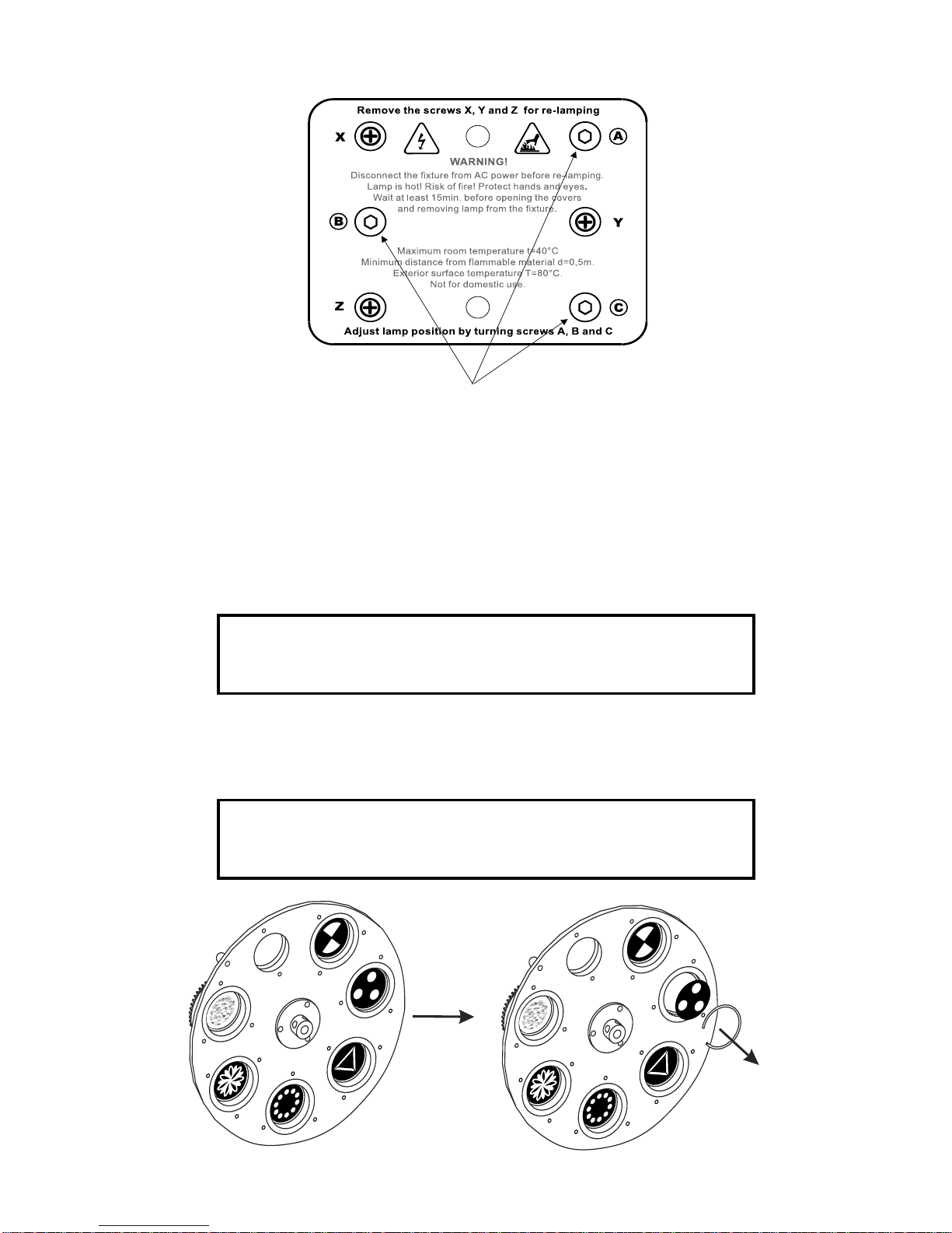
To insert the lamp OSRAM HSR 575/295V/575WGX-9,5orPHILIPSMSR 575/2 95V/575W GX-9,5 ,MSD575
95V/575W GX-9,5 loosen the lamp cover at the rear of head (see the drawings ) by remowing the 3 fastening
screws which are marked "X,Y,Z".Carefully pull out the cover with the lamp socket assembly.If changing the
lamp, remove the old lamp from the socket.Insert the lamp to the socket.
Do not install a lamp with a higher wattage! A lamp like this generates temperatures the device is not de-
signed for.Damages caused by non-observance are not subject to warranty.Please follow the lamp
manufacturer‘s notes!Do not touch the glass-bulb with bare hands during the installation! Make sure that the
lamp is installed tightly into the lampholder system.
Reclose the lamp cover and tighten the 3 screws.
Before striking the lamp, reset the "LAti" counter in the main menu of the Control Board, by pressing the
"Up" and "Down" buttons in one time and then confirming with the Enter-button.
Adjust the lamp position by turning the screw "A,B,C" (see "Lamp adjustment " below).
Donot operatethisfixture withopened housing-cover!
Lamp assembly:
3 phillips screws "X,Y,Z"
Lamp cover
8
4.2 Lamp adjustment:
TheServoSpot 575lampholderisaligned at the factory.Due to differencesbetween lamps,fineadjustment may
improve light performance.
Strike the lamp,open the shutter and the iris,set the dimmer intensity onto 100% and focus the light on a flat
surface (wall).Center a hot-spot(the brightest part of the image) by using the 3 adjustment screws "A,B,C".Turn
onescrewafteranotheraquarter-turnclokwise(counter-clokwise)tosetthe hot-spot inthecenterof the image.If
you cannot detect the hot-spot,adjust the lamp until the light is evenly distributed.
4.3 Inserting/Exchanging rotating gobos
DANGER!
Install the gobos with the device switched off only.
Unplug from mains before!
Ifyouwish to useotherforms and patternsasthestandard-gobos,or if gobos are tobeexchanged,openthetop
cover of the head by loosening 2 screws on the top cover.
Remove the fixation ring with an appropriate tool.Remove the gobo and insert the new gobo. Press the fixation
ring together and insert it in the front of the gobo.
CAUTION!
Never unscrew the screws of the rotating gobo
as the ball bearing will otherwise be opened!
3 adjustment screws "A,B,C"
9
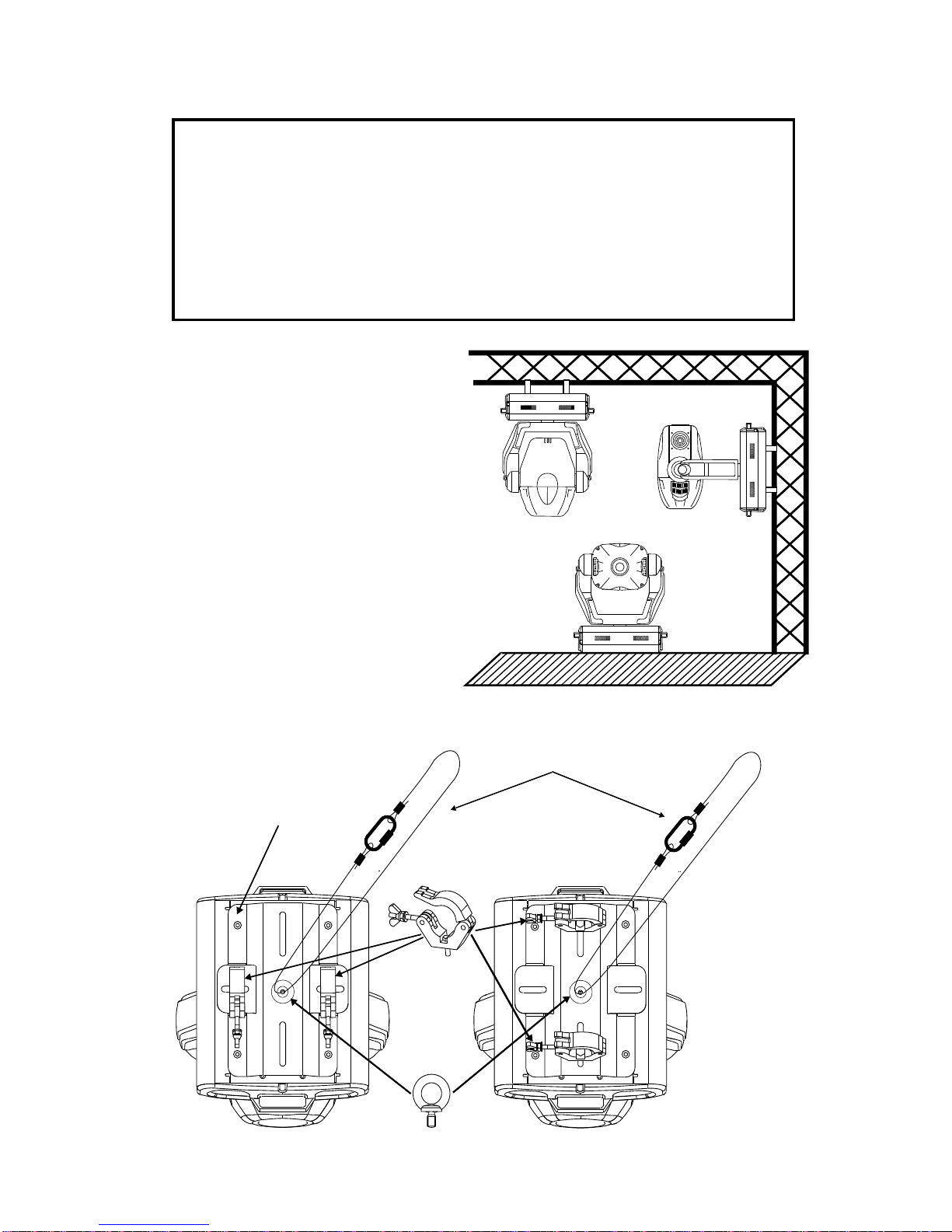
4.4 Rigging the fixture
Dangerof fire!
Wheninstalling thedevice,make surethereis nohighly inflammable
material(decoration articles,etc.)inbetweena distanceof min. 0,5m.
Warning ! Use 2 clamps to rig the fixture on the truss.
Follow the instructions mentioned at the bottom of the base.
Make sure that the device is fixed properly! Ensure that
the structure (truss) to which you are attaching the fixtures is secure.
The ServoSpot 575 can be placed directly on the
stage floor or rigged in any orientation on a truss
without altering its operation characteristics (see the
drawing).
Thefixture’s baseenablestobemountedintwoways.
Use the clamps with screws M12.
Fix a mounting plate and an eye bolt (a part of
delivery)ontheundersideofthebase(see thedrawing
below).
Fasten a safety chain to eye bolt.The safety
chain(cord) must hold at least 10 times the weight of
the fixture. Never use the carrying handles for
secondary attachment.
Secure chain
Clamp
Eye bolt
Mounting plate
10
4.5 Connection to the mains
Connect the fixture to the mains with the enclosed power-plug.
The earth has to be connected!
The occupation of the connection-cables is as follows:
Cable Pin International
Brown Live L
Blue Neutral N
Yellow/Green Earth
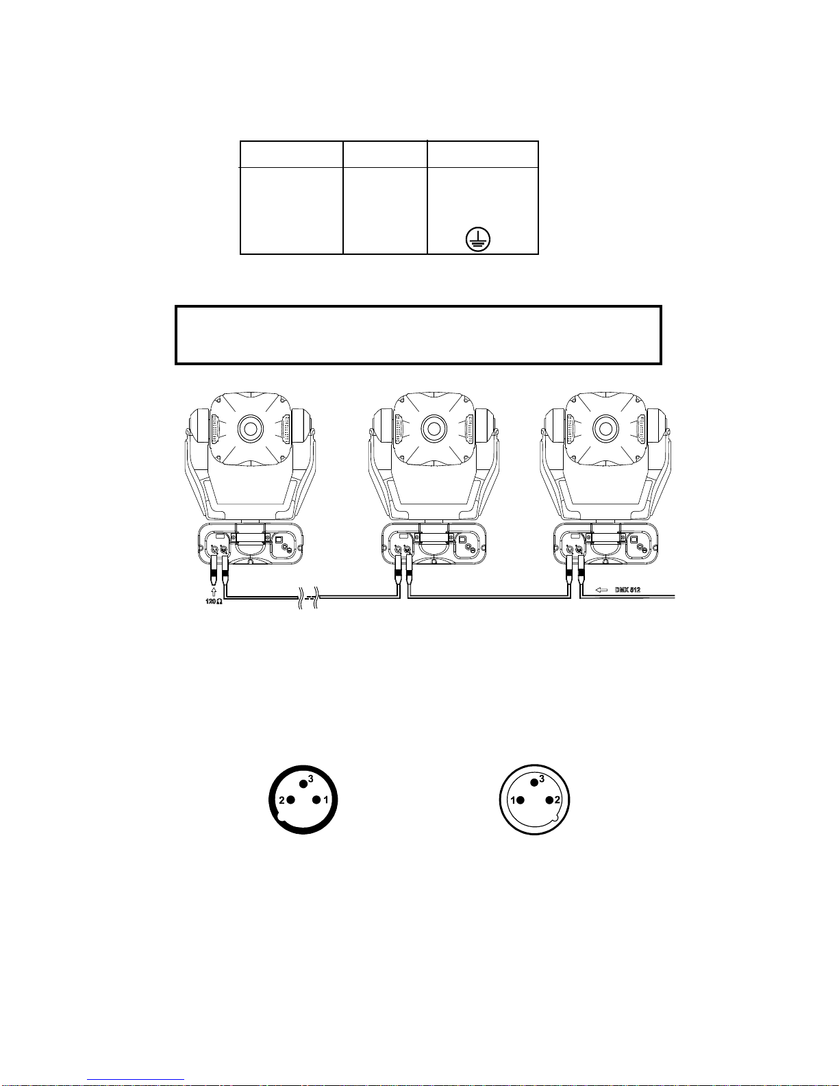
4.6 DMX-512 connection/connection between fixtures
The wires must not come into contact with each other, otherwise
the fixtures will not work at all, or will not work properly.
Only use a stereo shielded cable and 3-pin XLR-plugs and connectors in order to connect the controller with the
fixture or one fixture with another.
Occupation of the XLR-connection:
DMX - output DMX-input
XLR mounting-socket: XLR mounting-plug:
If you are using the standard controllers, you can connect the DMX-output of the controller directly with the
DMX-input of the first fixture in the DMX-chain.If you wish to connect DMX-controllers with other XLR-outputs,
you need to use adapter-cables.
Building a serial DMX-chain:
Connect the DMX-output of the first fixture in the DMX-chain with the DMX-input of the next fixture. Always
connect one output with the input of the next fixture until all fixtures are connected.
Caution: At the last fixture, the DMX-cable has to be terminated with a terminator.Solder a 120 Ohm resistor
between Signal (–) and Signal (+) into a 3-pin XLR-plug and plug it in the DMX-output of the last fixture.
1- Ground
2 - Signal (-)
3 - Signal (+)
1- Ground
2 - Signal (-)
3 - Signal (+)
11
5. DMX PROTOCOL
Channel Channel Value Function Type of control
16 bit 8 bit
11 Pan
0-255 Pan movement by 530° proportional
2 Pan fine
0-255 Fine control of pan movement proportional
3 2 Tilt
0-255 Tilt movement by 280° proportional
4 Tilt fine
0-255 Fine control of tilt movement proportional
5 3 Speed of PAN/TILT movement
0 Max.speed (tracking mode) step
1-249 From max.speed to min.speed (vector mode) proportional
250-252 Max.speed,(track.mode),black-out while color or step
gobo changes
253-255 Max.speed (vector mode),black out while pan/tilt step
moving or color/gobo changes
6 4 Lamp on/off,reset,fans speed control
0-127 From max.speed of fan to min. speed of fan proportional
128-139 Lamp on,reset, step
140-229 No function step
230-239 Lamp off after 3 sec step
240-255 No function step
7 5 Colours 1
0 Open/white proportional
13 Light blue proportional
26 Red proportional
38 Blue proportional
51 Light green proportional
64 Yellow proportional
77 Magenta proportional
90 Cyan proportional
102 Green proportional
115 Orange proportional
128-190 Forwards rainbow effect from fast to slow proportional
191-193 No rotation step
194-255 Backwards rainbow effect from slow to fast proportional
0-255 Colour macro function (channel 8 set from 128- proportional
255)-64 different colours in following order:white,
pink,magenta,red,orange,yellow,green,cyan,blue,UV
8 6 Colours 2
0-11 White step
12-23 Deep red step
24-35 Deep blue step
36-47 Pink step
48-59 Cyan step
60-71 Magenta step
72-83 Yellow step
84-95 5600K correction filter step
96-107 3200K correction filter step
108-119 UV filter step
12
Channel Channel Value Function Type of control
16 bit 8 bit 120-127 White step
128-255 Enable macro color function on channel 7 step
9 7 3-facet prism rotatin control,Prism macros
0 Open position (no prism) step
1- 63 Forwards rotation from fast to slow proportional
64 No rotation step
65-127 Backwards rotation from slow to fast proportional
128-255 Prism/gobo macros
128-135 Macro 1 step
136-143 Macro 2 step
144-151 Macro 3 step
152-159 Macro 4 step
160-167 Macro 5 step
168-175 Macro 6 step
176-183 Macro 7 step
184-191 Macro 8 step
192-199 Macro 9 step
200-207 Macro 10 step
208-215 Macro 11 step
216-223 Macro 12 step
224-231 Macro 13 step
232-239 Macro 14 step
240-247 Macro 15 step
248-255 Macro 16 step
10 8 Static gobos
0-7 Open/hole step
8-15 Gobo 1 step
16-23 Gobo 2 step
24-31 Gobo 3 step
32-39 Gobo 4 step
40-47 Gobo 5 step
48-55 Gobo 6 step
56-63 Gobo 7 step
64-71 Gobo 8 step
72-79 Gobo 9 step
80-223 Shaking gobos with variable speed
80-95 Gobo 1 step
96-111 Gobo 2 step
112-127 Gobo 3 step
128-143 Gobo 4 step
144-159 Gobo 5 step
160-175 Gobo 6 step
176-191 Gobo 7 step
192-207 Gobo 8 step
208-223 Gobo 9 step
224-255 Gobo wheel rotation from slow to fast proportional
11 9 Rotating gobos
0-31 Open/hole step
32-63 Rot.gobo 1 (metal) step
64-95 Rot.gobo 2 (metal) step
96-127 Rot.gobo 3 (metal) step
128-159 Rot.gobo 4 (dichroic) step
160-191 Rot.gobo 5 (dichroic) step
192-223 Rot.gobo 6 (glass) step
224-255 Rot.gobo wheel cont.rotation from slow to fast proportional

13
Channel Channel Value Function Type of control
16 bit 8 bit
12 10 Rotating gobo index,rotating gobo rotation
0-127 Gobo indexing proportional
128-190 Forwards gobo rotation from fast to slow proportional
191-192 No rotation step
193-255 Backwards gobo rotation from slow to fast proportional
13 11 Iris
0 Open step
1-179 Max.diameter to min.diameter proportional
180-191 Closed step
192-223 Pulse closing from slow to fast proportional
224-255 Pulse opening from fast to slow proportional
14 12 Focus,multistep zoom
0-85 Zoom15°-Continuousadjustmentfromfarto near proportional
86-170 Zoom18°-Continuousadjustmentfromfar tonear proportional
171-225 Zoom22°-Continuousadjustment fromfarto near proportional
15 13 Shutter,strobe
0-31 Shutter closed step
32-63 No function (Shutter open) step
64-95 Strobe-effect from slow to fast (max.10 flashes/s) proportional
96-127 No function (Shutter open) step
128-159 Pulse-effect in sequences from slow to fast proportional
160-191 No function (Shutter open) step
192-223 Random strobe-effect from slow to fast proportional
224-255 No function (Shutter open) step
16 14 Dimmer intensity
0-255 Gradual adjustment of the dimmer intensity proportional
from 0 to 100%

14
6. Addressing
The control board on the front panel of the ServoSpot 575 allows you to assign the DMX fixture address, which
is defined as the first channel from which the ServoSpot 575 will respond to the controller.
If you set, for example, the address to channel 5, the ServoSpot 575 will use the channel 5 to 20 for control.
Please, be sure that you don’t have any overlapping channels in order to control each ServoSpot 575 correctly
and independently from any other fixture on the DMX data link.
If two, three or more ServoSpot 575 are addressed similarly, they will work similarly.
For address setting follow this procedure:
1) Switch On the ServoSpot 575 and wait until the fixture reset has finished ("rSt" is flashing at the display).
2) Press the [Mode] key in order to access the main menu.Browse through the menu by pressing the [Up]
and [Down] keys until the display shows "A001".Confirm by pressing [Enter] key and the letter "A" will flash.
3) Use the [Up] and [Down] keys to select the desired address.
4) Confirm by pressing [Enter] or [Mode] to cancel.
Controlling:
After having addressed all ServoSpot 575 , you may now start operating these via your lighting controller.
Note: After switching on, the ServoSpot 575 will automatically detect whether DMX 512 data is received or not.
If there is no data received at the DMX-input, the display will start to flash "A001"withactuallyset address.
This situation can occur if:
- the 3 PIN XLR plug (cable with DMX signal from controller) is not connected with the input of the device
- the controller is switched off or defective, if the cable or connector is defective or the signal wires are
swap in the input connector.
Note: It’s necessary to insert the XLR termination plug (with 120 Ohm) in the last lighting in the link in order to
ensure proper transmission on the DMX data link.
7. Remotely controllable functions
7.1 Lamp
The ServoSpot 575 is run with a PHILIPS MSD 575,MSR 575/2 or OSRAM HSR 575/2 lamp.
Arelayinsideofthe ServoSpot 575allows youtoswitchOnand Off the lamp via itself controlboardonthefront
panel of base or via your controller without affecting the rest of the lighting.
7.2 Switching On and Off the lamp by the control board
1. Switch On the ServoSpot 575 and wait until the fixture reset has finished.
2. Press the [Mode] key in order to access the main menu.Browse through the menuby pressing the [Up] and
[Down] keys until the display shows "LAMP".Confirm by pressing [Enter] key.
3. Use the [Up] and [Down] keys to select "On" for switch On the lamp and "Off" for switch Off the lamp and
press [Enter] to confirm or [Mode] to cancel.
Note: It is also important to note, that the discharge lamp is cold restrike types, that means, that they have to be
cold before re-striking. For this reason, you have to wait 5 minutes (max.speed of fan must be adjusted) after
having switched Off the lamp before you can switch it back On again. If you try to switch On the lamp within 5
minutes after having switched it Off, the ServoSpot 575 will store this information and automatically ignite the
lamp when the 5 minutes period has expired.The message "HEAt" will appear on the control board display of
the ServoSpot 575. If the ignition of the lamp is seven times unsuccessful, on the display will appear "LA.Er",
meaning that the lamp could be damaged or even missed, or there could be a failure on the ignitor or ballast.
7.3 Colour wheels
The ServoSpot 575 contains two colour wheels both with 10 color positions - 9 of these with dichroic colors and
the last one white.The wheel 1 can be positioned between two adjacent colors in any position.It is also possible
to rotate the color wheel 1 continuously at different speeds("Rainbow effect“ in both directions). Hot and cold
colour temperature filters (3200K and 5600K) and UV filtr are situated on the colour wheel 2.
By color macro function it is possible to obtain 64 different colours in following order:white, pink, magenta, red,
orange, yellow, green, cyan, blue, UV
7.4 Static gobo wheel
Thewheelhas9 metal gobosplusanopen position.Adjustablegobowheelrotation from slowtofast,gobo-shake
function.

15
7.5 Rotating gobo wheel
The rotating gobo wheel includes 3 metal gobos, 1 glass gobo and 2 dichroic gobos rotating in both directions,
indexable, rotating gobo wheel continuousli rotation from slow to fast.The rotating gobos can be interchanged.
7.6 3-facet rotating prism
The 3-facet prism rotating in both directions at different speeds,16 prism-gobo macros
7.7 Iris
Motorized adjustable iris,variable pulse effects.
7.8 Focus-multistep zoom
Motorizedfocusenablesthe beamtobe focusedanywhereonstageat differentbeamangles:15°,18°,22°,provided
by the special multistep zoom.
7.9 Dimmer/Shutter/Strobe
Smooth 0 - 100 % dimming is provided by the combined mechanical dimmer/shutter unit.This unit may also be
used for strobe effect (1 - 10 flashes per second)
7.10 Fan
The ServoSpot 575 is cooled by three axial fans - two in the projector head and one in the base.The speed of
the fan (and of course the noise) can be continuously reduced if very quiet performance is required.
By the Control Board using the "FAnS" function you can choose 5 types of low fan speed operating:
1. "HIGH" - high (max.) speed of fans
The cooling fans work on max. speed (max.cooling)
2. "rEG" - continuous controlling of the fan speed
the fan automatically raises its speed in order to control inside temperature of the lighting, if the
temperatureinsideincreases aboutcertainlevel(thelowfanspeedreduces the coolingofthelighting).
This cycle can repeat several times until the temperature inside is on suitable level.
3. "LoOF" - low speed/Switch Off the lamp operating
the fan keeps the adjusted low speed until the temperature exceeds max. inside temp. Then the
ServoSpot 575 automatically switch Off the lamp.
4. "LoHI" - low/high speed of the fan operating
the fan keeps the adjusted low speed until the temperature exceeds max. inside temp. of the fixture,
then the ServoSpot 575 automatically switch from low to high the fan speed.
5."Auto" - continuous controlling of the fan speed without the DMX value.
This mode is similar to "reG", but the initial level of the fan speed can´t be adjusted by the DMX.
8. Control Board
Thecontrolboardsituated on thefrontpanelofthe ServoSpot 575 offersseveralfeatures.Youcansimplyset the
lighting address, read the number of lamp or unit hours, switch On and Off the lamp, run test show, make a reset
and also use special functions for manual, demo and service purposes.
8.1 Main functions
The main menu is accessed by pressing the [Mode] key - press this one so many times until the display shows
message "A001" (with actually stored address). Browse through the menu by the pressing [Up] and [Down]
keys - the display shows step by step these messages:A001, rPAn, rTilt, 16br, Lati, Poti, LAMP, dEMo, rESE,
SPEC.Press [Enter] if you wish to select one of them.The functions are described in the following sections and
the function hierarchy is shown below.

16
DMX 512 Address settings
Theletter"A" flashes.Usethe [Up]and [down]keys to selectrequiredaddress (001 -497)and press [Enter] to
confirm or [Mode] to cancel and return to the main menu.
Pan reverse
This function allows you to invert the pan movement.Use the [Up] and [Down] keys to select "On" if you wish
this feature or "Off" if you don’t wish this feature and press [Enter] to confirm or [Mode] to cancel and return to
the main menu.
Tilt reverse
Thisfunctionallowsyouto invertthetiltmovement.Use the [Up] and[Down] keys toselect "On" if youwishthis
feature or "Off" if you don’t wish this feature and press [Enter] to confirm or [Mode] to cancel and return to the
main menu.
Movement resolution
By this function you can adjust the desired movement resolution 8 or 16 bit. Use the [Up] and [Down] keys to
select "On" if you wish the 16 bit high resolution or "Off" if you wish only 8 bit resolution and press [Enter] to
confirm or [Mode] to cancel and return to the main menu.
Note: If youadjust the 16bitresolution, the fixturewilloccupy 16DMXchannels, ifyouadjustthe 8bitresolution,
the fixture will be operated by only 14 DMX channels.Please, check the DMX protocol.
Lamp On time
This option enables you to read the total number of hours that the lamp has been powered On.Press [Enter] or
[Mode] to return to the main menu.In order to reset the counter to 0, you have to hold the [Up] and [Down]-
button and press the [Enter]-button.
Power On time
By this option you can read the total number of hours that the ServoSpot 575 has been powered On. Press
[Enter] or [Mode] to return to the main menu.
Switch On/Off the lamp
Use the [Up] and [Down] keys to select "On" if you wish the switch On the lamp or "Off" if you wish switch Off
the lamp and press [Enter] to confirm or [Mode] to cancel and return to the main menu.

17
Demo sequences
Thisfunctionallowsyoutorunaspecialdemo-test sequences without anexternalcontroller,whichwillshowyou
some possibilities of using ServoSpot 575. Press [Up] and [Down] keys to select the "Mod1" or "Mod2"
sequences.The "Mod1" is suitable for projections on the wall, ceiling or ground without any head-movement,
the "Mod2" uses all ServoSpot 575 functions and therefore is good for a complete introduction of the fixture.
Reset Function
Press [Enter] key to run reset.This option enables the ServoSpot 575 to index all effects (functions) and return
to their standard positions.
8.2 SPEC - Special functions
Use the [Up] and [Down] keys to browse through the special functions and select the one by pressing [Enter].

18
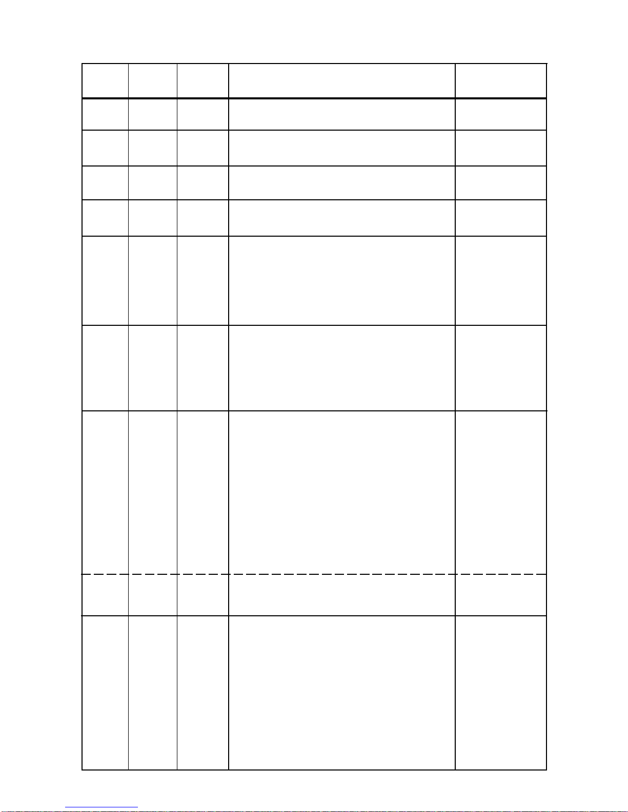
Manual control of effects
This function allows you to control manually the channel functions of the fixture. Use the [Up] and [Down] keys
to select desired function and press [Enter] to adjust the effect or [Mode] to cancel and return to the menu.
Lamp On automatically
This menu allows you to turn the lamp On after switching the fixture On and switch On/Off the lamp light sensor.
Lamp On after switching the fixture On
This function enables to turn the lamp On automatically after switching the fixture On.Use the
[Up] and [Down] keys to select "On" if you wish to turn the lamp On automatically after switching
the fixture On or "Off" if you wish the lamp Off after switching On the fixture and press [Enter] to
confirm or [Mode] to cancel and return to the menu.
Switch On/Off the lamp light sensor
Use the [Up] and [Down] keys to select "On" if you wish to switch the lamp light sensor On and
press [Enter] to confirm or [Mode] to cancel and return to the menu.The option"On" is for the
standard operation.
Use the [Up] and [Down] keys to select "Off" if you wish to switch the lamp light sensor Off and
press [Enter] to confirm or [Mode] to cancel and return to the menu.
Important:The option"Off" is for "emergency operation" only if the lamp light sensor is defective and
you will wait for a delivery of the spare light sensor! If the lamp light sensor was switched Off,the error
messages "LAEr,SnEr,HEAt" will not appear on the display (only the message "HEAt" will appear if the lamp
was turned Off and On within 5 minutes ) and at switching On of the lamp the electronics will still try to ignite the
lampuntilitshines(evenwhenthelampis damaged or absent), onthisaccountsomeelectronics partscouldbe
damaged!
19
DMX values
Readout DMX values of each channel received by the fixture.Use the [Up] and [Down] keys to select desired
channel and press [Enter] to read its value coming to the fixture or [Mode] to cancel and return to the menu.
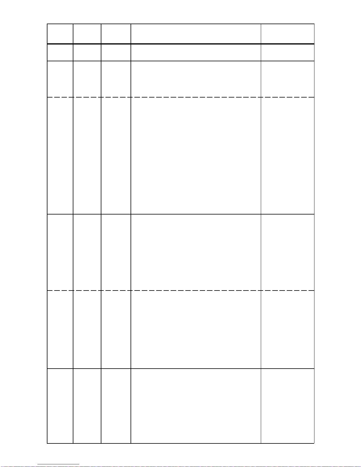
Display adjusting
This function allows you to adjust the display settings:
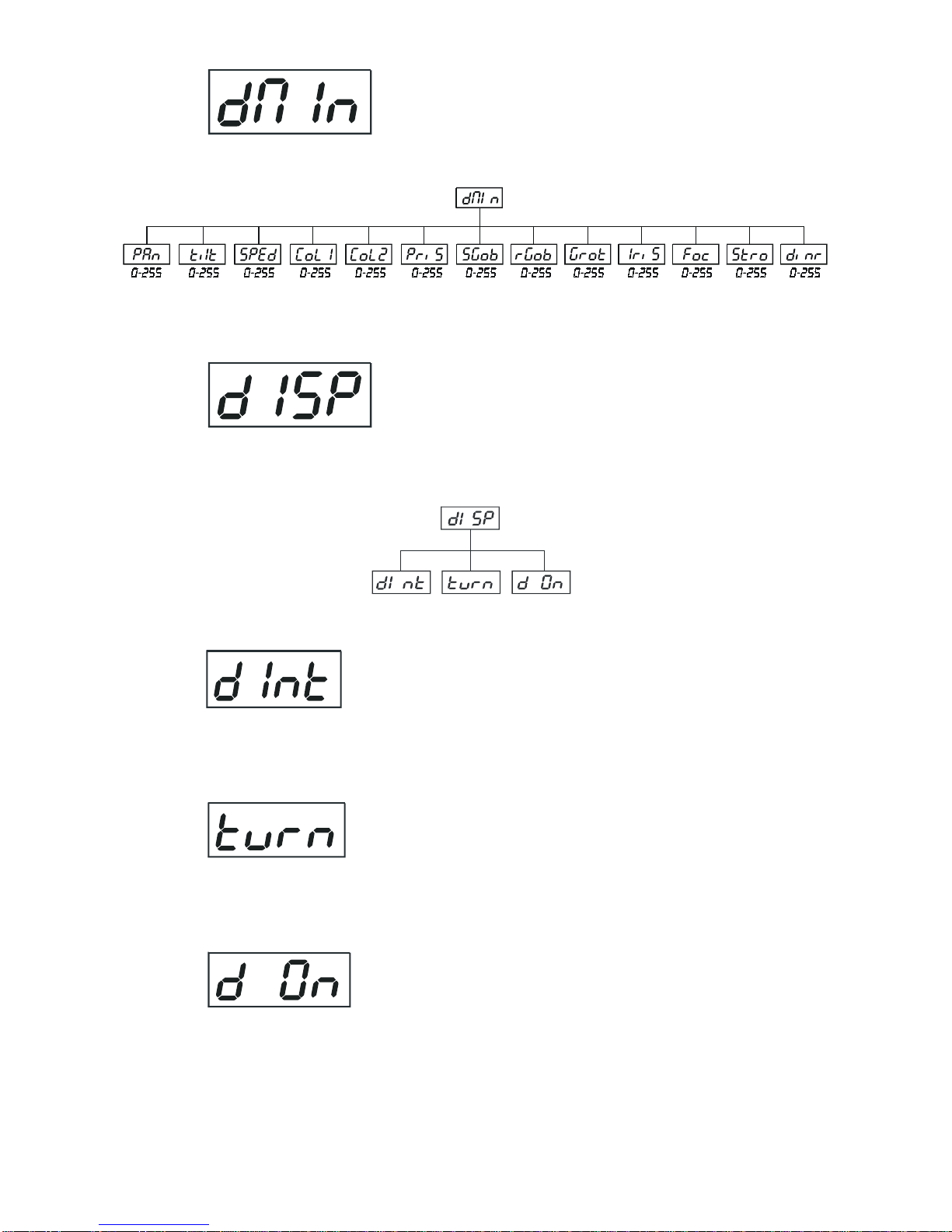
Display intensity
By this function you can adjust from 20% to 100% the display intensity . Use the [Up] and [Down]
keystoselectthelevelofthedisplayintensity and press [Enter] toconfirm or [Mode] tocanceland
return to the menu.
Display-reverse
With this function, you can rotate the display by 180°. Use the [Up] and [Down] keys to select
"normal display" or "display turned by 180°" and press [Enter] to confirm or [Mode] to cancel
and return to the menu.
Display- On
This function allows you to keep the display On or to turn Off automatically 2 minutes after last
pressing any key on the control board.Use the [Up] and [Down] keys to select "On" if you wish to
keep the display On or "Off" if you wish to turn Off automatically 2 minutes after last pressing any
key on the control board and press [Enter] to confirm or [Mode] to cancel and return to the menu.

20
PAN/TILT feedback
This function allows to return the mowing head to the required position after changing the position by external
force (e.g.by stroke).Use the [Up] and [Down] keys to select "On" if you wish to anable this function or "Off"
if you wish not to return the mowing head to the required position and press [Enter] to confirm or [Mode] to
cancel and return to the menu.
Note: If the feedback was switched Off , the pan/tilt position is changed by external force and the feedbeck is
switchedOnagain,themoving headmightnottobe synchronizedwiththeDMX signal.You havetomakeareset
in order to synchronize the moving head with the DMX signal.
Lamp Off via DMX
This function allows you to switch Off the lamp by DMX. Use the [Up] and [Down] keys to select "On" if you
want to switch Off the lamp by DMX or "Off" if you don’t want to switch Off the lamp by DMX and press [Enter]
to confirm or [Mode] to cancel and return to the menu.
Temperature
Temperature readoutsofthefixtureinsidein Celsius.Insidetemperaturesbelow80°Carenotcritical.80° C and
more lead to the lamp being switched off.Please note that the outside temperature should not exceed 40° C.
Low fan speed operating
By using this function you can choose 5 types of low fan speed operating. Browse through this menu by the
pressing [Up] and [Down] keys - the display shows step by step these messages: "Auto,HIGH, reG, LoOF,
LoHI". Press [Enter] if you wish to select one of them or [Mode] to cancel and return to the menu.
high (max.) speed of fans
The cooling fans work on max.speed (max.cooling)
continuous controlling of the fan speed
the fan automatically raises its speed in order to control inside temperature of the lighting, if the
temperature inside increases about certain level (the low fan speed reduces the cooling of the
lighting).This cycle can repeat several times until the temperature inside is on suitable level.
Table of contents


