Setec Power DC Quick EV Charger User manual

20kw DC Quick EV Charger
OCPP 1.6
Installation Manual

Table of Contents
INTRODUCTION
.............................................................................................
3
Features ...................................................................................................................................................
3
Applications
..............................................................................................................................................
3
IMPORTANT SAFETY
AND
GROUNDING INSTRUCTIONS
....................................
4
Safety
and
Compliance
............................................................................................................................
4
Grounding
Instructions
.............................................................................................................................
4
B
EFORE
I
NSTALLATION
..................................................................................
5
Safety
Requirements
................................................................................................................................
5
Recommended
Tools
...............................................................................................................................
5
Important
Safety
Instructions
..................................................................................................................
5
GENERAL SPECIFICATIONS
............................................................................
6
PRODUCT PRESENTATION
.............................................................................
7
INSTRUCTION
................................................................................................
8
Location
.....................................................................................................................................................
8
Installation Procedure
..............................................................................................................................
8
DC CONNECTORS
........................................................................................
10
CABLE CONNECTIONS
......................................................................................................................
11
4G CARD INSERT
...............................................................................................................................
11
CHARGING SIMPLE PROCESS
......................................................................
12
OPERATION
.........................................................................................................................................
12
CHARGING PROCESS DETAILS
.....................................................................
13

INTRODUCTION
The DC Quick EV
Charger
is
the
top
choice
to
power
battery
electric vehicles (BEV)
today.
It
is
designed for
quick
charging
in
retail
and commercial
parking
spaces,
fleet charging stations,
highway rest areas,
etc.
The DC Quick EV
Charger
has network 4G, WIFI, Ethernet
communication
capability
and is
able
to controlled by mobile phone to check charger’s information through your OCPP
server
,
such
as
the
location of
charging
stations,
charging
progress
and
billing
information.
DC
Quick
EV
Charger has a clear
and
straight forward user interface and safety system of
power
supply to
provide
the
best choice for
drivers charging their cars
.
It
can
also
integrate
with
renewable
energy,
such
as
solar
power
to provide
the
most
energy
saving
infrastructure
for
EV
system
development.
Features
1)
Provides a high-contrast, 10 inch touch LCD screen interface to easy operation
and view status.
1) Offers customers the convenience of full start and stop charging control from an
authorized RFID smart card.
2) Obvious signal light shows charging status.
3) Emergency button to stop immediately.
4) Multi-connectors are suitable for all the EV cars.
5) Charge modules be inserted easily.
Applications
Public and
private
parking
areas
Community parking
areas
Parking areas
of
hotels,
supermarkets
and
shopping
malls
Charging
stations
Highway
rest
areas

IMPORTANT SAFETY
AND
GROUNDING
I
NSTRUCTIONS
Safety and Compliance
1.Read
the
manual
before
installation or usage of
device.
2.Do not
put
tools, material or body
parts
into
the
electric
vehicle
connector.
3.Do not use
the
DC
Quick
EV
Charger
if
the
chassis,
power cord
or
charging
cable
are
frayed,
have
broken insulation, or
any
other
signs
of
damaged.
4.
Do not install or use
the
DC Quick EV Charger if the
enclosure
is
broken,
cracked,
open
or
has
any
other
indications
of
damage.
5.
The DC Quick EV
Charger
should
be
installed
only
by
a
qualified
technician.
6.
Make sure
that
the
materials used
and
the installation procedures
follow
local building
codes and
safety
standards.
7.
The information provided in this manual in no way exempts
the
user
of responsibility to
follow all applicable codes or
safety
standards.
8.
The manufacturer is
not
responsible for
physical
injury,
damage to property
or
equipment
caused
by the installation of this
device.
9.
This document
provides
instructions
for
the
DC
Quick EV Charger
and should
not
be used
for
any
other
product. Before installation or
use
of
this
product,
you should
review
this
manual carefully and consult
with
a
licensed
contractor,
licensed electrician,
or
trained
installation expert
to
make sure of compliance
with
local
building
codes
and
safety
standards.
Grounding
Instructions
An
equipment
grounding
conductor or a
grounded,
metal,
and
permanent
wiring
system
is
required
for
the
DC
Quick
Charger
connection.
This
should
be
run with circuit conductors
and
connected
to the equipment
grounding
bar or lead on the
DC
Quick
Charger.
Notes:
Do not install charging station in locations where it may be exposed to direct
sunlight and inclement weather. Recommend waterproof shed for EV
charger.
If the charging station is to be stored, keep it in its original packaging in an
appropriate place:
· On dry base ground
· Sheltered from dust, inclement weather, and sunlight;
· storage temperature: -30°C to 70°C
· Humidity: 5–95%

B
EFORE
I
NSTALLATION
Safety
Requirements
Be sure to preview
the
standard
operating
procedures
(SOP)
and
ensure
local
building
and
electrical codes are
reviewed
before installing the DC Quick
Charger.
The DC Quick
Charger
should
be
installed by
a
trained
technician
according to the
instruction manual
and
local safety regulations.
Use appropriate
protection when
connecting
to
the
main
power
distribution
cable.
Recommended
Tools
The following tools are recommended for
the
DC Quick Charger installation:
(1x)
No.2
Philips
screw
driver
M12
expansion bolts
(1x)
Concrete drill
(1x)
Wire
cutters
(1x)
Torx®
Tamper-Resistant
TH30
screwdriver
(1x)
16mm
ratcheting
wrench
for
the
base
(3x)
Ring
terminal
(TERM,
SOLIS
R
50mm²,
M8)
for
models with
380V,
or
400V input
(1x)
Ring
terminal
(TERM,
SOLIS R 35mm²,
M10)
for
ground
wire
Important Safety Instructions
Save these
Instructions
The DC Quick
Charger
should be installed only by
a
licensed
contractor,
and/or a licensed
electrician
in
accordance with all applicable state, local and
national
electrical
codes and
standards.
Before installing the DC Quick
Charger,
review
this
manual carefully and consult
with
a
licensed
contractor,
licensed electrician and
trained
installation expert to ensure
compliance
with local
building
practices, climate
conditions,
safety standards,
and
state and local codes.
WARNING!
Danger of electrical shock or injury.
Turn
OFF
power
by emergency button
before
working
inside the
equipment
or
removing
any
component.
Do not
remove
circuit
protective
devices
or
any other
component
until
the
power
is turned
OFF.
CAUTION!
TO
AVOID
DAMAGE
TO
THE
CHARGER
OR
PERSONAL
INJURY,
MAKE SURE
THE
INSTALLATION
LOCATION
IS
ABLE
TO SUPPORT
THE
WEIGHT
OF THE DC
QUICK
CHARGER.

6
GENERAL SPECIFICATION
Item
Specifications
Remark
Rated voltage
3 phase 380VAC/single phase220VAC
Voltage fluctuation range
380V /220V
+/-
10%
Number of phases
Three-phase and four-line +PE
Rated frequency
50 or 60 Hz
AC Input
Frequency fluctuation range
+/- 5%
Input power factor
0.99
In rated operation
Input power
20kw +10%
Grounding detection
30mA
Harmonic current
Total 5% or less
Rated Output Capacity
20kw
DC Output
Voltage variable range
50 to 500VDC
Output current
40ADC
Current variable range
0 to 40A
Efficiency
96% or more
Ripple current
6.0Ap-p or less
Degree of Protection IP
IP54
Better use waterproof shed
Ambient temperature
-20 ℃~ 55℃
Structure
Storage temperature
-30℃~ 70 ℃
Chassis dimensions LxWxH
715*500*274mm
Package Weight
100KG( by air)
Include 2 plugs and cables and modules
Certification
CE/IEC 61851
Safety
Emergency stop button
Vehicle connector
CHAdeMO+CCS
OTHERS
Battery communication protocol
CAN / PLC
Management system
OCPP 1.6
Network communication
WIFI, Ethernet
4G (optional)
Cooling method
Force air cooling

7
PRODUCT PRESENTATION
Item
Description
Wire hole
Charging cable from this wire hole
Air hole
Forced air cooling through fans and air hole
Work indicator light
AC power ON-GREEN
DC OUTPUT ON-GREEN
Fault- Red
10’’ touch screen
LCD Touch screen:
Operating states such as remaining charging time and failure information, if a
failure occurred, can be displayed.Setting parameter, view charging status,
etc.
RFID card reader
Tap RFID card here to start and stop charging
Emergency stop button
Emergency Stop Button:
Use this emergency circuit-breaker in order to stop the quick charger in case of
emergency
8
INSTALLATION
Location
①For the best operating conditions and longest life, take care in selecting
an installation site.
Operating life and performance will be influenced by charger location.
②Select a dry and well-ventilated location.
③Do not install charging station in locations where it may be exposed to
direct sunlight and inclement weather. Recommend to install waterproof
shed.
④The front of the charger must remain unobstructed for serviceability.
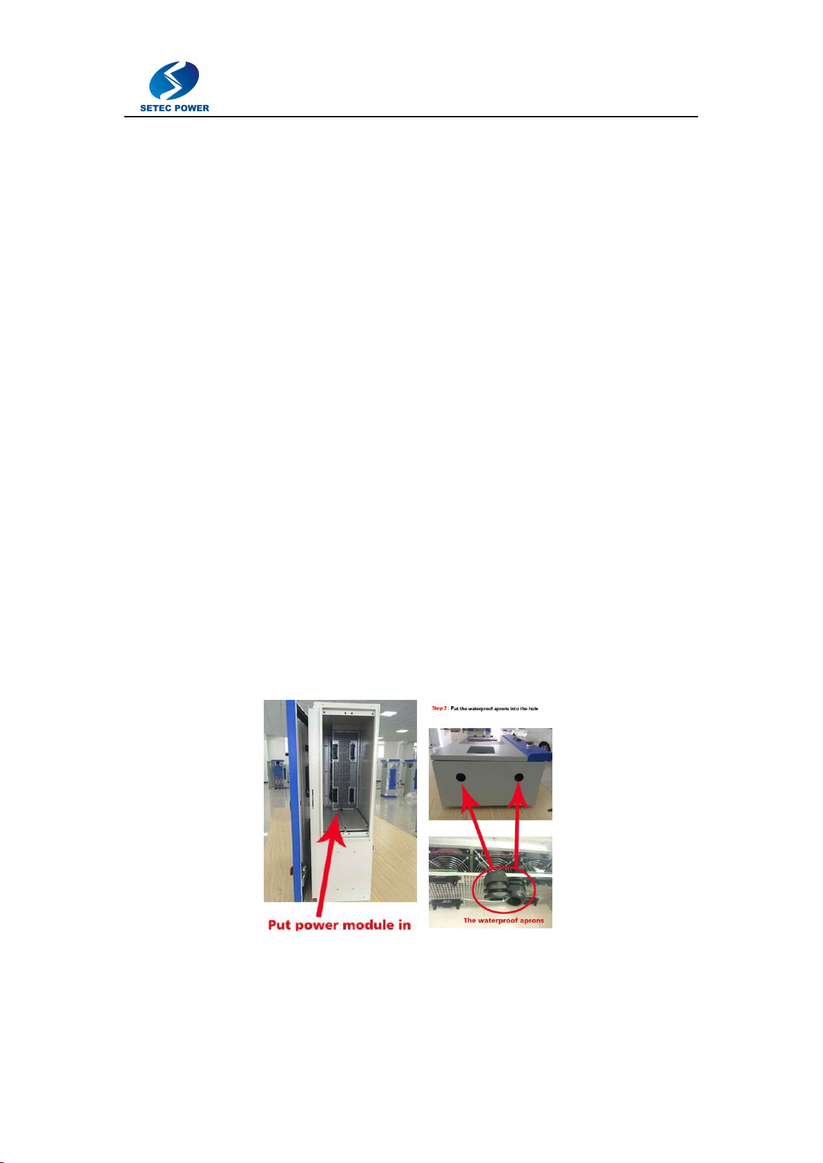
Installation Procedure
The 20KW wall mount charger can be fixed on the wall.
①Insert two power Modules into the shell
②Fixed one part on the wall, other part on the charger.

9
③Wiring Instructions.
AC input:
Noted: 3 phase (380V) AC input cable diameter: 10mm2;
1 Phase (220V) AC input cable diameter: 25mm2
Number
Terminal Assignment
A
Phase 1 (item L1)
B
Phase 2 (item L2)
C
Phase 3 (item L3)
N
Neutral
PE
Ground

10
DC output connector:
1. Chademo
Pin
No.
Line
number
CHAdeMO
definition
function description
1
1
IM
Grounding wire
2
2
CP
Charger sequence signal 1
3
NC
NC
4
6
CP2
Vehicle charge permission
5
Blue
DC-
DC output -cathode
6
Brown
DC+
DC output -anode
7
7
CS
Connector proximity detection
8
8
COM1
CAN-H
9
9
COM2
CAN-L
10
3
CP3
Charger sequence signal 2
4
EL-
Electromagnet&LED - cathode
5
EL+
Electromagnet&LED - anode
Line number 4 and line number 1 should be connected together,it means EL- connect IM
Line number 5 and line number 2 should be connected together,it means EL+ connect CP
11
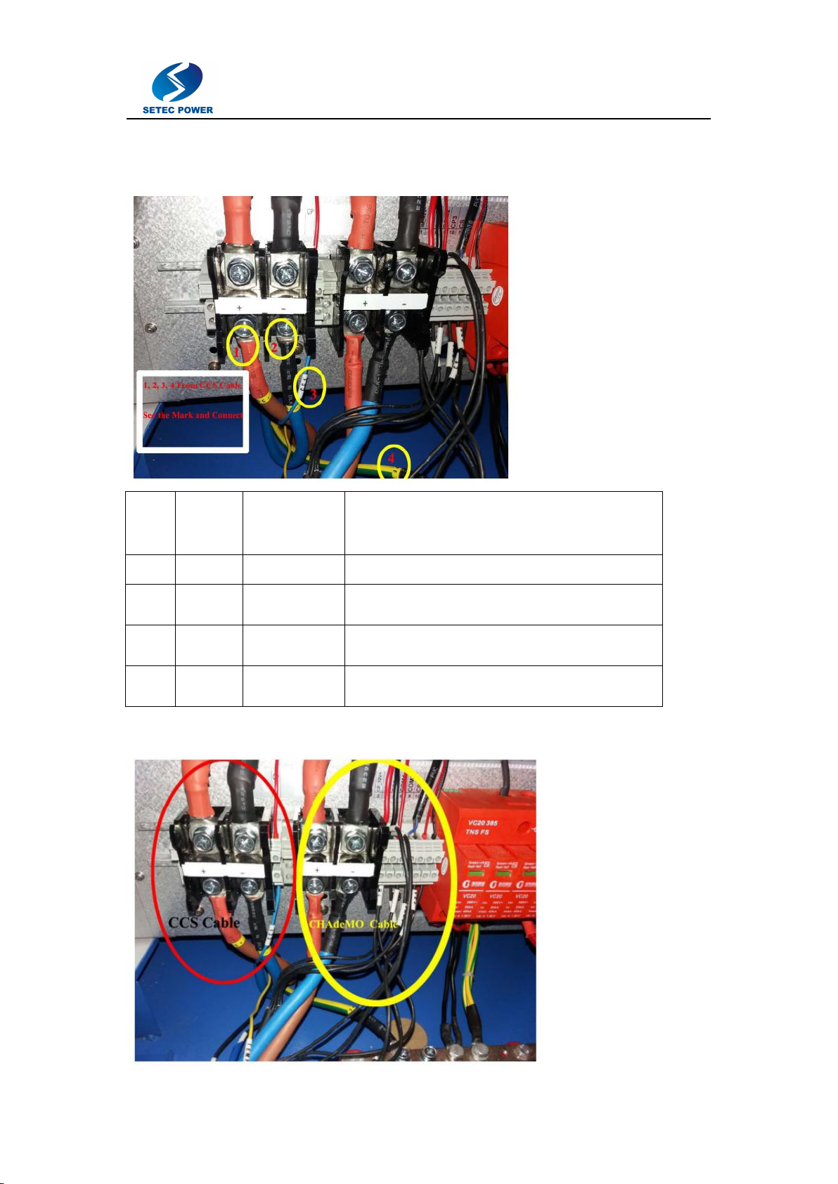
2. CCS connector ( 4 wires)
Pin
No.
Line
number
CCS
definition
Function description
1
1
DC+
DC output -Positive
2
2
DC-
DC output -Negative
3
3
CC1
Signal
4
4
PE
Ground
3. Chademo and CCS
12
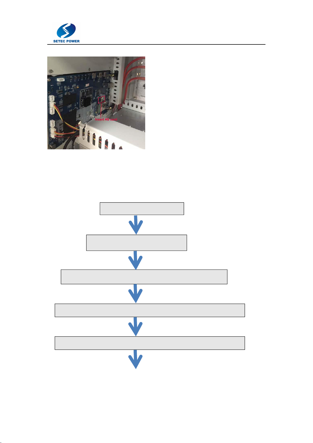
Open the door, 4G card place is in the back of screen.
Charging Simple Process
Make sure DC quick EV charger has been installed and connection wires
correctly according to this manual before operation.
Switch on the Mains MCB
Switch on the Module MCB
Connect the charging connector to the vehicle’s charging port
Select the charging connector according to your vehicle’s charging standard
Tap RFID card on card reader place for seconds till there is a beep sound
13
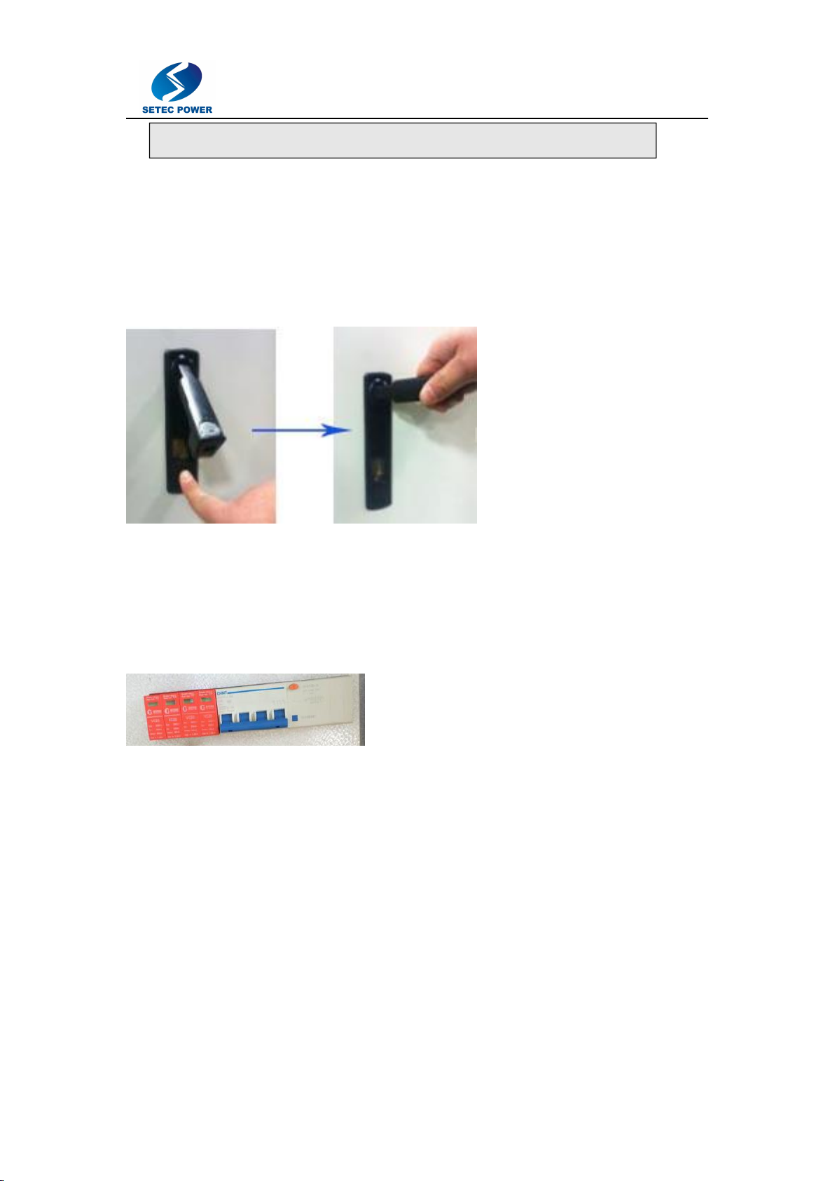
Operation
①Front door open
-Press button under handle and turn handle clockwise in the following order,
then Front door will open.
②Switch ON main
circuit breaker
-Check
whether the status LED for AC power is ON.
-Check module status.
-Check
screen
for card
authentication.
③Closing door
If the above process is completed, make sure to close door
before charging for
safety.
Charging Process Details
Select the charging connector
The screen interface shows EV charger is idle status,insert the charging
connector to vehicle’s charging port accordingly and fixedly. Select the
After beep sound, vehicle start to charge with starting sound

14
connector on the screen interface accordingly.Tap the RFID card at card read
place for several second till there is a beep.Then vehicle starts charging with
sound.You can check charging battery’s power status with OCPP 1.6 system.
Stop charging
When the charging is not finish,and you want to stop charging, please tap RFID card at
card reader place to stop charging.
15
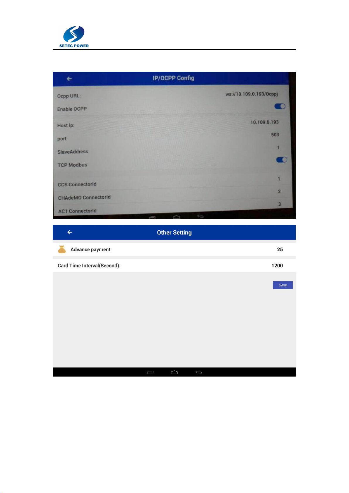
Setting
Setting includes: charging point setting, passwords,network (WIFI,4G) and languages and
etc.
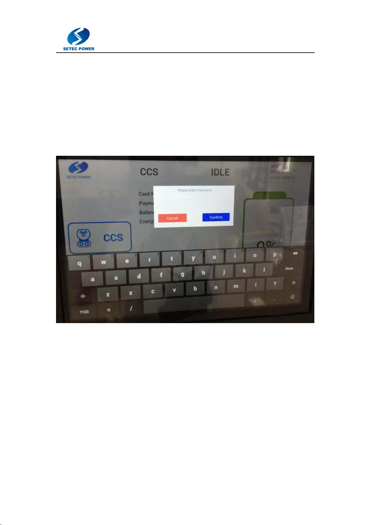
Enter setting interface
Firstly, please click SETEC logo, and enter password interface, type password
(88888888 in default) to enter into setting interface.
16
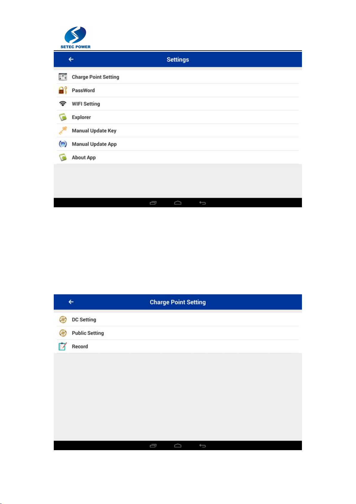
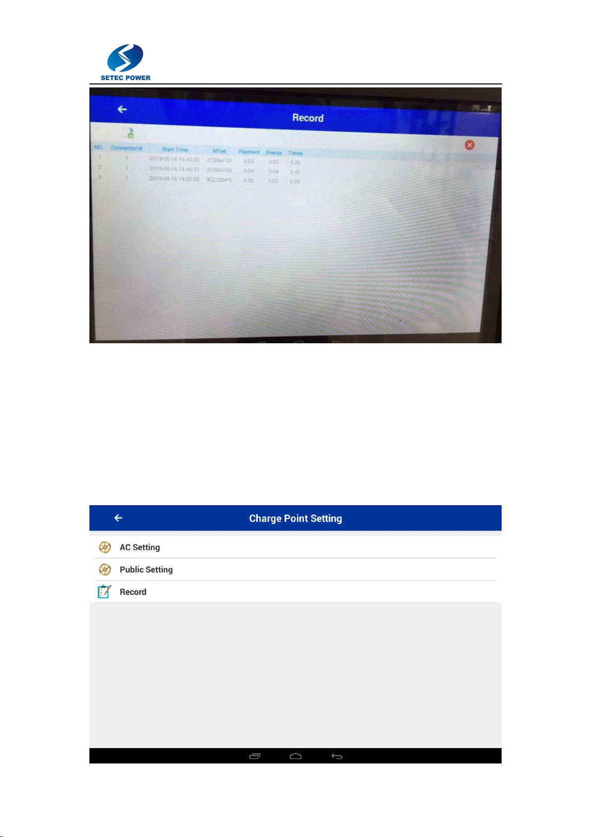
Charging point setting:
17
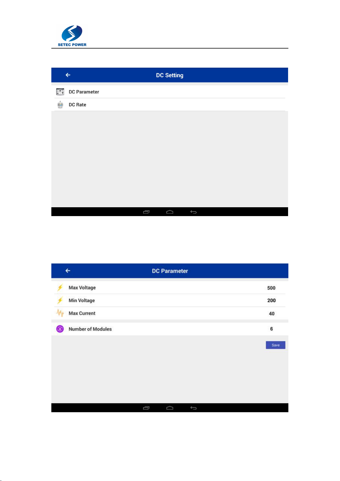
DC setting:
You can set max voltage 500V, min voltage 200V, max current 40A, number of
modules: 6 and click ‘’Save’’. And click ←back to DC setting interface.
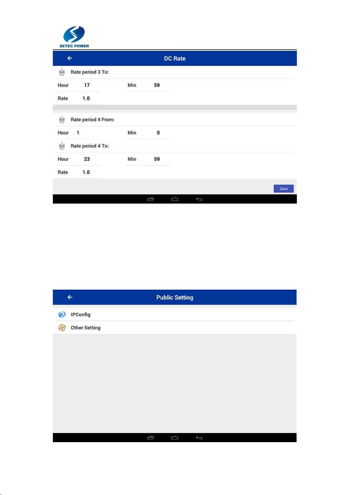
DC Rate setting:
18
Public setting:
19
If you want to use OCPP server, make sure setting your OCPP server URL here and select OCPP
valid.
History Record:
20
AC setting:
Table of contents


