Setec SKM-03.2 Parts list manual

SeTec-SKM03.2-Kunde 02TB21-F
Page 1 of 23
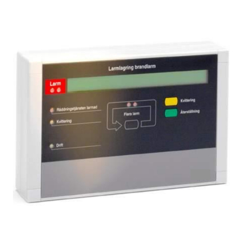
Line-Type Sensor Cable Alarm
SKM-03.2
DIN EN54-22:2015+A1:2020
Technical Description
Item no. BK83000
VdS G221005
Securitas Electronic Security Deutschland GmbH
SeTec Sicherheitstechnik
Hauptstr. 40a
82229 Seefeld
Issue date: 25.02.2021

Technical Description SKM03.2
SeTec-SKM03.2-Kunde 02TB21-F
Page 2 of 23
Table of Contents
1
General / product features.................................................................................4
2
System description .............................................................................................5
2.1
Overview ......................................................................................................................................5
2.2
Technical data...............................................................................................................................6
2.3
Application.................................................................................................................................... 7
2.4
Static operating principle................................................................................................................7
3
Description of components.................................................................................8
3.1
Control unit description ..................................................................................................................8
3.1.1
Connection / terminal assignment .................................................................... 9
3.1.2
Display elements ...........................................................................................10
3.1.3
Signal contacts..............................................................................................11
3.1.4
Operating elements .......................................................................................11
3.1.5
Self-hold alarm with reset function..................................................................12
3.2
Sensor cable description............................................................................................................... 14
3.2.1
Sensor element labelling ................................................................................15
3.2.2
Packaging / cable reel labelling.......................................................................15
3.3
Termination unit description ......................................................................................................... 16
3.3.1 Connection / terminal assignment .....................................................................17
3.4
Description of the optional connector unit...................................................................................... 18
3.4.1 Connection / terminal assignment .....................................................................19
4
Project planning ...............................................................................................20
4.1
Area monitoring .......................................................................................................................... 20
4.2
Installation example .................................................................................................................... 21
4.2.1
Room size from 30m² flat roof up to 20° pitch .................................................21
4.2.2
Room size from 30m² flat roof over 20° pitch ..................................................21
4.3
Sensor cable installation............................................................................................................... 22
5
Tips and tricks ..................................................................................................23

Technical Description SKM03.2
SeTec-SKM03.2-Kunde 02TB21-F
Page 3 of 23
List of Tables
Table 1 Technical data SKM-03.2 .....................................................................................6
Table 2 Terminal assignment SKM-03.2 control unit ........................................................ 10
Table 3 Error messages ................................................................................................ 11
Table 4 Signal contacts SKM-03.2 control unit................................................................. 11
Table 5 Coding switch configuration S1 ..........................................................................12
Table 6 Terminal assignment SKM-03.2 termination unit.................................................. 17
Table 7 Terminal assignment SKM-03.2 connector unit .................................................... 19
Table of Figures
Figure 1 Block diagram SKM-03.2 system .........................................................................5
Figure 2 Connection SKM-03.2 control unit .......................................................................9
Figure 3 Front panel SKM-03.2 control unit..................................................................... 10
Figure 4 SKM-03.2 termination unit with decal "F"........................................................... 16
Figure 5 Connection SKM-03.2 termination unit............................................................... 17
Figure 6 SKM-03.2 connector unit with decal "F" ............................................................. 18
Figure 7 Connection SKM-03.2 connector unit................................................................. 19

Technical Description SKM03.2
SeTec-SKM03.2-Kunde 02TB21-F
Page 4 of 23
1
General / product features
the SKM-03.2 sensor cable alarm is a line-type heat detector
maximum sensor cable length 300 m
temperature increases are detected reliably
sensor cable resistant to mechanical and chemical influences, corrosion, moisture and
dust
easy and very cost-effective system installation
easy start-up without special tools
basic settings can be configured on site using a DIP switch
alarm indicator meets DIN 14 623 "Parallel display for fire alarms"
DIN / EN 54-22:2015, A1I, A2I and CI approved
VdS testing as per DIN / EN 52-22 pending
The sensor cable monitoring system enables early detection of a fire as well as
overheating of e.g. conveyor belts, cable lines or transportation tunnels. It can be installed
on the ceiling or directly above objects for the purpose of detection.
The sensor cable requires very little space and also detects in rough ambient conditions
other fire alarm systems will produce false alarms. The system consists of the sensor cable
(3-core) of the SKM control unit and the termination box. The minimum triggering level for
the temperature can be selected according to classes A1I, A2I and CI.

Technical Description SKM03.2
SeTec-SKM03.2-Kunde 02TB21-F
Page 5 of 23
2
System description
2.1
Overview
Figure 1 Block diagram SKM-03.2 system
The SKM-03.2 is a resettable line-type heat detector.
The system consists of the components
control unit with termination unit BK83000
sensor cable, red BK83001
optional connector units BK83004
Cables up to 300m can be connected as the sensor cable. The sensor cable is typically
installed under the ceiling when monitoring areas.
The cable being exposed to heat in the case of a fire changes the electrical properties of
the cable, which is detected by the control unit and triggers the alarm.
LEDs on the control unit indicate the modes operation, fault and alarm. In addition, dry
contacts can output fault and alarm to external signalling units.
The alarm can be configured for response grade A and C according to EN 54-22 via coding
switches.
The system further offers the option to self-hold an alarm even after the trigger for the
alarm no longer exists. This state can be cleared with an external reset switch.

Technical Description SKM03.2
SeTec-SKM03.2-Kunde 02TB21-F
Page 6 of 23
2.2
Technical data
Designation / function
Data
Manufacturer
STANLEY Security Deutschland GmbH
Hauptstr. 40a
82229 Seefeld
Heat response grades
as per EN 54-22
A1I, A2I, CI
Control unit
Housing dimensions
110 mm x 110 mm x 66 mm
Housing material
Fibreglass-reinforced polycarbonate,
grey, similar to RAL 7035
Cover:
polycarbonate,
transparent
Protection class
IP66
Operating temperature
-25°C to 70°C
Operating voltage
9 VDC to 36 VDC
Standby power usage at
UB=24V / 100m sensor cable
13 mA
Alarm power usage at
UB=24V / 100m sensor cable
21 mA
Maximum standby power usage at
UB=9V / 100m sensor cable
26 mA
Maximum alarm power usage at
UB=9V / 100m sensor cable
49 mA
Displays
LED operation, fault,
alarm
Ext. reset
Dry contact
(NC contact)
Maximum load capacity
Potential-free outputs
alarm / fault
30W / 62.5 VA
220VDC, 250 VAC
1A
Sensor cable
Maximum cable length
300 m
Min. cable length
10 m
Diameter
4.4mm (twisted pair)
Min. bending radius
16 mm
Operating temperature
Class A1I, A2I: -25°C to 50°C
Class C: -25°C to 80°C
Termination unit
Housing dimensions
82 mm x 82 mm x 52 mm
Housing material
Polycarbonate, grey
Protection class
IP66
Operating temperature
-25°C to 80°C
Connector unit
Housing dimensions
82 mm x 82 mm x 52 mm
Housing material
Polycarbonate, grey
Protection class
IP66
Operating temperature
-25°C to 80°C
Table 1 SKM-03.2 technical data

Technical Description SKM03.2
SeTec-SKM03.2-Kunde 02TB21-F
Page 7 of 23
2.3
Application
The sensor cable alarm is suitable for area monitoring according to heat response grades
A1I and A2I as well as equipment monitoring according to heat response grade CI.
All components are plash water protected up to ingress protection IP66 and can be operated in
the -25°C to 50°C (class A) resp. -25°C to 80°C (class C) range.
Heat response grade
integrated resettable line-
type heat detector
Typical
application
temperature
°C
Maximum
application
temperature
°C
Minimum
response
temperatur
e
°C
Maximum
response
temperatur
e
°C
A1I
(area monitoring)
25
50
54
65
A2I
(area monitoring)
25
50
54
70
CI
(Equipment monitoring)
55
80
84
100
Table 2 Response grades –temperatures
2.4
Static operating principle
The measurement principle of the SKM-03.2 is based on measuring temperature-related
resistance change.
The sensor element consists of a 2-core coaxial cable. The insulating layer between the inner
conductor and the cable shielding consists of a semiconductor with increasing conductivity
when exposed to heat. The entire cable has a uniform, homogeneous construction with a
small diameter, which is beneficial for practical use on site.
When the cable is exposed to heat, its resistance drops along the affected cable length.
The change in resistance is of non-linear correlation and depends on the ambient
temperature the entire cable is exposed to, how high the fire temperature is, and the
length of the cable exposed to the temperature.
The change in resistance due to the temperature of the fire is absorbed across the
affected cable length.
The technician configures the length relation of the sensor cable is mapped by 50m
segmentation and the cable length type (segment value) using a coding switch.
The limit table is further broken down by response grade A and C, as they are defined for
different response temperatures.

Technical Description SKM03.2
SeTec-SKM03.2-Kunde 02TB21-F
Page 8 of 23
3
Description of components
3.1
Control unit description
The control unit consists of the components
control circuit board with 30mm spacer
housing
imprinted front panel with 7.9mm spacer
type plate (decal)
The control unit of the SKM-03.2 comes inside a Spelsberg TK-PC-1111-7-tm housing. The
housing meets the relevant environmental requirements and is waterproof as per
IP66.
Trained personnel connects the control unit to the power supply per manufacturer
instructions, and the sensor element and, if applicable, additional signal lines such as reset,
fault or alarm. The lines care routed through the housing and connected to the control circuit
board.
The function of the control unit is bundled on the SKM-03.2 control circuit board.
Optical indicators for operation, fault and alarm are routed through a front panel and to the
top of the front panel using light guides, with the transparent housing cover ensuring they
are visible. The bright alarm LED is also clearly visible from several metres away.
The front panel labelled "SENSOR CABLE ALARM" connects to the display end of the control
circuit board using small spaces.
The control circuit board has 30mm spacers on the connection end.
In the delivery condition, the control circuit board, front panel with all spacers make up a
pre-assembled unit. This unit can be removed from the housing and the connection cables
fixed to the now exposed connection end of the control circuit board. Due to the 30mm
spacers leave enough space between the bottom of the housing and control circuit board to
properly route the cable heads.

Technical Description SKM03.2
SeTec-SKM03.2-Kunde 02TB21-F
Page 9 of 23
3.1.1
Connection / terminal assignment
All connections use terminal X1.
Figure 2 Connecting the SKM-03.2 control unit

Technical Description SKM03.2
SeTec-SKM03.2-Kunde 02TB21-F
Page 10 of 23
Terminal
designation
Description
Comment
9-36V
Positive supply voltage in 9-36V
range
24V recommended
GND
Supply voltage GND
←
Earth
ALARM NC
Signal output: Active if "no
alarm"
ALARM NO
Signal output: Active on alarm
ALARM COM
Signal voltage for
ALARM NC/NO
FAULT NO
Signal output: Active on fault
FAULT NC
Signal output: Active if "no fault"
FAULT COM
Signal voltage for FAULT NC/NO
OUTER
Sensor cable outer conductor
INNER
Sensor cable inner conductor
SHIELD
Sensor cable shielding
RESET2
Reset line, dry contact 2
Only used if break-off
jumper removed
RESET1
Reset line, dry contact 1
Only used if break-off
jumper removed
Table 2 Terminal assignment SKM-03.2 control unit
3.1.2
Display elements
On the display end of the control circuit board are the 3 LEDs
operation, green
fault, yellow
alarm, red (ultra bright)
The indicators are visible through the front panel.
Figure 3 Front panel SKM-03.2 control unit

Technical Description SKM03.2
SeTec-SKM03.2-Kunde 02TB21-F
Page 11 of 23
The operation LED stays on once supply voltage within the valid operating range of the
DC/DC transducer is applied (approx. 6-36VDC).
The fault LED lights up or flashes in fault condition
Fault mode
Indicator
Illegal cable length setting
Flashing 1Hz
Low voltage (< 9VDC)
Flashing 0.5Hz
Sensor cable short-circuit
Flashing 0.25Hz
Sensor cable wire break
Durati
on
Table 3 Fault indications
The alarm LED stays on as soon as the software detects an alarm condition. The alarm
LED is ultra bright.
3.1.3
Signal contacts
The SKM-03.2 control circuit board has two relays which can be transmitted to an external
signalling unit via the alarm and fault contacts. The dry contacts are rated 30W / 62.5VA.
Contact
Description
ALARM NC
Active if "no
alarm"
ALARM NO
Active on alarm
ALARM COM
Signal voltage for
ALARM NC/NO
FAULT NO
Active on fault
FAULT NC
Active if "no fault"
FAULT COM
Signal voltage for FAULT NC/NO
Table 4 Signal contacts SKM-03.2 control unit
3.1.4
Operating elements
Switches S1 to S3 on the control circuit board are used for operation and configuration.
The system can be configured using the 6 position coding switch S1. This can only be
configured with a thin pin or screwdriver after opening the housing and removing the control
circuit board. On delivery, all coding switches are in the OFF position, corresponding to the
configuration
cable length "up to 50m",
response grade A,
self-hold alarm disabled
The cable length type must be set during installation according to the installed sensor cable
length. The length from the control unit output to the termination unit is relevant.

Technical Description SKM03.2
SeTec-SKM03.2-Kunde 02TB21-F
Page 12 of 23
Response grade A (A1I, A2I) or C (CI) must be set via coding switch position 5 (CLASS
A/C) based on whether the SKM is used to monitor an area or equipment.
When enabling self-hold with coding switch position 6 (SELF-HOLD ALARM), the alarm
condition is held until it is reset.
Coding
switch
position
Cable length setting
50 m
100 m
150 m
200 m
250 m
300 m
1
CABLE 1
off
on
off
on
off
on
2
CABLE 2
off
off
on
on
off
off
3
CABLE 3
off
off
off
off
on
on
Name
Item
Explanatio
n
4
n/a
n/a
not used
5
CLASS A/C
off
Sensor parameter setting for response grade
A
5
CLASS A/C
on
Sensor parameter setting for response grade
C
6
SELF-HOLD ALARM
off
Self-hold alarm disabled
6
SELF-HOLD ALARM
on
Self-hold alarm enabled
Table 5 Coding switch configuration S1
An alarm can be simulated with the S2 button (TEST ALARM). This sets the sensor cable
signal to a defined value within the alarm range for all cable length settings. This can be
used to test the alarm indicator and the alarm relay. If self-hold alarm is enabled, the
system must then be reset (see 3.1.5).
A fault can be simulated with the S3 button (TEST FAULT). This moves the sensor cable
signal to Ground, i.e. simulating a short-circuit. This can be used to test the fault indicator
and the fault relay. The fault indicator will slowly flash at 0.25Hz.
In both test scenarios, the system must first the idle, i.e. the supply voltage within the
valid range - no active fault or alarm.
Note: The test functions using switch S2 and S3 only test the functionality
of the control unit. The fault detection of the control unit
continuously monitor the sensor cable incl. termination unit during
operation.
3.1.5
Self-hold alarm with reset function
The control unit offers an alarm self-hold function. This is enabled by setting coding switch
S1 to position 6. When the system activates an alarm condition, the alarm condition will be
held, including if the signal which triggered the alarm has meanwhile dropped.
The system can be briefly switched off to reset the control unit. In addition, a dry contact
serving as NC contact can be connected via terminals RESET1 and 2. An electronic system

Technical Description SKM03.2
SeTec-SKM03.2-Kunde 02TB21-F
Page 13 of 23
or similar can temporarily open this contact and cancel the self-hold function. Meaning
the system is reset without interrupting power.
Note: Temporarily switching off will cause the fault relay to indicate a fault
whilst off.
This can be a negative effect in specific applications.
To be able to use the external reset, the break-off jumper must be broken off. The break-
off jumper is a jumper between RESET1 and 2. Meaning it would suppress the opening
function of a connected dry contact.
If the break-off jumper is accidentally broken off or damaged or the control unit is later used
for a different purpose, the bridge must be restored with a wire connection between RESET1
and 2 if the self-hold function is required.

Technical Description SKM03.2
SeTec-SKM03.2-Kunde 02TB21-F
Page 14 of 23
3.2
Sensor cable description
The sensor cable is a 3-core cable. It is a component consisting of
coaxial cable
signal line
The coaxial cable serves as the actual sensor element. The insulation between the inner
conductor and shielding becomes partly conductive at high temperatures, which the control
unit uses to trigger an alarm by changing the resistance. In addition, a short-circuit
between inner conductor and shield can be detected as a fault.
The signal line (3rd core) monitors the cable condition. The termination unit alternates
between transmitting the electrical signal to the inner conductor and the shielding of the
coaxial cable. The measurement results can be used to detect a short-circuit and wire break
as faults.
If the sensor cable is strained by heating beyond the permitted range of 125°C, permanent
cable damage can be assumed. In this case the sensor cable must be replaced, at a
minimum in the damaged area!
The sensor cable may be broken up to two times for installation and repair purposes. When
doing so, the cable heads must be spliced in a connector unit sold separately by the
manufacturer. The cable heads must be spliced with wire connectors 1:1. Reversing the
inner conductor with the shielding is prohibited. The entire splice meets the same
environmental conditions as the termination unit.
Extending the sensor cable at the control or termination unit or at sectioning points with
cables not subject to this certification is prohibited.

Technical Description SKM03.2
SeTec-SKM03.2-Kunde 02TB21-F
Page 15 of 23
3.2.1
Sensor element labelling
Following installation, the included label must be affixed to the sensor cable with the
included cable ties.
Figure 4 Sensor element labelling
3.2.2
Packaging / cable reel labelling
The cable reel is marked as follows when the sensor cable is being
transported.
Figure 5 Packaging / cable reel labelling

Technical Description SKM03.2
SeTec-SKM03.2-Kunde 02TB21-F
Page 16 of 23
3.3
Termination unit description
The termination unit consists of the components
SKM-03.2 adapter board
housing
decal "F"
The termination unit of the SKM-03.2 comes in a Spelsberg Abox-i-m-025-L housing. The
housing meets the relevant environmental requirements and is waterproof as per
IP66.
The termination unit connects to the open end of the sensor cable. The actual sensor
element can be tested for short-circuit and wire break using this end.
The Adapter board is fixed inside the housing. The sensor cable is routed into the housing
and connects to the adapter board.
The housing bears a decal "F".
Figure 6 Termination unit SKM-03.2 with decal "F"

Technical Description SKM03.2
SeTec-SKM03.2-Kunde 02TB21-F
Page 17 of 23
3.3.1 Connection / terminal assignment
The terminal assignment of the adapter board is identical to the terminal assignment of the
control circuit board.
The sensor cable connects to terminal X1:
Figure 7 Connection SKM-03.2 termination unit
Terminal
designation
Description
OUTER
Sensor cable outer conductor
INNER
Sensor cable inner conductor
SHIELD
Sensor cable shielding
Table 6 Terminal assignment SKM-03.2 termination unit

Technical Description SKM03.2
SeTec-SKM03.2-Kunde 02TB21-F
Page 18 of 23
3.4
Description of the optional connector unit
The connector unit consists of the components
SKM-03.2 connection board
housing
decal "F"
The connector unit of the SKM-03.2 comes in a Spelsberg Abox-i-m-025-L housing. The
housing meets the relevant environmental requirements and is waterproof as per IP66.
The connector unit is an optional accessory. It can be connected to several sectioning
points of the sensor cable and meet the environmental conditions of the complete system.
The connection board is fixed inside the housing. The sensor cable ends to be connected
are routed into the housing and connect to the connection board.
The housing bears a decal "F".
Figure 8 SKM-03.2 connector unit with decal "F"

Technical Description SKM03.2
SeTec-SKM03.2-Kunde 02TB21-F
Page 19 of 23
3.4.1 Connection / terminal assignment
The terminal assignment of the connection board is identical to the terminal assignment of
the control circuit board.
The sensor cable ends connect to terminals X1 and X2:
Figure 9 Connection SKM-03.2 connector unit
Terminal
designation
Description
OUTER
Sensor cable outer conductor
INNER
Sensor cable inner conductor
SHIELD
Sensor cable shielding
Table 7 Terminal assignment SKM-03.2 connector unit

Technical Description SKM03.2
SeTec-SKM03.2-Kunde 02TB21-F
Page 20 of 23
The recommended spacing between two fixing points is 0.4 m.
Ensure the spacing between adjacent cables meets the recommended
regulations, e.g. DIN VDE 0833-2, Section
6.2.7.12 (or other country-specific standard)
The sensor cable must always be fixed at least 0.5m from walls,
equipments or stored goods
("S1" in Figure 8 and 9).
Ensure a minimum of 10 to 20mm between the sensor cable and the ceiling.
Our cable clips can be used for this purpose. (Item no.: BK83005)
4
Project planning
4.1
Area monitoring
The line-type heat detector SKM-03.2 is suitable for area monitoring. Applications
where the sensor cable is normally installed on the ceiling,
e.g. underground car park. The sensor cable should be installed with cable clips or modular
snap-in clamps.
The cable must be between 10 and 20mm from the ceiling. It must not come into contact
with metallic surfaces. This is particularly important when mounting the sensor cable to non-
insulated ceilings.
For installations in compliance with DIN VDE 0833-2:2017-10, the maximum horizontal
spacing between the sensor cable and any point on the ceiling is specified as "DH". See table
6. DIN VDE 0833-2:2017-10 DH spacing for sensor lines line-type heat detector
Room size
Flat room up to 20 °
over 20 ° roof pitch
up to 30 m²
DH = 4.4 m (S2 = 8.8 m)
DH = 4.4 m (S2 = 8.8 m)
over 30 m²
DH = 3.5 m (S2 = 7 m)
DH = 5.0 m (S2 = 10 m)
The spacing S2 between two parallel cables (as in Figure 8 and
9) must not be greater than the value "2 x DH" in "Table 6. DIN VDE 0833-2:2017-
10"
For class A1I, the maximum ceiling height (h) is 9 m. (see DIN VDE
0833-2 Section 6.1.5.3).
Table of contents
