TABLE OF CONTENTS
Land Cruiser 80 (RHD) - 3
Land Cruiser 80 TOYOTA TVSS IIIB
Table of Contents
Precautions ................................................................................................................................................................... 2
System Components
• Main Kit ............................................................................................................................................................... 4
• Sub Kit (Siren and Radar) ................................................................................................................................... 4
• Fitting Kit ............................................................................................................................................................. 5
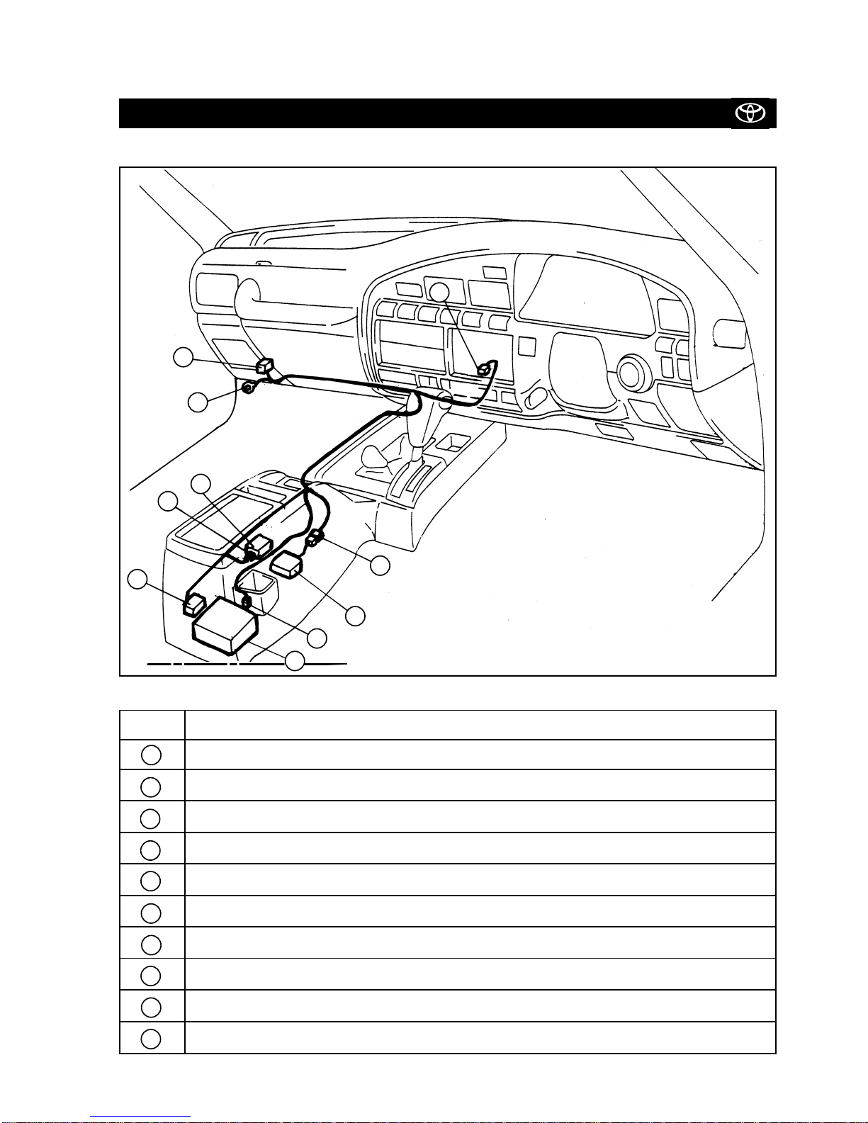
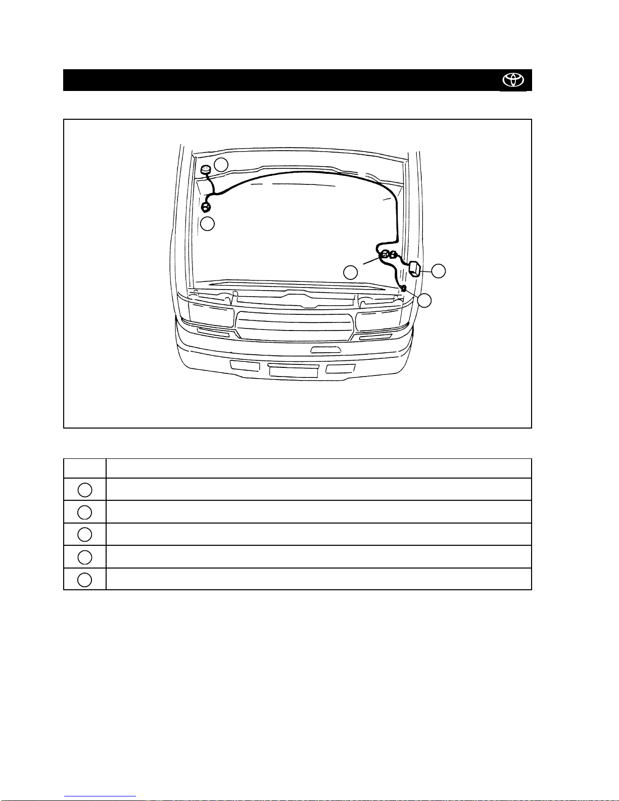
System Layout and Wire Harness Outline
• Main .................................................................................................................................................................... 7
• Engine ................................................................................................................................................................. 8
Connector Arrangement of the TVSS Fitting Kit (Pin View) ............................................................................ 9
TVSS Installation Procedures
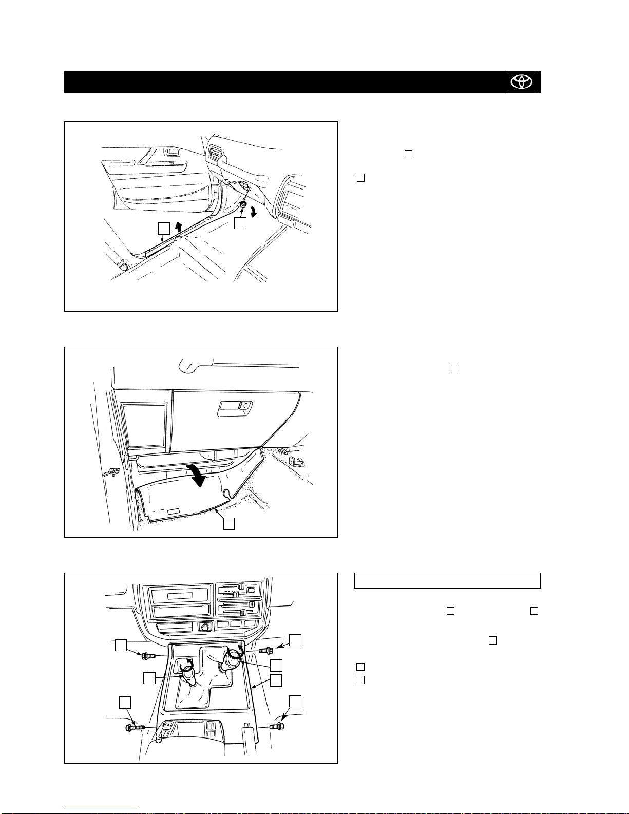
• Vehicle Disassembly (Passenger Compartment) ................................................................................................ 10
• Wire Harness (Main) Installation ........................................................................................................................ 13
• Mounting the Status Monitor .............................................................................................................................. 15
• Mounting the Radar Sensor ................................................................................................................................ 16
• Mounting the Glass Breakage Control Unit ......................................................................................................... 18
• Vehicle Disassembly (Engine Compartment) ...................................................................................................... 20
• Mounting the Siren ............................................................................................................................................. 23
• Wire Harness (Engine) Installation ...................................................................................................................... 25
• Mounting the Hood Switch ................................................................................................................................. 28
• Setting the TVSS ECU Dip Switches and Testing the System ............................................................................. 29
• Mounting the TVSS ECU ..................................................................................................................................... 30
• Mounting the Glass Breakage Sensor ................................................................................................................. 32
• Attaching the Stickers ......................................................................................................................................... 34