Setra Systems MicroCal User manual

User Manual
MicroCal™
Advanced Modular Pressure Calibrator
800.257.3872
setra.com


3
Table of Contents
1.0 SAFETY INSTRUCTIONS...................................................................................5
2.0 INTRODUCTION...............................................................................................6
3.0 STANDARD EQUIPMENT BREAKOUT..................................................................7
4.0 OPERATING FEATURES
4.1 MICROCAL............................................................................................8
4.2 PORTABILITY.........................................................................................8
4.3 CALIBRATOR SCREEN OVERVIEW..........................................................9
5.0. CALIBRATOR SETUP
5.1 USER INTERFACE PANEL.....................................................................11
5.2 BATTERY CHARGING...........................................................................11
5.3 REPLACE & INSTALL BATTERY..............................................................12
5.4 REFERENCE INSTALLATION.................................................................14
5.5 GETTING STARTED..............................................................................14
6.0 MICROCAL INTERFACE SCREENS
6.1 APPLICATION DEFINITIONS................................................................16
6.2 REAL TIME: GENERAL.........................................................................16
6.21 REAL TIME: DIAL GAUGE..............................................................17
6.22 REAL TIME: PSWITCH .................................................................17
6.23 REAL TIME: EXPERT SYSTEM........................................................17
6.3 RUN TEST: GENERAL...........................................................................18
6.31 RUNTEST: DIAL GAUGE................................................................19
6.32 RUNTEST: PSWITCH ...................................................................19
6.33 RUNTEST: DITHER CONTROL PAGE...............................................20
6.34 RUN TEST: EXPERT SYSTEM...........................................................21
6.4 TEST SETUP: GENERAL.......................................................................22
6.41 TEST SETUP: DIAL GAUGE .............................................................23
6.42 TEST SETUP: PRESSURE SWITCH...................................................23
6.5 UUT UNIT UNDER TEST SETUP: GENERAL.......................................24
6.51 UUT SETUP: DIAL GAUGE..............................................................28
6.52 UUT SETUP: PSWITCH .................................................................28
6.53 UUT SETUP: EXPERT SYSTEM........................................................29
6.6 SYSTEM .............................................................................................30

4
7.0 UNIT UNDERTEST CONNECTION.....................................................................35
8.0 CALIBRATING/TESTING ATRANSDUCER/TRANSMITTER .................................35
9.0 MICROCAL MANAGER INTERFACE
9.1 SETUP FOR MICROCAL CONNECTION ................................................38
9.2 GRAPHICAL USER INTERFACE SETUP ...............................................39
9.3 TEST RESULTS DATA...........................................................................43
10.0 MICROCAL SPECIFICATIONS
10.1 MEASUREMENT................................................................................46
10.2 CONTROL..........................................................................................46
10.3 GENERAL SPECIFICATIONS...............................................................46
11.0 ADDITIONAL RESOURCES
11.1 GLOSSARY OF TERMS........................................................................47
11.2 INTERPRETING PRESSURETRANSDUCER SPECIFICATIONS..............48
12.0 SPARE PARTS & ACCESSORIES....................................................................52
13.0 RECALIBRATION &WARRANTY INFORMATION..........................................53

5
1.0 SAFETY INSTRUCTIONS
Use the calibrator only as specied in the manual, otherwise the protection provided
may be impaired.
Do not operate the calibrator in explosive gas, vapor or dust environments.
The calibrator is designed to operate from 14.4VDC removable Lithium Ion battery
source or from the AC adaptor that is included. Do not use AC adapters, chargers or
batteries other than those supplied by Setra.
If supplying external excitation to the Unit UnderTest in a measure mode, do not exceed
30VDC.
There are no user serviceable parts internally, removing the internal cover will void
warranty. Return the unit to the factory for re-certication or repair.
BEST PRACTICES FOR CALIBRATOR OPERATION:
Use the shortest length of tubing from the calibrator to the Unit UnderTest, during
pressure testing avoid vibration of the tubing.
Avoid movement of the calibrator during operation, avoid locating in a high vibration
environment.
Keep reference door closed when not changing modules.
Allow the calibrator to warm-up for 30 minutes before use. The calibrator can be turned
on during transport.
6
2.0 INTRODUCTION
DOCUMENTING PROCESS CALIBRATOR:
The Setra MicroCal is a pressure generating, modular pressure documenting calibrator.
The calibrator has been designed and optimized to meet the needs of our customers for
a capable system for the calibration, troubleshooting and documentation of very low
pressure measuring information.
The design of the MicroCal exploits years of experience in the calibration of Setra trans-
ducers, as well as NASA patented and Setra exclusive licensed technology.
Major Features:
• 7”Touchscreen Display, capable of storing thousands of Units Under
Test (UUT) data les.
• Portable, battery powered system, capable of full operation throughout
a typical work day.
• Closed loop pressure control which is immune to the eects of ambient
pressure perturbations, (doors closing, people moving around).
• Very low internal reference pressure standards, which are selectable to
match customer needs.
• Auto zero pressure“tare”function.
• Ability to source power to the UUT, or use external power supply.
• High resolution pressure control capable of precise generation and
pressure control in the micro inch of water column pressure ranges.
• Leak testing
• High accuracy MCPM modular pressure references give exibility and
accuracy to the end customer.
• Modular battery to ensure all your calibrations are able to be completed.
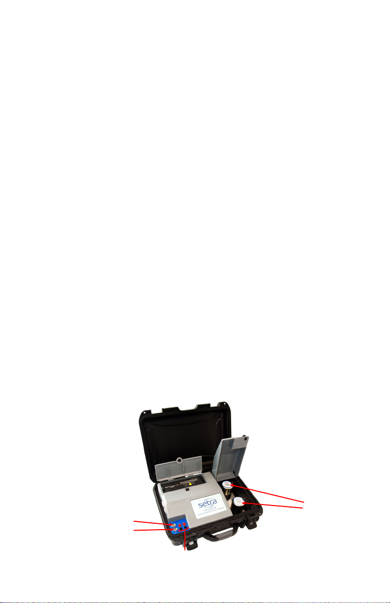
Diagram 1
High Pressure Port
Electrical Connections
for Unit UnderTest
Low Pressure Port
Reference
Modules

7
3.0 STANDARD EQUIPMENT BREAKOUT
THE ITEMS BELOW ARE INCLUDED INYOUR CALIBRATOR:
Diagram 2
AC Power Adapter
Pneumatic Fittings
&Tubing
ElectronicTest Lead Kit
Calibration Certicate
User Manual
Calibrator
Rechargeable
Battery
Diagram 3
Pressure Module Box
What’s Included:
Up to 4 Pressure Reference
Modules Per Box
Accessory Box
What’s Included:
User Manual
Rechargeable Battery
AC Power Adapter
ElectronicTest Kit
Pneumatic Fittings &Tubing

8
4.0 OPERATING FEATURES
4.1 THE MICROCAL PERFORMSTHE FOLLOWING MAJOR FUNCTIONS
• User interface for setups, display and storage.
• Data transfer to and from MicroCal Manager Database.
• Monitors battery voltage
• Stores data for UUT, test proles and test results.
• ISO Certication
4.2 PORTABILITY - CALIBRATOR IS FULLY PORTABLE AND POWERED BY
• 24VDC external, 120/240 power adapter included
• Using the removable battery which has been designed for operation
throughout a typical workday after a full charging cycle. The Li-Ion battery israted at
14.4VDC, 6.6 Amp hour (AH).

9
4.3 CALIBRATOR SCREEN OVERVIEW
Real-Time Screen
• Displays installed references
• Actively read Applied Pressure, UUT Output & %
Error
• Apply user selectable pressure, for manual cali-
bration
• Enable either Control (apply pressure) or Monitor
(read pressure from system)
• Select UUT proles
Run Test Screen
• Select UUT Proles
• Select Test Setup
• Automatically run pressure test based on UUT and
test setup selections
• Store and recall“As-Found”&“As-Left”test results
Test Setup Screen
• Create unique test proles; Ascending, Descend-
ing, Both or Custom
• Dene number of test points

10
UUT Setup Screen
• Create unique site specic UUT ID’s
• Select a“Test Setup”to associate to UUT
• Dene the parameters of a UUT that will be tested
• The UUT setup/selection is utilized across multiple
screen functions
System Screen
• Communications software revisions of the
MicroCal
• Visual indication of battery level
• Set default settings for the unit
• Select engineering units to be used across all
functions
11
5.0 CALIBRATOR SETUP
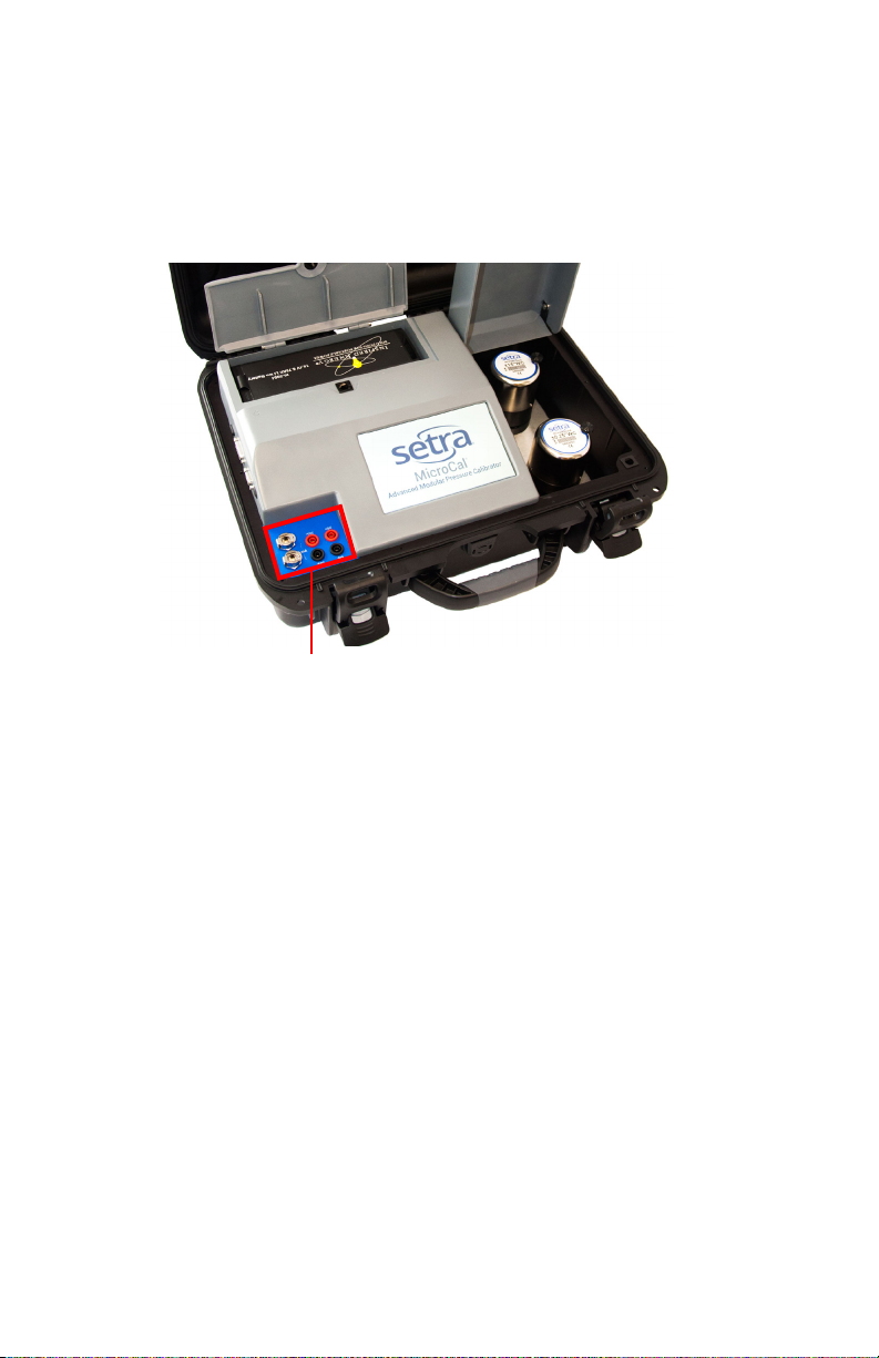
5.1 USER INTERFACE PANEL
The user interface panel includes the pressure and electrical connections to the unit
under test. (See Diagram 4)
5.2 BATTERY CHARGING
The MicroCal is assembled, calibrated and tested at the factory. The battery, as received,
will be in a partially charged state. Before operation please be sure to fully charge the
battery to get maximum portable use of the device.
TO CHARGE THE BATTERY:
• Connect the AC power adapter (AC adapter is shipped in Accessory Box, see Diagram
3) to AC supply connector on back of unit or use optional desktop charger (869974-G)
• Initial battery charging will take approximately 2-4 hours.
Diagram 4
User Interface Panel
12
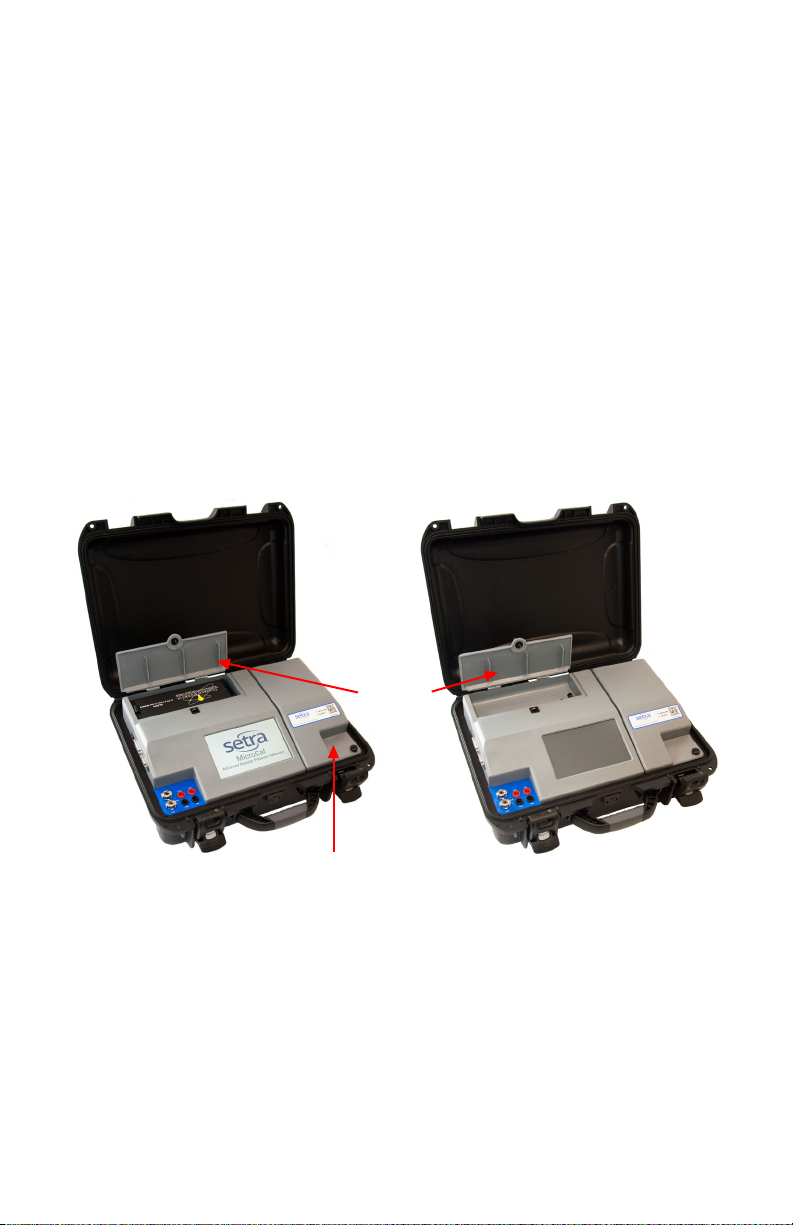
5.3 REPLACE & INSTALL BATTERY
Open Battery Door: Rotate the black knob counter-clockwise and pull up on the battery
door.
Remove Installed Battery: Pull tab and lift out battery.
Install Charged Battery: Align pins inside the battery compartment with the receptacle
on charged battery. Place battery into compartment unit the battery is fully seated.
Close Battery Door: Rotate the black knob counter-clockwise, rotate the door to the
closed position, and release knob to lock into position.
Battery Door
Reference Door
Diagram 5
13
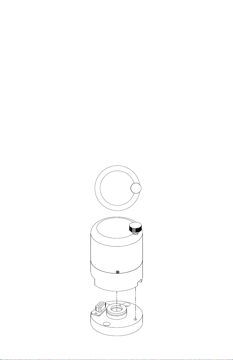
5.4 REFERENCE INSTALLATION: CHANGING MICROCAL PRESSURE MODULE (MCPM)
(Diagram 6)
The MicroCal is designed with 2 pressure reference bases. These MCPM reference mod-
ules can be added in eld into either base. Software will automatically detect installed
reference.
Open Reference Door (See Diagram 6): Rotate the black knob counterclockwise and pull
up on the reference door.
Remove Installed Reference: Loosen black thumbscrew (3 o’clock position) by rotating
counter-clockwise.
Install New Reference: Align the MCPM reference so the knob is in the 3 o’clock position.
Press down on the MCPM housing until fully seated. Tighten black thumbscrew by
rotation clockwise.
Close Reference Door: Pull the reference door down and rotate the black knob counter
clockwise.
Diagram 6

14
5.5 GETTING STARTED
1. Open calibrator top.
2.Turn on calibrator power by toggling the power button towards the back of the unit
(power switch on left side of the calibrator see Diagram 7).
3. Once calibrator is powered up, re-zero function begins automatically. Please wait for
completion. (User will hear operation of solenoid valves and stepper motor).
4. Software will startup with Real-Time Page. Select desired UUT from drop-down to
begin performing calibrations. (See Section 6.5 to setup new UUT proles)
Diagram 7
Power
Switch
RS232
Expert System Interface

15
Diagram 8: Real-Time Screen
Applied
Pressure
UUT
Output
Terminal
Based Error
Installed
Pressure References
Navigation Buttons
Bar Graph of Error
% FS
Excitation to Unit
UnderTest
Access Stored UUT
Proles
Vents Pressure to Atmosphere
Snapshot of Data
TARES Internal Pressure
Standards
Enable Monitor Only
Mode ( No Pressure Control)
Enables Pressure
Control
Go to Pressure
Macro Buttons

16
6.0 MICROCAL INTERFACE SCREENS
The MicroCal Interface is tab-based, split into 5 major sections at the bottom of the
screen.
6.1 APPLICATION DEFINITIONS
General:This describes operation for the broadest range of applications.
Dial Gauge: Departures from general operation for Dial Gauge calibration.
P-Switch: Departures from general operation for Pressure Switch calibration.
Expert System: Departures from general operation for Expert System calibration.
6.2 REALTIME: GENERAL
Screen Instructions (Diagram 9):
RealTime page is constantly updating and is used to see the output and pressure being
applied for calibration purposes and test purposes (acts as a digital indicator).
APPLIED PRESSUREWINDOW: Displays system pressure.When a new pressure set point
is selected, the text will turn yellow while pressure is outside of target control band (Re-
quired control stability for UUT). Text will turn green when target pressure is reached.
SETPOINT: The go to pressure macro buttons are congured by the selected UUT pressure
range. These can be used to manually step through pressure setpoints for calibration or
when making manual adjustments. For all units, the top most button will display the
UUT’s -FS PressureValue.The bottom-most button will display the UUT’s +FS Pressure
Value. Pressing any of the buttons enters the pressure value on the button into the
target pressure window and calls the“Go to Pressure”function.
VENT: Opens both positive and negative pressure ports to each other and atmosphere.
TARE: Zeros out internal pressure standard and re-zero’s mechanical components in
controller.
GOTO PRESSURE: Calls controller to generate pressure point set in pressure target box.
HOLD: Stops any process in action.
MONITOR: Switches calibrator into monitoring mode. This allows calibrator to be used
as pressure measurement device.
CONTROL: Switches calibrator into control mode. This allows the calibrator to be used for
pressure control and as a measurement device.
Error Graph is an auto-scaling display of the present error of the UUT’s output as com-
pared to the applied pressure.The red bars on the graph represent the UUT’s accuracy
specication limits.The labels will display the present range of the graph. The arrow
showing the error will turn red when the error is outside of tolerance.

17
6.21 REALTIME: DIAL GAUGE
Dierences from General (Diagram 9):
-Output and Error windows hidden.
-Bar Graph of Error is hidden.
6.22 REAL TIME: PSWITCH
Dierences from General (Diagram 9):
-Output window changes to OPEN/CLOSE indicator/capture window
-Error window changes to OPEN/CLOSE indicator/capture window
-Bar Graph of Error is hidden.
6.23 REAL TIME: EXPERT SYSTEM
Dierences from General (Diagram 9):
-Monitor Only/Control button locked out, automatically controlled by the process head
connection/disconnection.
Diagram 9
Applied
Pressure
UUT
Output
Terminal
Based Error
Installed
Pressure References
Navigation Buttons
Error Graph
Excitation to Unit
UnderTest
Access Stored UUT
Proles
Vents Pressure to
Atmosphere
Stops Pressure Control
TARES Internal
Pressure Standards
Enables Pressure
Control
Enable Monitor Only
Mode ( No Pressure
Control)
Go to Pressure
Macro Buttons

18
6.3 RUNTEST: GENERAL
Screen Instructions (Diagram 10):
1. Tap the RUN TEST tab at the bottom of the page.
2. Select desired UUT from the drop down box at the top of the page. If desired UUT is not
there, see Page 24 for creating a new UUT.
3. View the TEST drop down box and conrm that prole selected is the desired pressure
test prole, if not, select desired prole from drop down list or if desired test prole is
not there, see Page 22 for creating a new test setup.
4. Select AS FOUND or AS LEFT radio button.
5. Tap TARE and wait until completed. This zeroes the ref. unit.
6. Tap RUN button.
7. To stop a test in process, tap the STOP button. This will stop and
cancel the test.
8. Target pressure will be generated and data will be automatically
recorded at each pressure point. Note: If the DisplayTest Results in Graph Option is selected (see
Edit Defaults page) - a graph will appear displaying pressure vs. error after the pressure sequence
has been completed (Diagram 11).
9. To record data -Tap RECORDTEST RESULTS button
Note: RecordTest Results Button has 3 states indicating the save status of test results. When no test
results are available to save, the button reads“No Results To Save.” When results on screen have
been saved, the button will change to“Test Results Saved.” After a test is complete and before the
data is saved, the button will read“RecordTest Results.”
10. To review data - Tap REVIEW TEST RESULTS button
11. To expand/collapse theTest Prole/Results window, double tap anywhere insideTest Results
list.
Diagram 10
Record Data
Target Pressure
Prole ID
TestTab
Review Data
Do Test
Unit UnderTest
(UUT) Identity
Re-Zero
Stop
As Found/As Left
Test Selection
Test Prole/
ResultsWindow

19
6.31 RUNTEST: Dial Gauge
Dierences from General (Diagrams 10 & 11):
-Pressing RUN button brings up separate test page with dither control (Diagram 12).
-Output columns removed fromTest Prole/Results window.
6.32 RUNTEST: PSWITCH
Dierences from General (Diagrams 10 & 11):
-Pressing RUN button brings up separate test page with dither control (Diagram 12).
-Output columns removed fromTest Prole/Results window.
-O/C column added to indicate the state of the pressure switch.
O - Open
C - Closed
Diagram 11

20
6.33 RUNTEST: DITHER CONTROL PAGE (Manual Pressure Incrementing)
Screen Instructions (Diagram 12):
Test Point Indicator: Displays present test point number.
Target Pressure: Displays present test point target pressure.
Eng Units Display: Displays pressure units.
Pressure Display Window: Displays present pressure during test.
OPEN/CLOSE Indicator: Available only with P-Switch, indicates open/closed status of
switch.
Take Data Button: Forces data collection for Dial Gauge. Tells software that the UUT is
indicating the present target pressure.
Target Pressure Button: Set pressure target to original target dened by test prole for
present test point.
Vent Button: Stops the test in progress and vents MicroCal pressure ports to atmosphere.
Halt: Pauses pressure control. Leaves system closed to allow for quick re-acquisition of
target pressure.
Set PointWindow: Displays present set point for the MicroCal pressure controller.
Updates when test point number is changed, or when +/- dither controls are used. Also,
allows user entry.
GO Button: Updates pressure target within MicroCal to that displayed in the set point
window. Starts pressure control.
- FINE Button: Decreases pressure set point by 0.1% of UUT span.
+ FINE Button: Increases pressure set point by 0.1% of UUT span.
- COARSE: Decreases pressure set point by 1% of UUT span.
+ COARSE: Increases pressure set point by 1% of UUT span.
Cancel Button: Stops test in progress and erases any data taken. Leaves unit in vented
state.
Diagram 12
Take Data Button
Vent Button
Cancel Button
Pressure
Display
Window
OPEN/CLOSED
Indicator
(P-Switch Only)
Set PointWindow
Halt Button
GO Button
+ FINE Button- FINE Button
+ COURSE Button- COURSE Button
Target
Pressure
Test Point
Indicator Eng. Units
Display
Table of contents


