Chopin QUATUOR User manual

20, avenue Marcellin Berthelot - Z.I. du Val de Seine
92396 Villeneuve La Garenne cedex - France
www.chopin.fr
www.chopinservice.com
QUATUOR
User’s manual
10/2016
Phone: +33 1 41 47 50 33
Fax: +33 1 47 47 17 13 (SAV)
E-mail: [email protected]

QUATUOR
2 User’s manual
10/2016

QUATUOR
3
User’s manual
10/2016
IMPORTANT
The technical elements that constitute this manual (text and illustrations) are not contractual,
their only target being to bring assistance for using the Quatuor.
Use, duplication or disclosure of subject data, for any purpose other than relating to the use or
servicing of the equipment, is strictly prohibited without the written authorisation of Chopin
Technologies.

QUATUOR
4 User’s manual
10/2016
QUATUOR
5
User’s manual
10/2016
Siège de Chopin Technologies
20 avenue Marcellin Berthelot, 92396 Villeneuve-la-Garenne Cedex, France
Tél. : +33 1 41 47 50 90 – Fax. : +33 1 47 92 02 44
S.A. au capital de 1 821 700 Euros – R.C.S. Nanterre – Siret 403 156 441 00020 – APE 332 B – TVA FR 03 403 156 441
DECLARATION OF CONFORMITY
We Chopin Technologies, address as below,
declare under our sole responsibility that the following Apparatus :
Quatuor
When installed and used in accordance with the instructions in the Product Manual,
is in conformity with the following standards :
the EEC directive “Low Voltage“ 2006/95/CE.
the EEC directive “Electromagnetic compatibility“ 2004/108/CE
Emmanuel LECOMTE
Conformance officer
Chopin Technologies
Daniel VILHIES
Technical director
Chopin Technologies
Date :
10/2010

QUATUOR
6 User’s manual
10/2016

QUATUOR
7
User’s manual
10/2016
Table of contents
Introduction . . . . . . . . . . . . . . . . . . . . . . . . . . . . . . . . . . . . . . . . . . . . 9
Section 1 Installation and setup . . . . . . . . . . . . . . . . . . . . . . . 11
1. Unpacking . . . . . . . . . . . . . . . . . . . . . . . . . . . . . . . . . . . . . . . . . . . . 13
2. Composition . . . . . . . . . . . . . . . . . . . . . . . . . . . . . . . . . . . . . . . . . . 14
3. Installation . . . . . . . . . . . . . . . . . . . . . . . . . . . . . . . . . . . . . . . . . . . . 15
4. Connection of other units . . . . . . . . . . . . . . . . . . . . . . . . . . . . . . . . 17
5. IElectric connection . . . . . . . . . . . . . . . . . . . . . . . . . . . . . . . . . . . . . 18
6. Powering up the unit . . . . . . . . . . . . . . . . . . . . . . . . . . . . . . . . . . . . 18
Section 2 Normal use . . . . . . . . . . . . . . . . . . . . . . . . . . . . . . . 21
1. Precautions . . . . . . . . . . . . . . . . . . . . . . . . . . . . . . . . . . . . . . . . . . . 23
2. Operating modes . . . . . . . . . . . . . . . . . . . . . . . . . . . . . . . . . . . . . . . 24
3. The touch screen . . . . . . . . . . . . . . . . . . . . . . . . . . . . . . . . . . . . . . 25
4. Test cycle . . . . . . . . . . . . . . . . . . . . . . . . . . . . . . . . . . . . . . . . . . . . 26
5. Comments . . . . . . . . . . . . . . . . . . . . . . . . . . . . . . . . . . . . . . . . . . . . 30
Section 3 Operation and configuration . . . . . . . . . . . . . . . . . 31
1. Principle . . . . . . . . . . . . . . . . . . . . . . . . . . . . . . . . . . . . . . . . . . . . . 33
2. Safety recommendations . . . . . . . . . . . . . . . . . . . . . . . . . . . . . . . . . 35
3. Screens of the QUATUOR . . . . . . . . . . . . . . . . . . . . . . . . . . . . . . . 36
Section 4 Making adjustments and calibrations . . . . . . . . . . 49
1. Choosing the sieves . . . . . . . . . . . . . . . . . . . . . . . . . . . . . . . . . . . . 51
2. Case of the sunflower sieve with cover (FADT-65) . . . . . . . . . . . . . 55
3. Creating or modifying a calibration . . . . . . . . . . . . . . . . . . . . . . . . . 57
Section 5 Maintenance . . . . . . . . . . . . . . . . . . . . . . . . . . . . . . 59
1. Periodic maintenance . . . . . . . . . . . . . . . . . . . . . . . . . . . . . . . . . . . 61
2. Problem solving . . . . . . . . . . . . . . . . . . . . . . . . . . . . . . . . . . . . . . . . 62
3. Changing fuses . . . . . . . . . . . . . . . . . . . . . . . . . . . . . . . . . . . . . . . . 65
4. Calibrating the screen . . . . . . . . . . . . . . . . . . . . . . . . . . . . . . . . . . . 66
5. Calibrating the scales . . . . . . . . . . . . . . . . . . . . . . . . . . . . . . . . . . . 67
6. Replacement recommended frequency of parts having
an influence on the result . . . . . . . . . . . . . . . . . . . . . . . . . . . . . . . . 69
Appendix keyboard shortcuts . . . . . . . . . . . . . . . . . . . . . . . . 71

QUATUOR
8 User’s manual
10/2016
QUATUOR
9
User’s manual
10/2016
INTRODUCTION
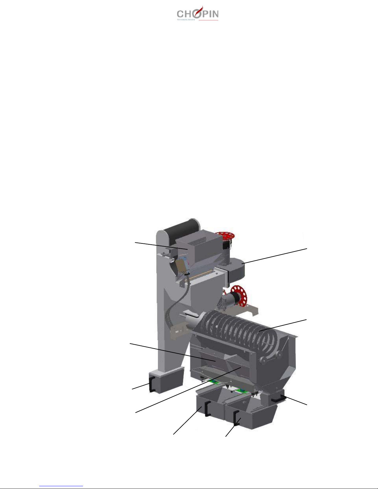
■ Principle :
■ The function of the Quatuor is to provide the percentage of good
grain, impurities and broken grain from a given sample.
■ The test cycle starts with a debearding (optional module), and the
sample weighing (scale B1).
■ The apparatus proceeds then to the elimination of lightest parti-
cles (dust).
■ The rest of the sample falls then into cylindrical sieves and is
sorted into 3 categories:
❏ broken grain,
❏ good grain,
❏ big impurities.
■ Good grain and broken grain are weighed separately by scales
B2 and B3 respectiveley.
blower
sieves
weighing
hopper B1
scale B3
light impurities
broken grain good grain
big
impurities
scale B2

QUATUOR
10 User’s manual
10/2016
■ Within 1 mn 30 sec, the QUATUOR:
❏ sorts the sample into 4 categories (light impurities, broken grain,
good grain, big impurities),
❏ calculates the percentage of good grain, broken grain and impuri-
ties + broken grain.
■ Overall characteristics:
❏ The QUATUOR has a memory able to contain 21 user-program-
mable calibrations.
❏ A parallel output allows the connection of a printer with a Cen-
tronics interface.
❏ An RS232 serial interface allows the connection of a PC compati-
ble.
❏ A mini DIN port allows the connection of a standard keyboard.
❏ Power supply: 230 V - 50/60 Hz - 210 W
❏ Noise level: < 70 dB
❏ Dimensions:
Length = 500 mm; Depth = 730 mm; Height = 940 mm
❏ Net weight: 50 kg
■ Environment:
❏ Inside use.
❏ Storage temperature: — 20°C to + 60° C
❏ Operating temperature: 2°C to 45° C
❏ Hygrometry: HR 85% at 40°C
❏ Supply voltage tolerance: < ± 10%
❏ Pollution level according to EN 61010: 2
❏ Installation class according to EN 61010: II
(for transitional over voltage)
❏ Utilisation area (dust hazard risk): all areas except areas rated
20, 21 and 22.
■ Fuse :
Fuse 5x20 T 2A 250V

QUATUOR
11
User’s manual
10/2016
Section 1 INSTALLATION AND SETUP

QUATUOR
12 User’s manual
10/2016

QUATUOR
Section 1 Installation and setup 13
User’s manual
10/2016
Section 1. Installation and setup
1. Unpacking ■ The apparatus is packed in a dedicated packing, that we recom-
mend you to keep for future use (transfer from one location to
another one, periodic service, etc.).
This packing contains the QUATUOR with accessories and the
user’s manual.
■ The QUATUOR shall be handled by two persons. See handling
areas on figure below.

QUATUOR
14 Section 1 Installation and setup User’s manual
10/2016
2. Composition The QUATUOR (1) is supplied with:
■ 1 pen for touch-screen (2),
■ 1 one-litre container (3),
■ 1 power cord (4),
■ a distribution screw (5), with an optional sieve (see installation
page 53),
■ a brush (6), to be installed before the first use.
1
4
3
5
2
6
QUATUOR
Section 1 Installation and setup 15
User’s manual
10/2016
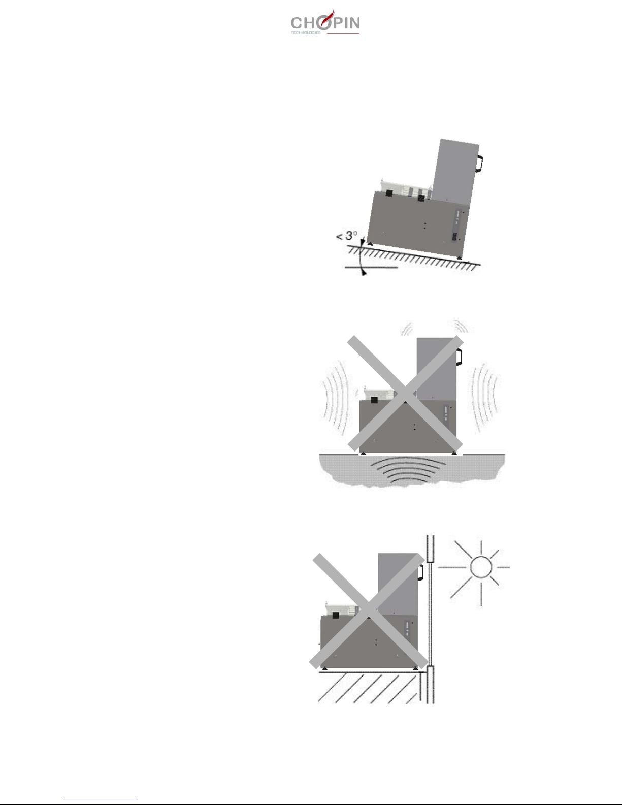
3. Installation 3.1 Generalities
■ Install the QUATUOR on a stable and horizontal surface. Maxi-
mum tilt angle: 3°.
■ Avoid locations subjected to vibrations (machines, trains, trucks,
etc.): this may cause wrong weight measurements.
■ Avoid placing the QUATUOR behind a window pane exposed to
sunshine during several hours.
QUATUOR
16 Section 1 Installation and setup User’s manual
10/2016
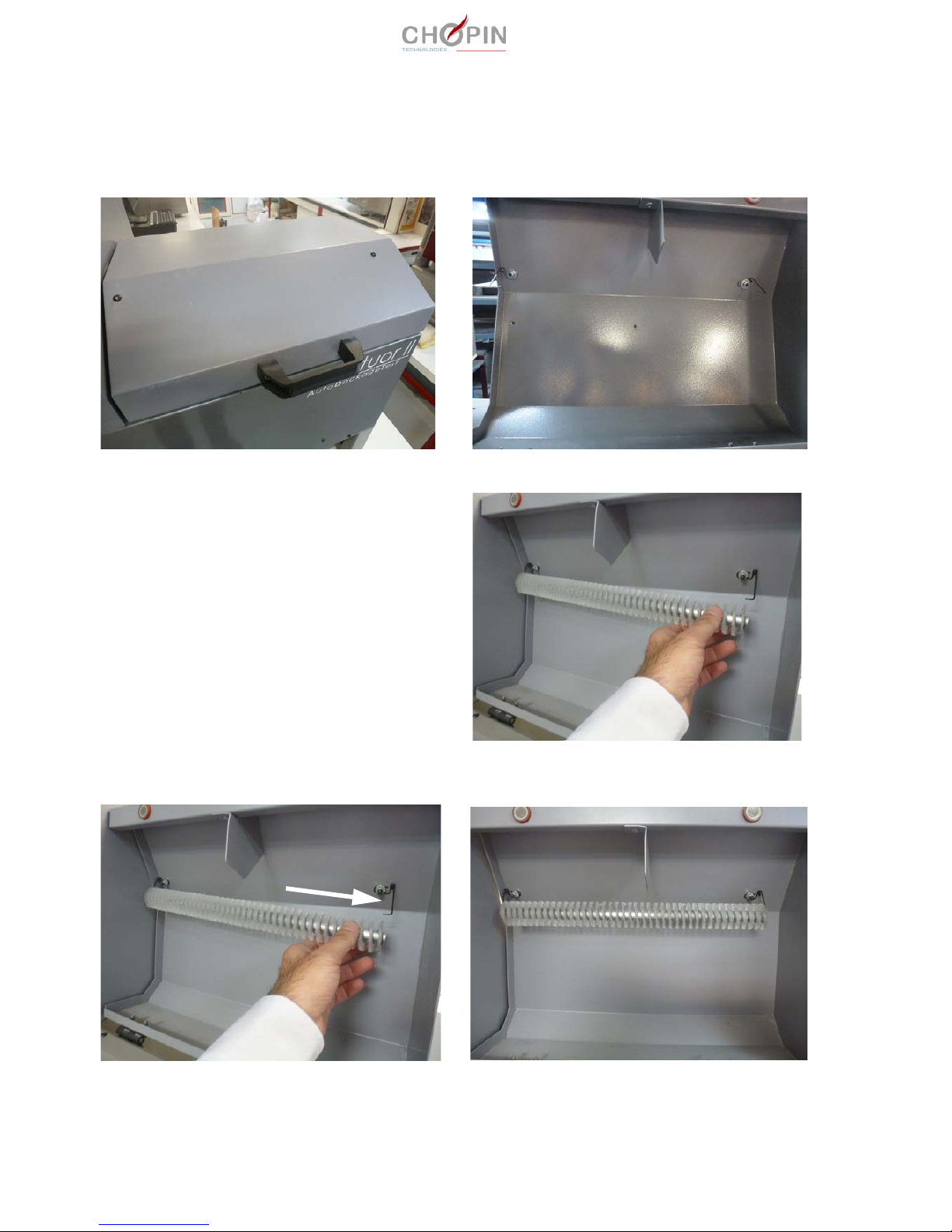
3.2 Installing the brush
1. Open the cover.
2. Insert the brush on the first spring.
3. Push the second spring with the hand and insert the brush on
the second spring.
QUATUOR
Section 1 Installation and setup 17
User’s manual
10/2016
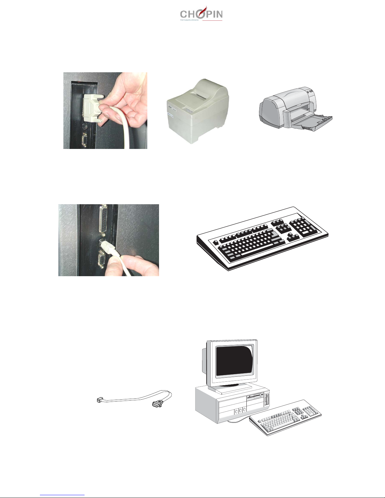
4. Connection of other
units
■ The printer
A standard or ticket-type printer can be connected to the QUATUOR
through the Centronics parallel port.
■ The keyboard
A keyboard can be connected to the QUATUOR through the mini
DIN serial port.
This will enable the entering of alphanumeric characters in certain
menus.
■ A computer
A computer can be connected on the RS232 port of the QUATUOR.
Contact Chopin Technologies.
or
QUATUOR
18 Section 1 Installation and setup User’s manual
10/2016
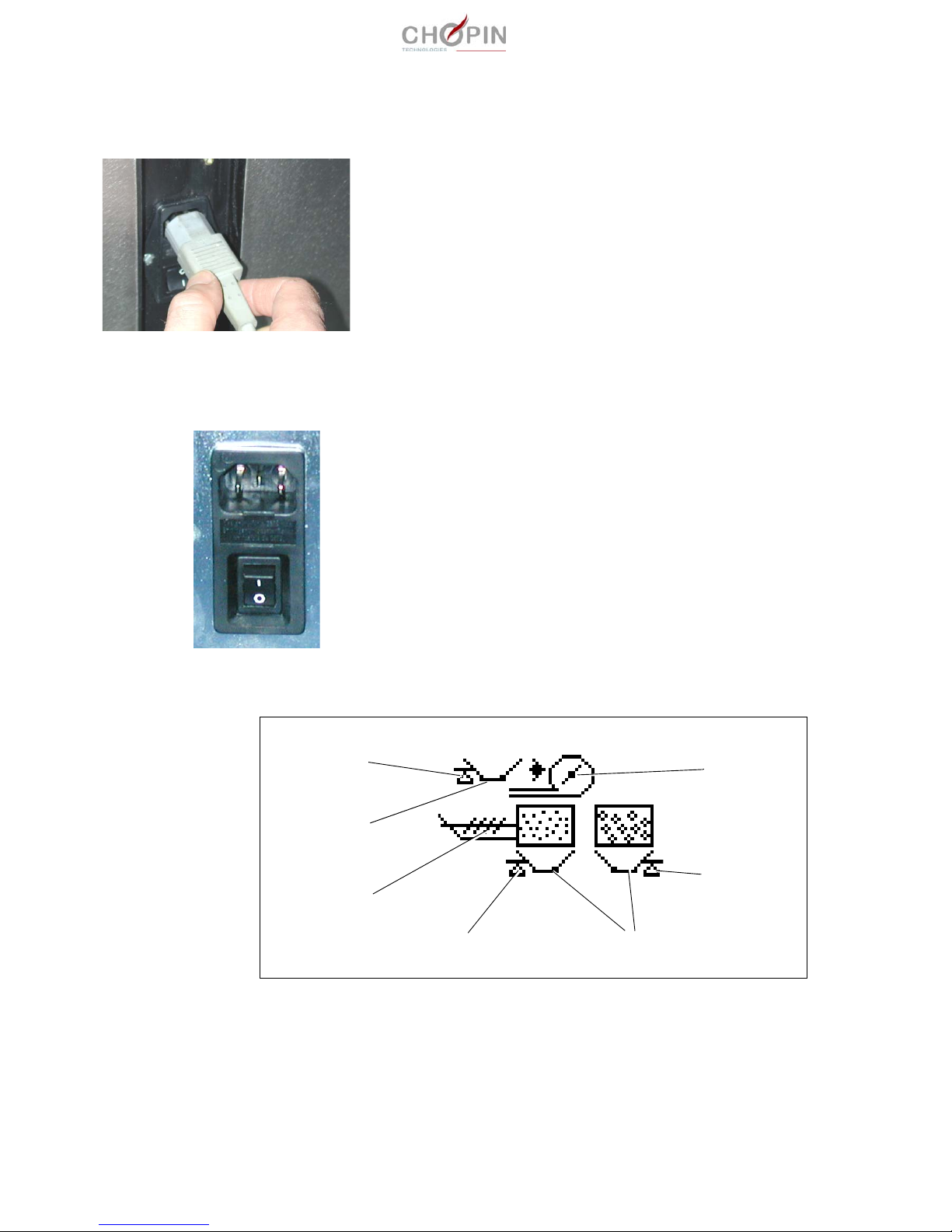
5. IElectric connection The QUATUOR is an electronic apparatus which must be connected
to an electrical network equipped with an Earth terminal. Above all,
verify the condition of this connection.
In addition, the electrical network must be equipped with an RDD
(Residual Differential Device) of the AC grade with a sensitivity
30 mA.
For the connection to the network, use the power cord provided with
the QUATUOR.
The mains plug and the I/O switch are located at back of the appa-
ratus.
6. Powering up the unit ■ Turn the On/Off switch to ON. The QUATUOR runs a self-test
sequence, checking most of its functions (memories, INIT parame-
ters, motors, scales, etc.); during this sequence, which lasts 1 min
approx., all commands (by means of the touch screen or a key-
board) are inactive.
■ During this self-test sequence are displayed:
❏ the name of the apparatus,
❏ the software version,
❏ successively the different test phases described in table below
.
blower
sieve control
M4
B1
B3
M1
B2

QUATUOR
Section 1 Installation and setup 19
User’s manual
10/2016
■ If an anomaly is detected during this sequence, an error message
is displayed. In this case switch the apparatus Off then On. If the
message is still present, refer to chapter "Problem solving"
page 62.
■ After this initialization sequence, the QUATUOR is ready, and the
the main menu is displayed; it mentions the name of the last grain
selected before apparatus power-off, and allows to choose the oper-
ation to initiate by simply selecting the corresponding touch icon.
■ The user may so :
❏ modify the selected grain,
❏ initiate a test sequence of a grain sample,
❏ access to other menus whose content is detailed in chapter "The
maintenance menu" page 41.
Phase Meaning
1 Tare on scale B1
2Functional test of M1 (grain feeding trap door) with
position reading of stops
3 Functional test of M2
4Functional test of the debearder, then functional
test of M3
5 Tare on scale B1
6 Functional test of the blower
7If tare B1 phase 1 <> tare B1 phase 5, then open-
ing of M1
8Functional test of sieve control, and if tare B1
phase 1 <> tare B1 phase 5, then waiting 180sec
9 Functional test of M4 (emptying trap doors)
10 Tare on scales B2 and B3

QUATUOR
20 Section 1 Installation and setup User’s manual
10/2016
Table of contents
Other Chopin Test Equipment manuals


Popular Test Equipment manuals by other brands


Redtech
Redtech TRAILERteck T05 user manual

Venmar
Venmar AVS Constructo 1.0 HRV user guide

Test Instrument Solutions
Test Instrument Solutions SafetyPAT operating manual

Hanna Instruments
Hanna Instruments HI 38078 instruction manual

Kistler
Kistler 5495C Series instruction manual

Waygate Technologies
Waygate Technologies DM5E Basic quick start guide

StoneL
StoneL DeviceNet CK464002A manual

Seica
Seica RAPID 220 Site preparation guide

Kingfisher
Kingfisher KI7400 Series Training manual

Kurth Electronic
Kurth Electronic CCTS-03 operating manual

SMART
SMART KANAAD SBT XTREME 3G Series user manual

Agilent Technologies
Agilent Technologies BERT Serial Getting started