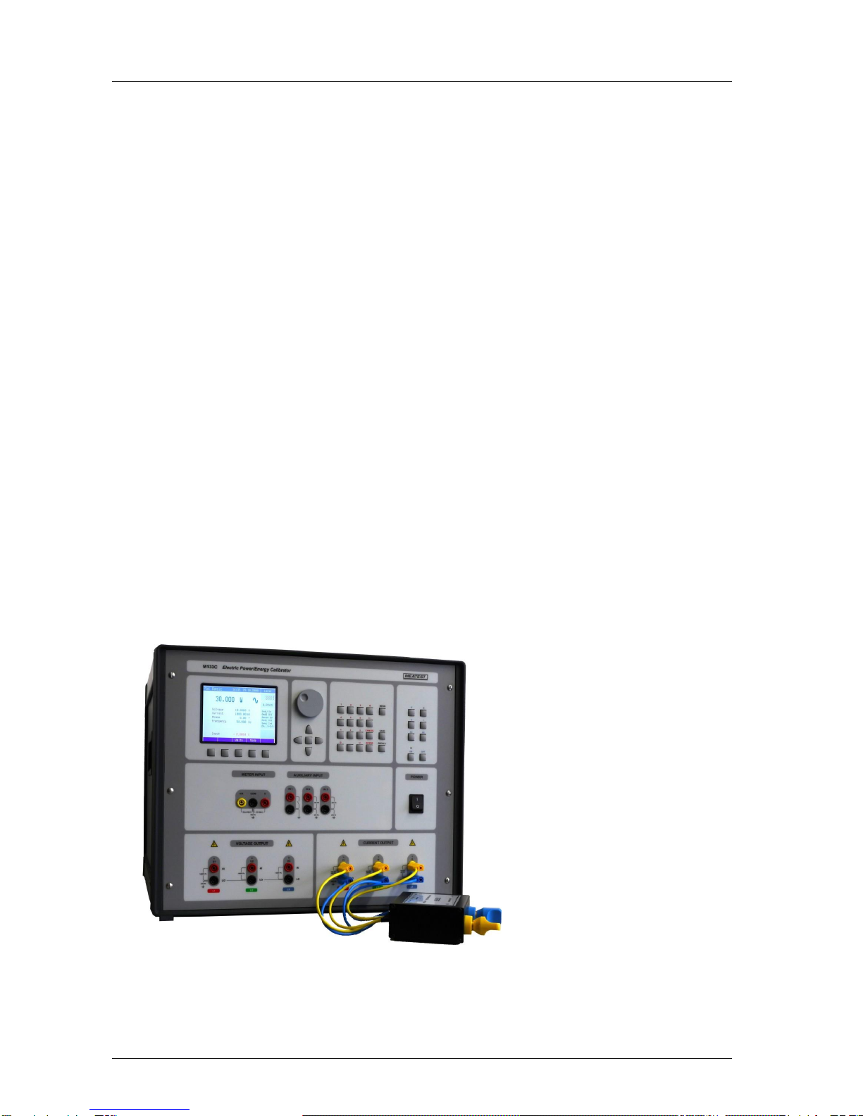
M133C Electric Power/Energy Calibrator MEATEST
3 Version 30 Operation manual
Content
1Basic information.......................................................................................................................5
2Preparation for operation..........................................................................................................6
2.1 Inspecting package contents, selecting the installation location ....................................6
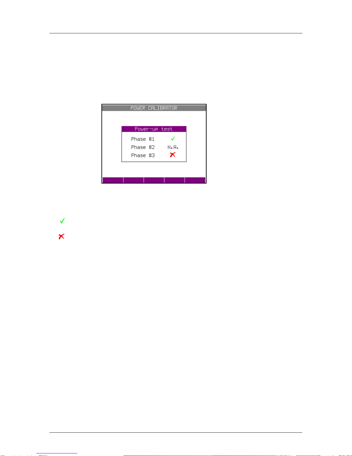
2.2 Power-on..............................................................................................................................7
2.3 Warm-up time.....................................................................................................................8
2.4 Replacement of fuse............................................................................................................8
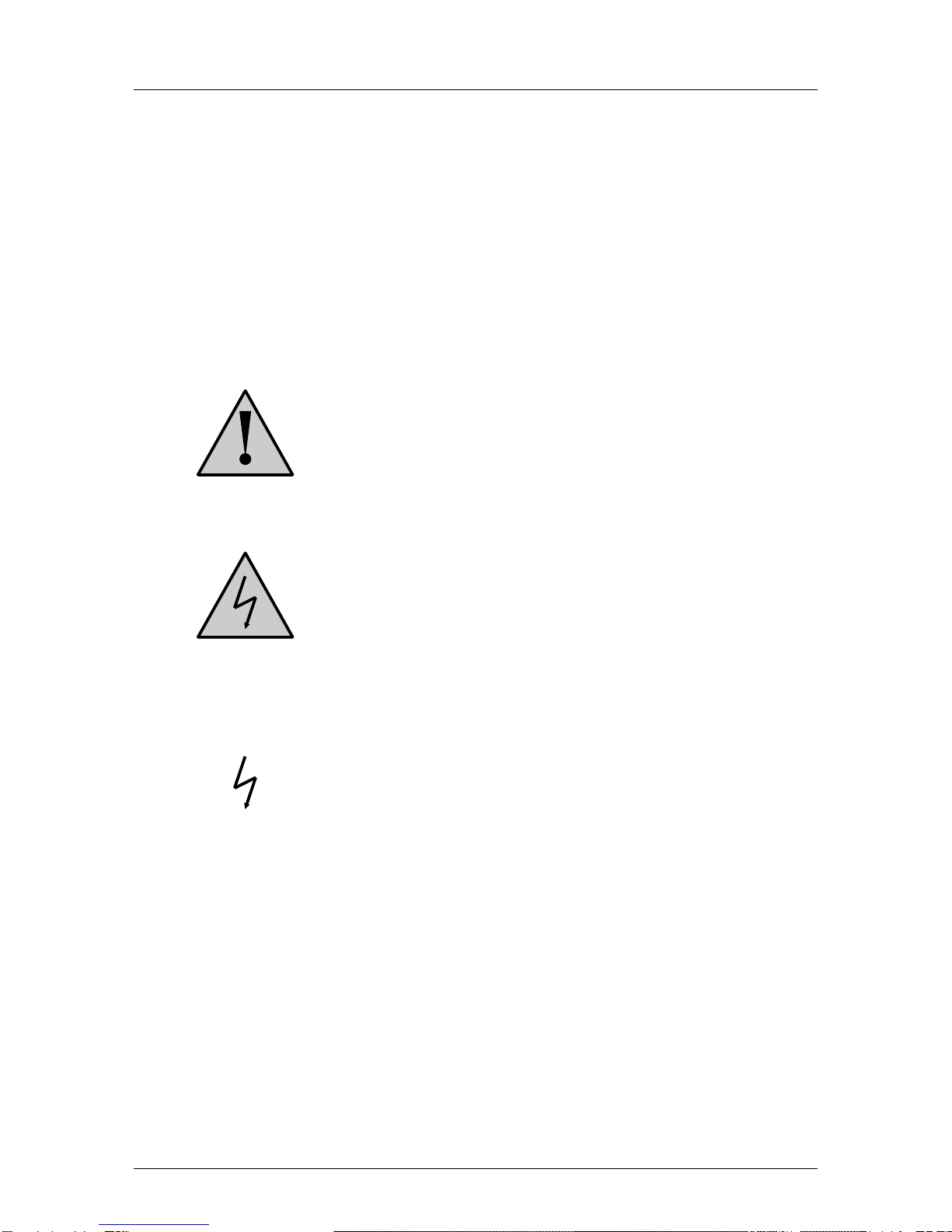
2.5 Safety precautions ..............................................................................................................9
3Description of controls.............................................................................................................10
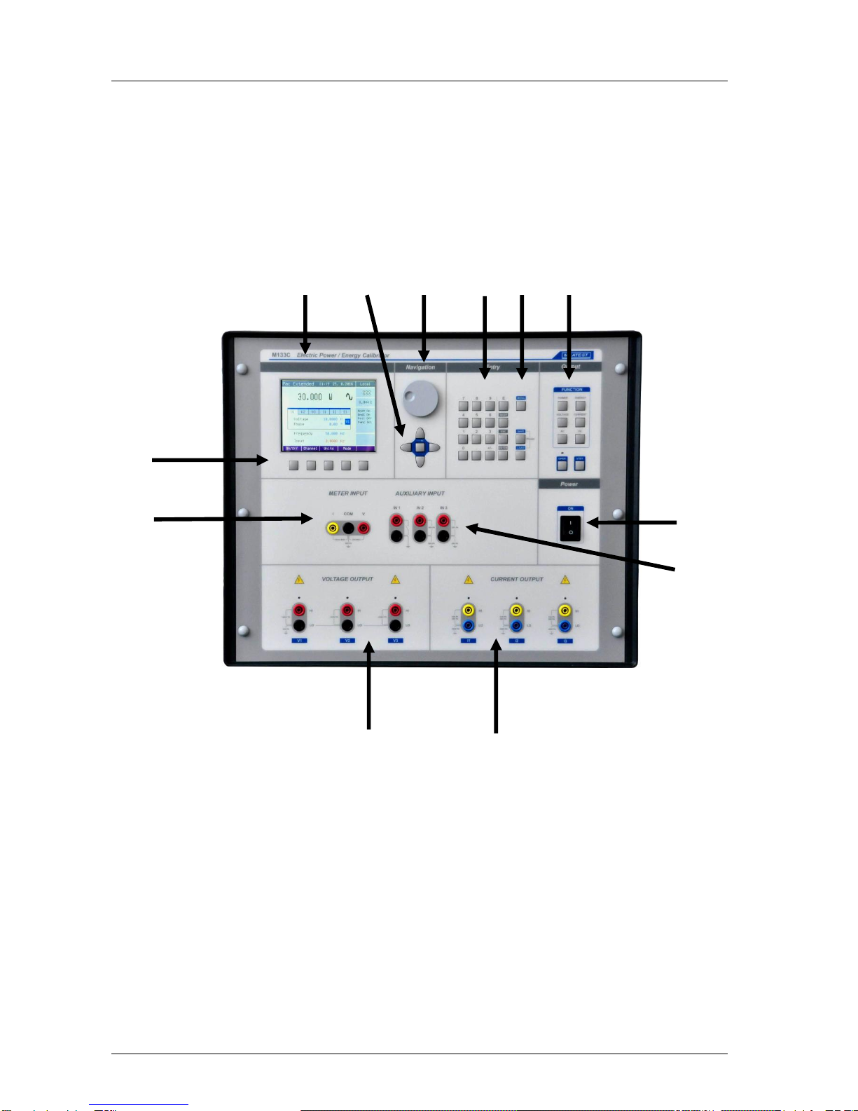
3.1 Front panel........................................................................................................................10
3.2 Rear panel.........................................................................................................................15
4Control of the calibrator ..........................................................................................................16
4.1 Selection of function.........................................................................................................16
4.2 Setting the value of output signal....................................................................................17
4.3 Connection / disconnection of output terminals............................................................18
4.4 Generation of electric power ...........................................................................................20
Setting the power in modes Pdc Basic and Pac Basic...............................................................23
Setting the power in modes Pdc High I and Pac High I (Three phase version only)................25
Setting the power in modes Pdc Extended and Pac Extended..................................................25
Setting the power in P Harmonic mode (model M133C only) .................................................27
Setting the power in P Interharmonic mode (model M133C only)...........................................29
Setting the power in P Dip/Swell mode (model M133C only).................................................31
4.5 Generation of electric energy ..........................................................................................33
Setting the energy in modes Edc Basic and Eac Basic..............................................................37
Setting the power in modes Edc High I and Eac High I (Three phase version only)................38
4.6 Generation of calibrated voltage.....................................................................................38
Setting the voltage in modes Udc Basic and Uac Basic............................................................39
4.7 Generation of calibrated current....................................................................................39
Setting the current in modes Idc Basic and Iac Basic ...............................................................41
Setting the current in modes Idc High I and Iac High I (Three phase version only).................41
5Multimeter................................................................................................................................42
5.1 Function selection.............................................................................................................42
6Calibrator setup menu (Main menu) ......................................................................................43
6.1 General Menu ...................................................................................................................43
6.2 Interface Menu .................................................................................................................44