Baylan BTM2Y User manual
4
Testing Patch cables:
“Patch” cables have both ends accessible at the same location.
Usually, these cables are less than 25ft in length, and are
not installed in a wall orceiling.Since both ends are accessible,
one end one be plugged into the 4 in 1 Main unit,and the
other into the remote unit. It is unecessary to remove the
remote unit from its docked position on the Main unit.
Testing Installed cables:
If the two ends of testing cable are not in the same location, the
Remote can be detached from the Main unit. Once detached, the
Remote can be attached to one end a cable, and the Main unit
attached to the other end of the cable.
Performing the Test:
Once the Remote and Main unit are attached to the ends of
the cable, testing may begin, simply press and release the
Test Button on the Main unit, observe the LED indicators,
and note the “beep” sound that comes from the Main unit.
Power LED:
The Power LED should light whenever the “Test” Button is
pressed and released. It will be on for a minimum of 5 seconds.
If the power LED does not light, replace the battery.
Low Battery LED:
The low Battery LED should not light . If it does, replace the
battery.
No connection LED/Single Beep:
If the Remote is not connected to the Main unit with a cable, or
the cable has no intact conductors, the No Connection LED will
light and the Beeper will sound Once.
Note: When testing an RJ-45 STP cable. The S/G must light.
When testing an RJ-45 UTP cable. The S/G LED must not light.
The 4 in 1 is intended to test complete cables. It may not find
faults in cables that are intentionally incomplete. For example,
the standard EIA/TIA 568 RJ-45 terminated Ethernet cable is
expected to contain 8 conductors. If only 4 conductors are used
between the RJ-45 connectors, the 4 in 1 may not properly
identify the faults.
Interpreting the Results:
5
RJ-11/12 cables may have
2 connection cables, LED 3 and 4 must light.
4 connection cables, LED 2, 3, 4 and 5 must light.
6 connection cables, LED 1, 2, 3, 4, 5 and 6 must light.
The Numbered LEDs don’t indicate that a GOOD connection
exists, only that a connection exists. If the Short or Cross LEDs
are Lit, there is a fault in the cable.
Connected LED/ 3Beepers/ Short LED/ Numbered LEDs
If the Connected LED lights, the Beeper emits 3 beeps, and the
Short LED lights, the cable has a fault. The Numbered LEDs
indicate the location of a short.
Note: In the Short mode, the Numbered LEDs only indicated the
location of the shorts. The other connections in the cable are not
indicated. If more than 3 numbered LEDs light, there may be
multiple shorts in the cable.
Connected LED/ 2 Beepers/ Cross LED/ Numbered LEDs
If the Connected LED lights, the Beeper emits 2 beeps, and the
Cross LED lights, the cable has a fault.
Notes: In the Cross-mode, the Number LEDs indicate
connections but do not indicate the location of the cross.
RJ-11 cables used for telephone connections are often
crossed. Even new cables are often crossed. This seldom
affects the performance of standard analog telephone lines
(POTS). Digital telephone lines and old touch-tone phones
may be polarity sensitive, so a crossed cable may prevent
them from working properly.
Maintenance:
4 in 1 Cable Tester is a precision test instrument and, when
used as described in this manual, should not require
maintenance. There are no internal adjustments. Calibration is
not required.
To clean outside of the tester, use a cloth dampened with a mild
detergent solution. Do not use any abrasive cleansers, or
chemical solvents that may damage the tester.
CABLE TESTER
YOUR EXCELLENT HELPER IN CABLE TEST
User’s Manual
4 IN 1
CABLE TESTER
TESTED UPTO
1500 FT.
(Do notuse until you read this manual carefully)
WWW.BAYLAN.COMPM:BM530601-0
BTM2Y
1
Introduction:
The 4 in 1 Cable Tester tests 4 common LAN and Computer
cables. It tests installed cables or patch cords with RJ-45,
RJ-11, USB, and BNC connectors. It is intended to test
cables with straight through connections not cables with
reversed or transposed connections like some LAN
crossover cables or reverse wired telephone cables.
Main Unit
Remote Unit
RJ45- BNC Adaptor
Instruction Manual
Carrying Case
Cautions:
Packing List:
WARNING
This tester is not intended for live circuits .
Attaching this tester to a powered circuit will
result in damage to the tester
or injury to the user.
Read all instructions in this manual before using this tester.
Failure may result in damage to the tester or injury to the user.
Repairs and maintenance must only be carried out by qualified
service personnel or qualified electricians/technicians who know
the dangers of, and the safety rules applicable to this type of
equipment.
Do not touch the ends of the cables when operate it. An
unexpected dangerous potential may be present.
Do not apply voltage or current to any of the testers connectors.
Do not use this tester to make measurements in adverse
environments such as rain, snow, fog, or locations with steam,
explosive gases or dusts.
Avoid usage near strong electrostatic fields (high voltage power
lines,televsions,computer monitors,etc.).
Avoid usage near strong RF fields (radio or television transmit-
ters, walkie talkies, cellular phones etc.).
Remove the battery when the tester isn’t used for more than 1
month. Chemical leakage from the battery could damage the
tester.
2
Features:
Test 4 types of cables
Simple one button test
Ergonomic portable handheld design
Tests installed wiring or patch cables
Remote unit stores in Main unit
1500 ft test distance (RJ-45/RJ-11/BNC)
Built in battery access
LEDs indicate connections and faults
Beeper provides audible annunciation of test results
Tests shielded (STP) or unshielded(UTP) LAN cables
Test shields USB cables
Cable Types Tested:
● UTP and STP LAN cables,terminated in RJ-45 male
connectors. (EIA/TIA 568)
● RJ-11 cables with male connectors, 2 to 6 conductor installed.
● USB cables with Type A flat plug on one end and type
square Plug on other end.
● BNC cables with male connectors.
Faults Indicated:
No Connection, Shorts, Opens, Crosses.
Low battery Indicator: LED lights to indicate low battery.
Case Dimensions: 7.25×4.0×1.0 inches (L×W×H).
Weight: 202 grams, 0.445Ibs.(Without battery).
Battery: 1* 9-Volt Alkaline battery.
General Information:
The 4 in 1 Cable Tester, it functions by pressing one-
single button on the panel. User can get clear test results
from the 8 light and knowing the cable is connected. No
connection, short or Non-parallel.
Note: Only one cable can be tested at a time. (eg) A BNC cable
and RJ-45 cable cannot be tested simultaneously.
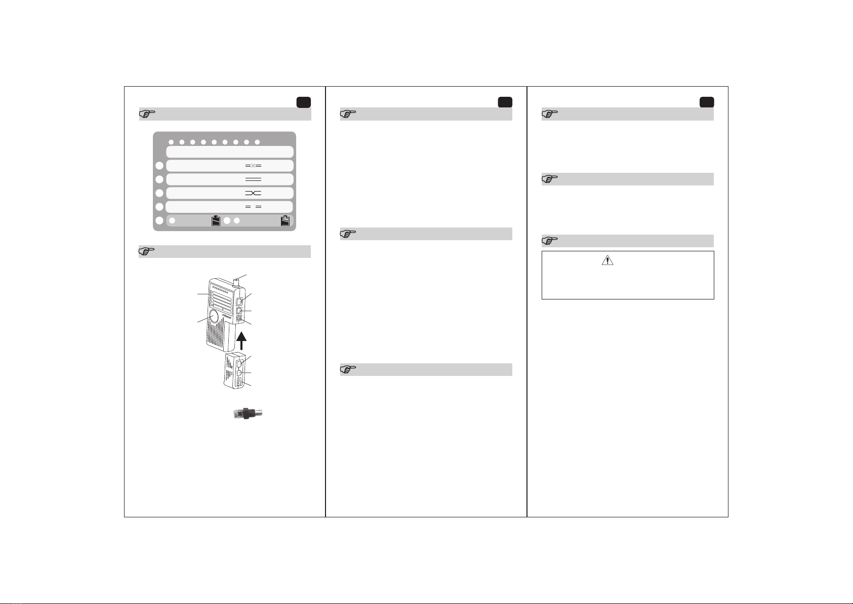
The MAIN and REMOTE unit:
The 4 in 1 Cable Tester, is consists of a Master unit and
Remote unit. The Remote is detachable when testing cables
Be careful when remove it from the master because the
plastic edge is a little sharp.
Specications:
Operation:
Panel Diagram:
RJ-45/RJ-11/USB/BNC
SHORT
PASS
CROSS
OPEN
BATTERY GOOD
BATTERY LOW
S C/1 2 3 4 5 6 7 8 Pin/Wires
Condition
3
Interfaces
RJ45- BNC Adaptor
Test Button
Display RJ-45 Jack
RJ-45 Jack
RJ-11 Jack
RJ-11 Jack
USB Jack
USB Jack
BNC Jack


