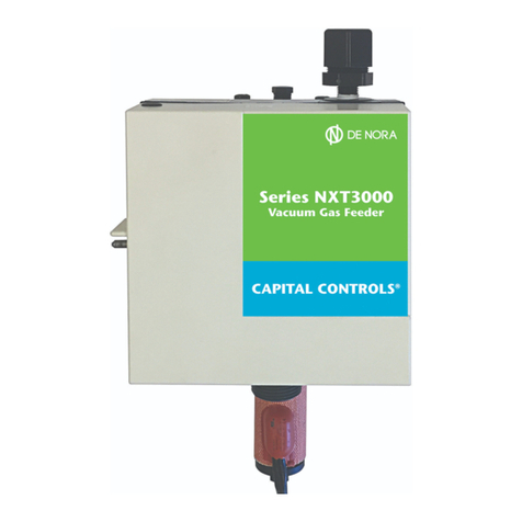
Severn Trent NXT3000 Series Training manual

- 1 - 100.6701.11
Instruction Bulletin - Series NXT3000
Cylinder, Ton Container, or Wall
Mounted Vacuum Regulator
100PPD(10kg/h)CylinderMounted500PPD(10kg/h)TonContainerMounted
WallMounted
WWW.QUANGMINHVN.COM

100.6701.11 - 2 -
These instructions describe the installation, operation and maintenance of the subject equipment. Failure to strictly follow
these instructions can lead to an equipment rupture that may cause significant property damage, severe personal injury and
even death. If you do not understand these instructions, please call Severn Trent Water Purification for clarification before
commencing any work at 215-997-4000 and ask for a Field Service Manager. Severn Trent Water Purification, Inc. reserves the
rights to make engineering refinements that may not be described herein. It is the responsibility of the installer to contact
Severn Trent Water Purification, Inc. for information that cannot be answered specifically by these instructions.
Any customer request to alter or reduce the design safeguards incorporated into Severn Trent Water Purification equip-
ment is conditioned on the customer absolving Severn Trent Water Purification from any consequences of such a deci-
sion.
Severn Trent Water Purification has developed the recommended installation, operating and maintenance procedures with
careful attention to safety. In addition to instruction/operating manuals, all instructions given on labels or attached tags should
be followed. Regardless of these efforts, it is not possible to eliminate all hazards from the equipment or foresee every
possible hazard that may occur. It is the responsibility of the installer to ensure that the recommended installation instructions
are followed. It is the responsibility of the user to ensure that the recommended operating and maintenance instructions are
followed. Severn Trent Water Purification, Inc. cannot be responsible deviations from the recommended instructions that may
result in a hazardous or unsafe condition.
Severn Trent Water Purification, Inc. cannot be responsible for the overall system design of which our equipment may be an
integral part of or any unauthorized modifications to the equipment made by any party other that Severn Trent Water Purifica-
tion, Inc.
Severn Trent Water Purification, Inc. takes all reasonable precautions in packaging the equipment to prevent shipping damage.
Carefully inspect each item and report damages immediately to the shipping agent involved for equipment shipped “F.O.B.
Colmar” or to Severn Trent Water Purification for equipment shipped “F.O.B Jobsite”. Do not install damaged equipment.
SEVERN TRENT SERVICES, COLMAR OPERATIONS
COLMAR, PENNSYLVANIA, USA
ISO 9001: 2008 CERTIFIED
WWW.QUANGMINHVN.COM

- 3 - 100.6701.11
Table of Contents
1 INTRODUCTION . . . . . . . . . . . . . . . . . . . . . . . . . . . . . . . . . . . . . . . . . . . . . . . . . . . . . . . . . . . . . . . . . . 4
1.1 General . . . . . . . . . . . . . . . . . . . . . . . . . . . . . . . . . . . . . . . . . . . . . . . . . . . . . . . . . . . . . . . . . . . . . . . . 4
1.2 Warranty . . . . . . . . . . . . . . . . . . . . . . . . . . . . . . . . . . . . . . . . . . . . . . . . . . . . . . . . . . . . . . . . . . . . . . . . 4
1.3 Standard Equipment . . . . . . . . . . . . . . . . . . . . . . . . . . . . . . . . . . . . . . . . . . . . . . . . . . . . . . . . . . . . . . . . 4
1.4 Specifications . . . . . . . . . . . . . . . . . . . . . . . . . . . . . . . . . . . . . . . . . . . . . . . . . . . . . . . . . . . . . . . . . . . . 5
2 OPERATION . . . . . . . . . . . . . . . . . . . . . . . . . . . . . . . . . . . . . . . . . . . . . . . . . . . . . . . . . . . . . . . . . . . . . 6
2.1 General . . . . . . . . . . . . . . . . . . . . . . . . . . . . . . . . . . . . . . . . . . . . . . . . . . . . . . . . . . . . . . . . . . . . . . . . 6
2.2 Safety Features . . . . . . . . . . . . . . . . . . . . . . . . . . . . . . . . . . . . . . . . . . . . . . . . . . . . . . . . . . . . . . . . . . . 6
2.3 Principles of Operation . . . . . . . . . . . . . . . . . . . . . . . . . . . . . . . . . . . . . . . . . . . . . . . . . . . . . . . . . . . . . 7
2.4 Capacity . . . . . . . . . . . . . . . . . . . . . . . . . . . . . . . . . . . . . . . . . . . . . . . . . . . . . . . . . . . . . . . . . . . . . . . . 7
2.5 Typical Gas Feed Systems . . . . . . . . . . . . . . . . . . . . . . . . . . . . . . . . . . . . . . . . . . . . . . . . . . . . . . . . . . . 7
3 INSTALLATION . . . . . . . . . . . . . . . . . . . . . . . . . . . . . . . . . . . . . . . . . . . . . . . . . . . . . . . . . . . . . . . . . . . 9
4 OPERATING INSTRUCTIONS . . . . . . . . . . . . . . . . . . . . . . . . . . . . . . . . . . . . . . . . . . . . . . . . . . . . . . . . 19
4.1 Initial Start-Up . . . . . . . . . . . . . . . . . . . . . . . . . . . . . . . . . . . . . . . . . . . . . . . . . . . . . . . . . . . . . . . . . . . 19
4.2 Operation . . . . . . . . . . . . . . . . . . . . . . . . . . . . . . . . . . . . . . . . . . . . . . . . . . . . . . . . . . . . . . . . . . . . . . 23
5 SHUTDOWN . . . . . . . . . . . . . . . . . . . . . . . . . . . . . . . . . . . . . . . . . . . . . . . . . . . . . . . . . . . . . . . . . . . . 28
5.0 Shutdown for Servicing . . . . . . . . . . . . . . . . . . . . . . . . . . . . . . . . . . . . . . . . . . . . . . . . . . . . . . . . . . . . 28
5.1 Shutdown for Extended Period . . . . . . . . . . . . . . . . . . . . . . . . . . . . . . . . . . . . . . . . . . . . . . . . . . . . . . . 28
6 SERVICE . . . . . . . . . . . . . . . . . . . . . . . . . . . . . . . . . . . . . . . . . . . . . . . . . . . . . . . . . . . . . . . . . . . . . . 29
6.1 General . . . . . . . . . . . . . . . . . . . . . . . . . . . . . . . . . . . . . . . . . . . . . . . . . . . . . . . . . . . . . . . . . . . . . . . 29
6.2 Cleaning Agents . . . . . . . . . . . . . . . . . . . . . . . . . . . . . . . . . . . . . . . . . . . . . . . . . . . . . . . . . . . . . . . . . . 30
6.3 Lubricating Agents . . . . . . . . . . . . . . . . . . . . . . . . . . . . . . . . . . . . . . . . . . . . . . . . . . . . . . . . . . . . . . . . 30
6.4 O-Ring . . . . . . . . . . . . . . . . . . . . . . . . . . . . . . . . . . . . . . . . . . . . . . . . . . . . . . . . . . . . . . . . . . . . . . . 30
6.5 Diaphragms . . . . . . . . . . . . . . . . . . . . . . . . . . . . . . . . . . . . . . . . . . . . . . . . . . . . . . . . . . . . . . . . . . . . 30
6.6 Check Valves . . . . . . . . . . . . . . . . . . . . . . . . . . . . . . . . . . . . . . . . . . . . . . . . . . . . . . . . . . . . . . . . . . . 30
6.7 Hose Lines . . . . . . . . . . . . . . . . . . . . . . . . . . . . . . . . . . . . . . . . . . . . . . . . . . . . . . . . . . . . . . . . . . . . . 30
6.8 Tubing Replacement . . . . . . . . . . . . . . . . . . . . . . . . . . . . . . . . . . . . . . . . . . . . . . . . . . . . . . . . . . . . . . . 30
6.9 Inlet Valve . . . . . . . . . . . . . . . . . . . . . . . . . . . . . . . . . . . . . . . . . . . . . . . . . . . . . . . . . . . . . . . . . . . . . . 30
6.10 Manifold . . . . . . . . . . . . . . . . . . . . . . . . . . . . . . . . . . . . . . . . . . . . . . . . . . . . . . . . . . . . . . . . . . . . . . . 30
7 TROUBLESHOOTING CHART . . . . . . . . . . . . . . . . . . . . . . . . . . . . . . . . . . . . . . . . . . . . . . . . . . . . . . . . 31
8 APPENDIX . . . . . . . . . . . . . . . . . . . . . . . . . . . . . . . . . . . . . . . . . . . . . . . . . . . . . . . . . . . . . . . . . . . . . 34
Vacuum Lines - Limits of Extension . . . . . . . . . . . . . . . . . . . . . . . . . . . . . . . . . . . . . . . . . . . . . . . . . . . . . . . . . 35
Figure 11 Pictorial Representation of the Reference Distances Plotted in Figure 12 through 14. . . . . . . . . . . . . 35
Figure 12 Vacuum Line(s) Limits of Extension vs. Maximum System Capacity for Chlorine Gas
Dispensing System . . . . . . . . . . . . . . . . . . . . . . . . . . . . . . . . . . . . . . . . . . . . . . . . . . . . . . . . . . . 37
Figure 13 Vacuum Line(s) Limits of Extension vs. Maximum System Capacity for Sulfur Dioxide
Dispensing System . . . . . . . . . . . . . . . . . . . . . . . . . . . . . . . . . . . . . . . . . . . . . . . . . . . . . . . . . . . 38
Figure 14 Vacuum Line(s) Limits of Extension vs. Maximum System Capacity for Ammonia
Dispensing System . . . . . . . . . . . . . . . . . . . . . . . . . . . . . . . . . . . . . . . . . . . . . . . . . . . . . . . . . . . 39
FIGURES
1 Basic System Schematics . . . . . . . . . . . . . . . . . . . . . . . . . . . . . . . . . . . . . . . . . . . . . . . . . . . . . . . . . . . 8
2 Cylinder Mounted Vacuum Regulators . . . . . . . . . . . . . . . . . . . . . . . . . . . . . . . . . . . . . . . . . . . . . . . . . . 10
3 Ton Container and Wall Mounted Vacuum Regulators . . . . . . . . . . . . . . . . . . . . . . . . . . . . . . . . . . . . . . . . 11
4 Mounting Cylinder Mounted Vacuum Regulators. . . . . . . . . . . . . . . . . . . . . . . . . . . . . . . . . . . . . . . . . . . . 12
5 Mounting Ton Container Mounted Vacuum Regulators . . . . . . . . . . . . . . . . . . . . . . . . . . . . . . . . . . . . . . . 12
6 Mounting Wall Mounted Vacuum Regulators . . . . . . . . . . . . . . . . . . . . . . . . . . . . . . . . . . . . . . . . . . . . . . 13
7 Connections - Wall Mounted Vacuum Regulators . . . . . . . . . . . . . . . . . . . . . . . . . . . . . . . . . . . . . . . . . . . 14
8 Out-of-Gas Alarm Switch . . . . . . . . . . . . . . . . . . . . . . . . . . . . . . . . . . . . . . . . . . . . . . . . . . . . . . . . . . . . 15
9SO
2Cylinder Adaptor Plate . . . . . . . . . . . . . . . . . . . . . . . . . . . . . . . . . . . . . . . . . . . . . . . . . . . . . . . . . 15
10 Wall Mounted Vacuum Switches . . . . . . . . . . . . . . . . . . . . . . . . . . . . . . . . . . . . . . . . . . . . . . . . . . . . . . 16
11 Vacuum Regulator Exploded View . . . . . . . . . . . . . . . . . . . . . . . . . . . . . . . . . . . . . . . . . . . . . . . . . . . . . 17
12 Meter Exploded View . . . . . . . . . . . . . . . . . . . . . . . . . . . . . . . . . . . . . . . . . . . . . . . . . . . . . . . . . . . . . . 18
WWW.QUANGMINHVN.COM

100.6701.11 - 4 -
1 INTRODUCTION
1.1 General
The vacuum regulators are engineered and carefully tested to assure years of satisfactory operation. Correct
installation and proper care will ensure continued trouble free operation. Read instructions carefully and save for
future reference.
This instruction manual covers the
NXT3000
Series vacuum regulator and it's function within a gas feed system.
The complete gas feed system consists of a vacuum regulator, a gas meter assembly with a manual or automatic
rate valve and an ejector. Refer to the following instruction manuals for other system components:
Meter Assemblies 100.6702
Ejectors 122.6001, 122.6006, 122.6010, 122.6060
Also, the following literature is referenced throughout:
Changing Gas Cylinders Instruction Card 24563.1
Vacuum Line Size Requirements 100.4601
Chemical feed equipment technical information 010.3650
1.2 Warranty
See Bulletin 005.9001 for Severn Trent Services equipment warranty.
NOTE: The
NXT3000
vacuum regulator is designed for use in systems where the feed rate is manually or
automatically set and operation is either continuous or start/stop. The Severn Trent Services equipment warranty
and service policy is null and void, as it pertains to user protection, if the
NXT3000
Series vacuum regulator is
misapplied.
1.3 Standard Equipment
The
NXT3000
Series gas feeder system consists of the following major components and accessories:
1.3.1 Vacuum regulator, which connects to the gas container valve or a gas manifold.
1.3.2 Ejector assembly. See Instruction Manuals 122.6001, 122.6006, 122.6010, 122.6060.
1.3.3 Metering or multiple feed points, separate meter assemblies. See Instruction Manual 100.6702.
1.3.4 Accessories
a. (1) - chlorine cylinder/container valve wrench.
b. (1) - O-ring lube
c. (1) - Poly leak detector squirt bottle
d. (6) - Inlet valve filter pads
e. (1) - Vent tubing insect screen
f. (4) - Lead valve gaskets
g. (1) - 1/2" NPT to 5/8" tubing elbow
h. 25 FT - 5/8" tubing
i. (2) - 1/2" NPT x 3/8" tubing connector
j. (1) - 1/4" NPT x 1/2" tubing connector
k. (1) - Bushing, 1/2" MNPT x 1/4" FNPT
WWW.QUANGMINHVN.COM

- 5 - 100.6701.11
NOTE: This instruction manual covers the vacuum regulator only. Since the vacuum regulator is one part
of a gas feed system, references will be made within this bulletin to meter assemblies, ejectors and
other ancillary equipment that complete the various systems. Installation of a complete system
is covered within.
1.4 Specifications
Capacity: Chlorine - 1 to 500 PPD (20 g/h to 6 g/h)
Sulfur Dioxide - 1 to 500 PPD (20g/h to 10 g/h)
Ammonia - 5 to 250 PPD (30 g/h to 5 g/h)
Carbon Dioxide - 0.75 to 375 PPD (15 g/h to 7 kg/h)
The maximum delivery capacity is dependent upon the mounting location of the vacuum regulator and the
ambient temperature. These capacities are listed in Table A for an ambient temperature of 70°F
to 5°F.
deldnaHgnieBsaG
noitacoLgnitnuoMrotalugeRmuucaV
llaWreniatnoCnoTrednilyC
edixoiDrufluSroenirolhC d/bl005
h/g
k01
d/bl005
h/gk01
d/bl001
h/gk2
ainommA d/bl052
h/gk5 ANAN
*edixoiDnobraC d/bl573
h/gk7 ANAN
*Due to the high gas pressure in the carbon dioxide storage cylinders, a two stage pressure regulator is
required between the gas source and the vacuum regulator.
Temperature limits: 35° to 130°F (2° to 54°C)
Maximum inlet pressure: 300 PSIG
Manifold heater power: 25 Watt, 120 or 240 VAC, 50/60 Hz
WWW.QUANGMINHVN.COM

100.6701.11 - 6 -
2 OPERATION
2.1 General
A. Vacuum Regulator
The vacuum regulator serves to reduce the supply pressure in a gas cylinder or ton container to a regulated
vacuum for safe transport of the gas to the point of application. A leak in any portion of the vacuum transport
line simply allows air to be pulled into the system. A substantial vacuum line break will stop gas feed from
taking place. The vacuum regulator is a spring opposed diaphragm type that resumes vacuum to operate the
gas inlet valve. The vacuum regulator can control gas flow rates from 1 to 500PPD without any component
changes.
For manually controlled systems, the flow rate of gas through the regulator is set and indicated by a meter
assembly which contains a manually adjusted needle valve, called a rate valve. One or more meter
assemblies may be furnished with each vacuum regulator and they may be either integrally mounted on the
vacuum regulator or wall mounted, as required. The operating vacuum that pulls the gas through the system
is created by a separately mounted ejector, one normally being required for each meter assembly.
Each vacuum regulator is equipped with a vacuum actuated, manually reset, three position, “status” lever
marked RESERVE, OPERATING, and EMPTY. When a system is placed into operation, the lever is manually set
to the operating position. When the gas in the cylinder or ton container is exhausted, or has been
inadvertently interrupted, the lever automatically moves to the EMPTY position. The RESERVE position is used
when a dual regulator type gas dispensing system is furnished, The RESERVE position indicates that the gas
cylinder is full and is in stand-by condition. When the operating tank is exhausted, its status lever moves to
EMPTY and the reserve tank status lever moves to the OPERATING position. This provides an automatic
changeover of gas feed from the exhausted to the full gas supply container.
B. Meter-Rate Valve Assembly
The meter assembly is a variable area type meter and provides visual indication of the gas flow rate set by
the rate valve.
The rate valve is located at the meter outlet (top) to provide manual selection of the desired gas flow rate.
The capacity range of each meter-rate valve assembly is clearly indicated by a calibrated scale, direct
reading in pounds per day (lb/d) and grams per hour (g/h) or kilograms per hour (kg/h), etched on the
meter assembly tube.
For systems requiring automatic feed control, an automatic valve is provided to be piped between the
ejector and the meter assembly. The manual valve on the meter assembly is not supplied for this mode of
operation.
C. Ejector
The ejector, operated by the flow of water or process liquid under sufficient pressure and velocity, creates
the necessary vacuum to operate the regulator. In some instances, a booster pump is required to provide
sufficient water pressure and flow rate.
2.2 Safety Features
The gas inlet valve of the vacuum regulator provides positive shut-off in the absence of operating vacuum.
Therefore, the regulator is sealed off from the gas supply if a major leak should develop in the vacuum portion of
the gas dispensing system during normal operation or at shutdown when the water supply to the ejector is shut off.
This valve is protected by a mesh type filter located within the gas inlet connection.
A pressure relief valve, within the vacuum regulator, provides for venting gas, through a vent connection, to a
remote and suitable location should gas at greater than atmospheric pressure enter the regulator. This abnormal
condition could occur as liquid chemical enters the regulator; or, the gas inlet valve of the regulator does not
close tightly due to the accumulation of foreign matter not removed by the filter.
WWW.QUANGMINHVN.COM

- 7 - 100.6701.11
The manifold assembly, supplied with wall and ton container mounted regulators, has a liquid chemical trap, an
wrap-around type heater and a cartridge type filter. The trap catches any condensed gas vapors (liquid chemical)
which may form in the gas supply line of a wall mounted unit or the small volume of liquid chemical discharged
through the gas valve of a ton container each time a new container is placed in service to prevent its entrance
into the regulator. The heater vaporizes any liquid chemical and prevents any gas from condensing in the
manifold, thereby permitting only gas to enter the regulator. The filter cartridge serves to remove entrained
foreign particles from the gas entering the manifold assembly, thereby reducing the solids loading on the mesh
type filter located in the gas inlet connection of the regulator.
2.3 Principle of Operation
When the ejector is operating, gas enters the regulator, being reduced from supply pressure to a constantly
regulated vacuum by the throttling action of the regulator, the meter assembly rate valve assembly and into the
ejector. Within the ejector, the gas is thoroughly mixed with the water or process liquid to form a chemical
solution which is delivered via solution hose or piping to the point of application.
WARNING
All components of the gas dispensing system are constructed of materials
capable of withstanding the corrosive action of the particular gas for which
the system has been specified. Never attempt to use any component
for handling a gas different from that for which it has been purchased.
Failure to observe this warning can result in equipment failure and bodily injury.
2.4 Capacity
Each vacuum regulator has the maximum feeding capacity of 500PPD of chlorine. The actual system maximum is
determined by the flowmeter-rate valve combination and the commensurate ejector sizing. The capacity of an
installed system may be changed by changing the meter assembly and/or ejector capacity components. Refer to
the meter assembly parts list, 100.7602 and ejector parts lists, Section 122 for the specific part numbers
associated with each ejector.
2.5 Typical Gas Feed Systems
Figure 1 illustrates several basic system arrangements. The meter-rate valve assembly may be mounted directly
on the vacuum regulator or remotely on a wall. The meter assemblies have the ability of being ganged with the
actual total gas flowrate limited by the 500PPD capacity of the vacuum regulator for up to five separate feed
points. A mix of automatic and manual feed points are also possible as the gas feed processes dictate.
Automatic switchover may be achieved by adding a second vacuum regulator and connecting the outlets to a tee
connected to the meter assemblies and following the procedures outlined further in this manual.
WWW.QUANGMINHVN.COM

100.6701.11 - 8 -
Figure 1 - Basic System Schematics
WWW.QUANGMINHVN.COM

- 9 - 100.6701.11
3 INSTALLATION
Select a location which can be isolated from unauthorized personnel. Outdoor installations for cylinder or ton
container mounted regulators are permissible provided that the ambient temperature will not fall below 35°F (2°C)
for chlorine and ammonia systems; or, 40°F (5°C) for sulfur dioxide systems. Outdoor installations for wall
mounted regulators are not recommended (especially if the gas supply system consists of two or more containers)
since a sudden decrease in ambient temperature will result in the formation of condensed gas vapors (liquid
chemical) in the gas supply line. This liquid will be swept into the manifold and if sufficient in volume to exceed the
vaporizing capacity of the manifold heater, will flood the manifold and enter the regulator.
CAUTION
The corrosion resistant plastics used in the construction of all
regulators and meter-rate valve assemblies, regardless of the particular
gas service for which they have been supplied, will soften and distort
above 130°F (54°C). Therefore, the ambient temperature, in every instance,
must never exceed this maximum allowable limit.
For outdoor installations, select an area which will provide natural protection for the gas supply against direct
sunlight. If this is not possible, erect an open type structure to provide this protection. Observe the upper and lower
temperature limits.
For indoor installations, select a well ventilated enclosure provided with a source of heat, if necessary, to maintain,
a comfortable ambient temperature. Additionally, the enclosure should be of sufficient size to permit easy access
for inspection and maintenance of the regulator and gas supply. And finally, to provide for maximum safety of
operating personnel, the enclosure should be equipped and fitted as described under the Personnel Safety Section of
Instruction Bulletin 010.3550.
The relative locations of the regulator(s); the remote mounted meter-rate valve assemblies, if used; and the ejector(s)
must be chosen so that the length(s) of the vacuum line(s) does not exceed the value(s) shown in the appendix.
Maximum gas flow to the point(s) of application will not be achieved if these limits are exceeded. Therefore, it will
be necessary to refer to the appendix before locating the components of the system to verify that the length of each
interconnecting vacuum line (and vent line) when the regulator is mounted on a cylinder valve or the gas valve of a ton
container to permit easy transfer of the regulator from one cylinder or container to another. Arrange all vacuum lines
to prevent crimping.
The vent line(s), one required for each regulator, must be extended to a suitable area (outside the building for indoor
installations) where gas fumes cannot cause damage or endanger personnel. Although there is no restriction (within
practical limits) to the distance over which the vent line(s) can be extended, each line, if applicable, must be run
individually. Multiple vent lines cannot be manifolded. The vent line must slope downward from the vacuum regulator
to provide a positive drain, preventing accumulation of any moisture in the vent line. The end of the vent line(s) must
be turned downward to prevent the entrance of water. The fine mesh plastic screen(s) (supplied in the accessory
package) must be installed over the outlet(s) to prevent insects from entering the line(s).
When extending vent lines, eliminate low spots to prevent trapping condensed water vapor and arrange to prevent
crimping.
All threaded plastic-to-plastic pipe joints must be lubricated to prevent galling of the threads, provide a perfect seal
and to permit ease of disassembly. The recommended lubricating agent is Teflon (self lubricating) tape. Apply tape
to the male pipe threads, one thread from the end, only to prevent it from entering the piping. Exercise care not to
overtighten the joints as this may crack the plastic. Slightly more than hand tight is usually sufficient.
The vacuum regulator can be direct mounted to a 150 lb cylinder, ton, container wall mounted or mounted on a multi-
container manifold.
Cylinder Mounting refer to Figure 4.
Ton Container Mounting refer to Figure 5.
Wall Mounting refer to Figure 6.
WWW.QUANGMINHVN.COM

100.6701.11 - 10 -
Figure 2 - Cylinder Mounted Vacuum Regulators
WWW.QUANGMINHVN.COM

- 11 - 100.6701.11
Figure 3 - Ton Container and Wall Mounted Vacuum Regulators
WITHINTEGRALLYMOUNTEDMETERRATEVALVEASSEMBLY WITHOUTINTEGRALLYMOUNTEDMETER RATEVALVEASSEMBLY
WWW.QUANGMINHVN.COM

100.6701.11 - 12 -
Figure 4 - Mounting Cylinder Mounted Vacuum Regulators
Figure 5 - Mounting - Ton Container Mounted Vacuum Regulators
NOTE:
Ideally, a second full RESERVE cylinder should be positioned and
secured close to the OPERATING cylinder. This will permit ease of
transfer of the regulator to the RESERVE cylinder when the
OPERATING cylinder becomes exhausted. If space limitations
prevent this, install an ordinary coat hook (of suitable size) on a
nearby wall. Then, when changing cylinders, hang the regulators
on the wall by slipping its yoke over the hook.
PROCEDURE FOR MOUNTING:
1. Place the cylinder in an upright position and secure
by chaining or tying to a solid support to keep it
from tipping or falling.
2. Remove the valve protective hood.
3. Remove the cap from the cylinder valve.
4. Loosen the yoke screw and move the slide bar to its
full open position.
5. Install a new lead gasket in the inlet fitting of the
regulator.
WARNING
Remove any used lead gaskets; only one
gasket should be used at a time. DO NOT
REUSE GASKETS. Gas is under pressure
at this point and leaks could result in
bodily injury.
6. Slip the yoke over the cylinder valve, seat the
cylinder valve outlet in the inlet fitting and tighten the
yoke screw securely using a wrench, but do not
overtighten.
7. Check for leaks and retighten the connection as
necessary or replace with a fresh washer.
PROCEDURE FOR MOUNTING
1. Remove the protective hood to expose the valves.
2. Position the ton container so that the valves are in
a vertical position, one above the other, and chock
or cradle to prevent it from rolling.
WARNING
In the mounting position described in step 2,
the upper valve will discharge gas and is the
connection to be used for the gas dispensing system.
The lower valve (if opened) will
discharge liquid chemical and could result
in bodily injury.
3. Remove the cap from the upper (gas) valve.
4. Loosen the yoke screw and move the slide bar to
its full open position.
5. Install a new lead gasket in the adaptor fitting in the
manifold.
WARNING
Remove any used lead gaskets; only one gasket should
be used at a time. Gas is under pressure at this point
and leaks could result in bodily injury.
6. Slip the yoke over the gas valve, seat the gas
valve outlet in the adaptor inlet and tighten the yoke
screw securely using a wrench, but do not
overtighten
7. Check from leaks and retighten the connection as
necessary or replace with a fresh washer.
NOTES:
1. If the gas valve outlet faces opposite to the direction illustrated,
reverse the positions of the mounting yoke, adaptor fitting and
plug. Reseal the threads of the adaptor and plug using teflon tape.
2. Ideally, a second full RESERVE ton container should be positioned
and secured close to the OPERATING ton container. This will
permit ease of transfer of the regulator to the RESERVE container
when the OPERATING container becomes exhausted. If space
limitations prevent this, install an ordinary coat hook (of suitable
size) on a nearby wall. Then, when changing containers, hang the
regulator on a nearby wall by slipping its yoke over the hook.
WWW.QUANGMINHVN.COM

- 13 - 100.6701.11
Figure 6 - Mounting - Wall Mounted Vacuum Regulators
GENERAL
One of the gas inlet connection is fitted with a plug. The
plug can be removed and installed in the opposite side if it is
not convenient (when mounting on a wall) or possible
(when mounting on the gas valve of a ton container) to use
the open connection as supplied. If the plug is relocated,
reseal the threads using teflon tape.
1. Mount vertically plumb on a wall (or other suitable
surface) at a convenient height for setting the rate valve
and reading the flowmeter if integrally mounted.
2. Provide four threaded openings to accept 1/4 - 20 hex
head cap screws. Slip a washer over each screw and
install the screws through the 5/16" wide mounting
slots in the manifold.
3. Connect the gas supply to the manifold as illustrated
and described in Figure 7.
WWW.QUANGMINHVN.COM

100.6701.11 - 14 -
Figure 7 -Connections - Wall Mounted Vacuum Regulators
NOTE:
USE ONLY APPROVED TYPE FLEXIBLE CONNEC-
TORS AND ADAPTOR FITTINGS, AS REQUIRED, IN
THE CONSTRUCTION AND INTERCONNECTION OF
ALL FLEXIBLE PIPE RUN PORTIONS OF THE GAS
SUPPLY SYSTEM
1. The manifold is provided with an appropriate adaptor
fitting for the intended gas service.
2. A second adaptor fitting may be added only in those
instances where the gas supply system consists of
two supply containers. It is installed (and sealed) in the
alternate (normally plugged) gas inlet connection of the
manifold. If isolation of the flexible connectors is
desired, an isolating valve may be inserted into each of
the manifold gas inlet ports in lieu of the manifold-to
-flexible connector adaptors.
PROCEDURE FOR CONNECTION TO THE GAS SUPPLYSYSTEM
For three or more container systems the manifold is
installed (and sealed) in the outlet connection of a
header, which serves to complete the interconnections
to the multiple supply containers.
3. Install the gas supply system (and complete the
inter-connection between the system and the gas inlet)
only after becoming thoroughly familiar with the information
provided in Instruction Bulletin 010.3650 concerning gas
supply containers, gas supply lines and interconnection
practices. The gas supply header, if required, must be
constructed of Schedule 80 3/4" seamless steel pipe with
3000 lb forged steel fittings.
Flexible connectors must be arranged in a smooth spiral to prevent kinking. Kinks cause mechanical damage which will result in immediate
or eventual rupture. Connectors so damaged, either during shipment, handling or at time of installation must never be used.
Cylinders must be placed in an upright position (with the valve at top) and secured by chaining or tying to a solid support to keep them from
tipping or falling.
Ton containers must be positioned so that their valves are in a vertical position, one above the other, and chocked or cradled to prevent
them from rolling. In this position, the upper valve will discharge gas; the lower valve will discharge liquid chemical. Therefore, be absolutely
certain to connect to the upper (gas) valve.
CAUTION
Each flexible connector should be arranged in a smooth curving slope (avoiding traps) and pitched back toward the container(s). This
arrangement will permit condensed gas vapors (liquid chemical) that may form in the connector(s), or gas supply header, if present, to flow
back into the container(s).
WARNING
Failure to observe these warnings can result in bodily injury.
WWW.QUANGMINHVN.COM

- 15 - 100.6701.11
Figure 8 - Out-of-Gas Alarm Switch
Figure 9 - SO2Cylinder Adaptor Plate
An optional, field mountable, switch is available for remote indication of a loss of gas supply. The switch may be
attached directly to the vacuum regulator body without disassembling the body. Refer to Instruction Bulletin100.6703
and parts list 100.7603 for further details. The kit P/N is 674B093U02
SCREW SCREW
ADAPTOR PLATE
STUD
STUD
GASKET
GASKET
GASKET
REGULATOR
VACUUM
VALVE
CYLINDER
CYLINDER
WWW.QUANGMINHVN.COM

100.6701.11 - 16 -
Accessories:
Manifold Adaptor Kits: Manifold adaptor kits are available to convert the cylinder mounted vacuum regulator to either ton
container or wall mounting.
Wall mounting kit P/N 19558
Ton container mounting kit P/N 19560
Refer to parts list 100.7606 for detailed parts listing.
Wall Mounted Vacuum Switches
Wall mounted Nema 4X vacuum switches are available for remote indication of out of spec vacuum conditions.
Low vacuum only (loss of ejector operation, break in vacuum line), P/N 806L051U02.
High vacuum only (out of gas, gas source valve closed), P/N 806L051U06.
Both high and low vacuum switches, P/N 806L051U03.
Note: Low vacuum is measured at the vacuum line coming from the ejector and high vacuum is measured at the vacuum line
between the vacuum regulator and the meter assembly.
SafeTC Container Valve Shut-off System
An automatic emergency cylinder valve shut-off system is available. Refer to specification sheet 140.0005 for more details.
Figure 10 - Wall Mounted Vacuum Switches
WWW.QUANGMINHVN.COM

- 17 - 100.6701.11
Figure 11 - Vacuum Regulator Exploded View
WWW.QUANGMINHVN.COM

100.6701.11 - 18 -
Figure 12 - Meter Exploded View
WWW.QUANGMINHVN.COM

- 19 - 100.6701.11
4 OPERATING INSTRUCTIONS
4.1 Initial Start-Up
Prior to start-up after an extended shutdown, inspect all lines and connections, making replacements as neces-
sary. If lines are transparent, inspect for blockage. Disconnect any blocked line and clean by blowing down. If
lines cannot be visually inspected, disconnect the lines and blow down to make certain no blockage exists. DO
NOT PRESSURE TEST THE VACUUM LINES AS EQUIPMENT DAMAGE WILL RESULT.
A. Checking for Operating Vacuum
1. Remove the vent valve spring and flapper located on the top of the vacuum regulator.
If the gas dispensing system is of the dual regulator type, perform this action on the furthest remote
mounted regulator since one of the purposes of this procedure is to establish that the length of the
vacuum line(s) do not exceed the maximum allowable transport distance.
2. Move the “status” lever located on the side of the regulator to its OPERATING position. Be sure that
the valve on the gas container is closed during this procedure.
If the gas dispensing system is of the dual regulator type, perform this action on both regulators since
another purpose of this procedure is to establish that the connection(s) to or throughout the gas supply
system(s) have been properly made and secured.
3. Open any shut-off valves in the chemical solution line between each ejector and its point of application.
4. Open the shut-off valve in the water supply line to each ejector and start up the booster pump(s), if
used.
5. Gradually open the rate valve of each meter-rate valve assembly while observing the upward
movement of the meter assembly float. On systems with an automatic valve, manually operate the
valve while observing the meter assembly float.
The gas dispensing system is now operating on air being drawn through the vent. Sufficient ejector
operating vacuum to provide maximum operating capacity for the complete system is verified when
each meter-valve assembly can be operated simultaneously on air at approximately;
a) 50% or higher of max-scale position for chlorine and sulfur dioxide systems; and, b) 25% or higher
of max-scale position for ammonia systems.
If the meter assembly float does not rise or if the required air flow rate is not achieved in each
assembly the first time, the gas dispensing system is placed in operation, refer to Trouble “A” in the
troubleshooting chart to determine the probable cause(s) and corrective action(s) to be taken. If either
of these conditions occur on subsequent start-ups (e.g.: following an extended period of servicing
shutdown), refer to Trouble “B” in the troubleshooting chart to determine the probable cause(s) and
corrective action(s) to be taken.
6. Replace the vent valve spring and flapper, sparingly lubricate the threads (if necessary) to provide a
perfect seal. Do not apply any lubricants to the seat seal o-ring or the vent valve seat.
7. With the system dead-ended; a) the float of each meter-rate valve assembly should fall to zero, and
b) the “status” lever located on the side of the regulator(s) should move to the EMPTY position (the
closed valve shows the same response as an empty gas container).
If either of these conditions do not occur, check that the connection(s) to or throughout the gas supply
system, associated with the regulator(s) failing to exhibit the proper response, have been properly
made as described and illustrated in Figures 4,5, or 7.
If the occurrence of these conditions cannot be traced to a faulty connection, refer to Trouble "C" or
Trouble "D". Trouble "C" in the troubleshooting chart can determine other probable cause(s) and
corrective action(s) to be taken if this is placed in operation. Trouble "D" in the troubleshooting chart
can determine other probable cause(s) and corrective action(s) to be taken on subsequent start-ups
(e.g.: following an extended period or servicing shutdown).
8. When the system exhibits the requirements set forth in steps 5 and 7, shut off the water supply to the
ejector(s).
WWW.QUANGMINHVN.COM

100.6701.11 - 20 -
B. Checking for Gas Leaks
1. General
The test solution to be used in each of the following procedures is dependent upon the gas being
handled. Use a 26°Baume' (ammonium hydroxide, aqua ammonia) ammonia solution for chlorine and sulfur
dioxide systems and a 10% hydrochloric (muriatic) acid solution for ammonia systems.
NOTE: Household ammonia is not strong enough to serve as a test solution.
If the gas dispensing system is of the dual regulator type, be certain to perform the “Checking for Gas
Leaks” procedure(s), as applicable, and independently, on each of the associated gas supply systems in
question.
WARNING
During the performance of the “Checking for Gas Leaks” procedure(s),
as applicable, be certain to use plastic or rubber gloves to protect
the hands against direct contact with the test solution. Avoid
breathing fumes emitted from the test solution and the smoke formed
(as a result of the chemical reaction which occurs between the fumes
of the test solution and the gas in question) in the immediate vicinity
of a leak as it may irritate the throat.
The gas inlet valve is functional when the “status” lever located on the side of the regulator is in its EMPTY
position. The lever automatically assumes this position during the occurrence of a high vacuum condition
within the regulator. For example, when the system is dead-ended at the conclusion of the “checking for
operation vacuum” procedure; or, when the supply of gas becomes exhausted during the course of normal
operation. Therefore, it is not necessary to move the lever to its operating position prior to, or during,
the performance of the “Checking for Gas Leaks” procedure(s). In fact, it will be impossible to do so
following the “Checking for Gas Leaks” procedure, at which time the lever becomes “vacuum locked” in
its EMPTY position and will remain so until gas pressure is applied to the gas inlet connection of the
regulator; i.e., either during or at the conclusion of the performance of each of the following
procedures.
2. Cylinder Mounted Vacuum Regulators
a. Fill the plastic squirt bottle, supplied in the accessory kit, approximately 25-50% full with the
appropriate test solution and replace the cap/nozzle.
b. Momentarily, partially open the cylinder valve to pressurize the connection and close the valve
tightly. Direct the nozzle at the joint to be tested and squeeze the bottle to expose the joint to the
test solution vapors. Do not squirt any
liquid
test solution on the process piping as this will
produce corrosion damage to the piping.
c. If the connection leaks, turn on the water supply to the ejector(s) for several minutes to evacuate
the small volume of entrapped gas, then shut off. Correct the leak by tightening the yoke screw
and repeat the pressure test. If the leak persists, replace the gasket and repeat the pressure test.
d. When the connection is secured, close the cylinder valve and proceed to Section II. Operation.
CAUTION
Cylinder valves should not be opened more than one full turn.
Opening beyond this point may result in valve damage.
One full turn will permit maximum flow through the valve.
Opening the cylinder valve less than one full turn may limit
the flow and could frost the process piping.
3. Ton Container Mounted Vacuum Regulators
a. Fill the plastic squirt bottle, supplied in the accessory kit, approximately 25-50% full with the
appropriate test solution and replace the cap/nozzle.
WWW.QUANGMINHVN.COM
Other manuals for NXT3000 Series
1
Table of contents
Other Severn Trent Controllers manuals