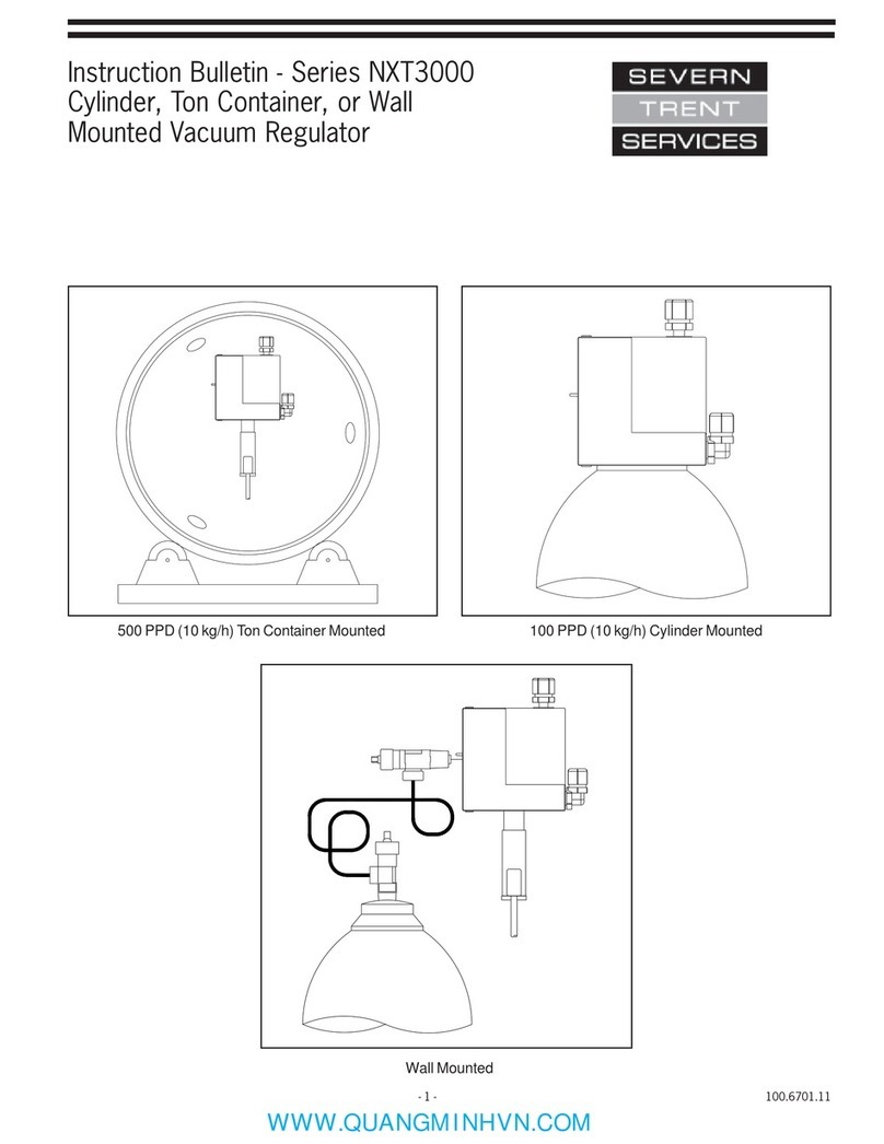
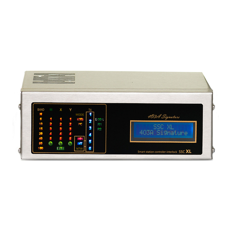
Severn Trent NXT3000 Series Training manual

- 1 - 105.6605.0
Instruction Bulletin - Series High Capacity
NXT3000 Wall Mounted Vacuum Regulator
1,000 - 3,000 PPD (30-60 Kg/h) Maximum

105.6605.0 - 2 -
Theseinstructionsdescribetheinstallation,operationandmaintenanceofthesubjectequipment. Failure to strictly follow
these instructions can lead to an equipment rupture that may cause significant property damage, severe personal injury
and even death. If you do not understand these instructions, please call Severn Trent Water Purification for clarification
before commencing any work at 215-997-4000 and ask for a Field Service Manager. Severn Trent Water Purification,
Inc. reserves the rights to make engineering refinements that may not be described herein. It is the responsibility of the
installer to contact Severn Trent Water Purification, Inc. for information that cannot be answered specifically by these
instructions.
Any customer request to alter or reduce the design safeguards incorporated into Severn Trent Water Purification
equipment is conditioned on the customer absolving Severn Trent Water Purification from any consequences
of such a decision.
Severn Trent Water Purification has developed the recommended installation, operating and maintenance procedures
with careful attention to safety. In addition to instruction/operating manuals, all instructions given on labels or attached
tags should be followed. Regardless of these efforts, it is not possible to eliminate all hazards from the equipment or
foresee every possible hazard that may occur. It is the responsibility of the installer to ensure that the recommended
installation instructions are followed. It is the responsibility of the user to ensure that the recommended operating and
maintenance instructions are followed. Severn Trent Water Purification, Inc. cannot be responsible deviations from the
recommended instructions that may result in a hazardous or unsafe condition.
Severn Trent Water Purification, Inc. cannot be responsible for the overall system design of which our equipment may
be an integral part of or any unauthorized modifications to the equipment made by any party other that Severn Trent
Water Purification, Inc.
Severn Trent Water Purification, Inc. takes all reasonable precautions in packaging the equipment to prevent shipping
damage. Carefully inspect each item and report damages immediately to the shipping agent involved for equipment
shipped “F.O.B. Colmar” or to Severn Trent Water Purification for equipment shipped “F.O.B Jobsite”. Do not install
damaged equipment.
SEVERN TRENT SERVICES, COLMAR OPERATIONS
COLMAR, PENNSYLVANIA, USA
IS ISO 9001: 2000 CERTIFIED

- 3 - 105.6605.0
Table of Contents
1 INTRODUCTION. . . . . . . . . . . . . . . . . . . . . . . . . . . . . . . . . . . . . . . . . . . . . . . . . . . . . . . . . . . . . . . . . . . . . . . . . 4
1.1 General . . . . . . . . . . . . . . . . . . . . . . . . . . . . . . . . . . . . . . . . . . . . . . . . . . . . . . . . . . . . . . . . . . . . . . . . . . . .4
1.2 Warranty. . . . . . . . . . . . . . . . . . . . . . . . . . . . . . . . . . . . . . . . . . . . . . . . . . . . . . . . . . . . . . . . . . . . . . . . . . . .4
1.3 Standard Equipment . . . . . . . . . . . . . . . . . . . . . . . . . . . . . . . . . . . . . . . . . . . . . . . . . . . . . . . . . . . . . . . . . .4
1.4 Specifications. . . . . . . . . . . . . . . . . . . . . . . . . . . . . . . . . . . . . . . . . . . . . . . . . . . . . . . . . . . . . . . . . . . . . . . .5
2 OPERATION . . . . . . . . . . . . . . . . . . . . . . . . . . . . . . . . . . . . . . . . . . . . . . . . . . . . . . . . . . . . . . . . . . . . . . . . . . . . 6
2.1 General . . . . . . . . . . . . . . . . . . . . . . . . . . . . . . . . . . . . . . . . . . . . . . . . . . . . . . . . . . . . . . . . . . . . . . . . . . . .6
2.2 Safety Features . . . . . . . . . . . . . . . . . . . . . . . . . . . . . . . . . . . . . . . . . . . . . . . . . . . . . . . . . . . . . . . . . . . . . .6
2.3 Principles of Operation. . . . . . . . . . . . . . . . . . . . . . . . . . . . . . . . . . . . . . . . . . . . . . . . . . . . . . . . . . . . . . . . .7
2.4 Capacity. . . . . . . . . . . . . . . . . . . . . . . . . . . . . . . . . . . . . . . . . . . . . . . . . . . . . . . . . . . . . . . . . . . . . . . . . . . .7
2.5 Typical Gas Feed Systems . . . . . . . . . . . . . . . . . . . . . . . . . . . . . . . . . . . . . . . . . . . . . . . . . . . . . . . . . . . . .7
3 INSTALLATION. . . . . . . . . . . . . . . . . . . . . . . . . . . . . . . . . . . . . . . . . . . . . . . . . . . . . . . . . . . . . . . . . . . . . . . . . . .9
4 OPERATING INSTRUCTIONS . . . . . . . . . . . . . . . . . . . . . . . . . . . . . . . . . . . . . . . . . . . . . . . . . . . . . . . . . . . . . 19
4.1 Initial Start-Up . . . . . . . . . . . . . . . . . . . . . . . . . . . . . . . . . . . . . . . . . . . . . . . . . . . . . . . . . . . . . . . . . . . . . 19
4.2 Operation. . . . . . . . . . . . . . . . . . . . . . . . . . . . . . . . . . . . . . . . . . . . . . . . . . . . . . . . . . . . . . . . . . . . . . . . . .23
5 SHUTDOWN . . . . . . . . . . . . . . . . . . . . . . . . . . . . . . . . . . . . . . . . . . . . . . . . . . . . . . . . . . . . . . . . . . . . . . . . . . . 28
5.0 Shutdown for Servicing . . . . . . . . . . . . . . . . . . . . . . . . . . . . . . . . . . . . . . . . . . . . . . . . . . . . . . . . . . . . . . 28
5.1 Shutdown for Extended Period . . . . . . . . . . . . . . . . . . . . . . . . . . . . . . . . . . . . . . . . . . . . . . . . . . . . . . . . 28
6 SERVICE. . . . . . . . . . . . . . . . . . . . . . . . . . . . . . . . . . . . . . . . . . . . . . . . . . . . . . . . . . . . . . . . . . . . . . . . . . . . . . 29
6.1 General . . . . . . . . . . . . . . . . . . . . . . . . . . . . . . . . . . . . . . . . . . . . . . . . . . . . . . . . . . . . . . . . . . . . . . . . . . .29
6.2 Cleaning Agents . . . . . . . . . . . . . . . . . . . . . . . . . . . . . . . . . . . . . . . . . . . . . . . . . . . . . . . . . . . . . . . . . . . 30
6.3 Lubricating Agents . . . . . . . . . . . . . . . . . . . . . . . . . . . . . . . . . . . . . . . . . . . . . . . . . . . . . . . . . . . . . . . . . 30
6.4 O-Ring . . . . . . . . . . . . . . . . . . . . . . . . . . . . . . . . . . . . . . . . . . . . . . . . . . . . . . . . . . . . . . . . . . . . . . . . . . . 30
6.5 Diaphragms . . . . . . . . . . . . . . . . . . . . . . . . . . . . . . . . . . . . . . . . . . . . . . . . . . . . . . . . . . . . . . . . . . . . . . . .30
6.6 Check Valves . . . . . . . . . . . . . . . . . . . . . . . . . . . . . . . . . . . . . . . . . . . . . . . . . . . . . . . . . . . . . . . . . . . . . . 30
6.7 Hose Lines. . . . . . . . . . . . . . . . . . . . . . . . . . . . . . . . . . . . . . . . . . . . . . . . . . . . . . . . . . . . . . . . . . . . . . . . 30
6.8 Inlet Valve. . . . . . . . . . . . . . . . . . . . . . . . . . . . . . . . . . . . . . . . . . . . . . . . . . . . . . . . . . . . . . . . . . . . . . . . . .30
6.9 Manifold . . . . . . . . . . . . . . . . . . . . . . . . . . . . . . . . . . . . . . . . . . . . . . . . . . . . . . . . . . . . . . . . . . . . . . . . . . 30
7 TROUBLESHOOTING CHART. . . . . . . . . . . . . . . . . . . . . . . . . . . . . . . . . . . . . . . . . . . . . . . . . . . . . . . . . . . . . .31
FIGURES
1 Basic System Schematics . . . . . . . . . . . . . . . . . . . . . . . . . . . . . . . . . . . . . . . . . . . . . . . . . . . . . . . . . . . . . .8
2 Cylinder Mounted Vacuum Regulators. . . . . . . . . . . . . . . . . . . . . . . . . . . . . . . . . . . . . . . . . . . . . . . . . . . .10
3 Ton Container and Wall Mounted Vacuum Regulators . . . . . . . . . . . . . . . . . . . . . . . . . . . . . . . . . . . . . . .11
4 Mounting Cylinder Mounted Vacuum Regulators. . . . . . . . . . . . . . . . . . . . . . . . . . . . . . . . . . . . . . . . . . . .12
5 Mounting Ton Container Mounted Vacuum Regulators. . . . . . . . . . . . . . . . . . . . . . . . . . . . . . . . . . . . . . .12
6 Mounting Wall Mounted Vacuum Regulators. . . . . . . . . . . . . . . . . . . . . . . . . . . . . . . . . . . . . . . . . . . . . . .13
7 Connections - Wall Mounted Vacuum Regulators . . . . . . . . . . . . . . . . . . . . . . . . . . . . . . . . . . . . . . . . . . .14
8 Out-of-Gas Alarm Switch . . . . . . . . . . . . . . . . . . . . . . . . . . . . . . . . . . . . . . . . . . . . . . . . . . . . . . . . . . . . .15
9 SO2Cylinder Adaptor Plate . . . . . . . . . . . . . . . . . . . . . . . . . . . . . . . . . . . . . . . . . . . . . . . . . . . . . . . . . . . .15
10 Wall Mounted Vacuum Switches . . . . . . . . . . . . . . . . . . . . . . . . . . . . . . . . . . . . . . . . . . . . . . . . . . . . . . . .16
11 Vacuum Regulator Exploded View. . . . . . . . . . . . . . . . . . . . . . . . . . . . . . . . . . . . . . . . . . . . . . . . . . . . . . .17
12 Meter Exploded View. . . . . . . . . . . . . . . . . . . . . . . . . . . . . . . . . . . . . . . . . . . . . . . . . . . . . . . . . . . . . . . . .18

105.6605.0 - 4 -
1 INTRODUCTION
1.1 General
The vacuum regulators are engineered and carefully tested to assure years of satisfactory operation. Correct
installation and proper care will ensure continued trouble free operation. Read instructions carefully and save
for future reference.
This instruction manual covers the High Capacity NXT3000 Series vacuum regulator and it's function within a
gas feed system. The complete gas feed system consists of a vacuum regulator, a gas flow meter assembly
with a manual or automatic rate valve and an ejector. Refer to the following instruction manuals for other
system components:
Meter Assemblies 105.6610
Ejectors 122.6051, 122.6060
Also, the following literature is referenced throughout:
Vacuum Line Size Requirements 100.4601 and 121.3003
Chemical feed equipment technical information 010.3650
1.2 Warranty
See Bulletin 005.9001 for Severn Trent Services equipment warranty.
NOTE: The High Capacity NXT3000 vacuum regulator is designed for use in systems where the feed rate
is manually or automatically set and operation is either continuous or start/stop. The Severn Trent Services
equipment warranty and service policy is null and void, as it pertains to user protection, if the High Capacity
NXT3000 Series vacuum regulator is misapplied.
1.3 Standard Equipment
The NXT3000 Series gas feeder system consists of the following major components and accessories:
1.3.1 Vacuum regulator, which connects to the gas manifold.
1.3.2 Ejector assembly. See Instruction Manuals 122.6051, 122.6060.
1.3.3 Metering or multiple feed points, separate meter assemblies. See Instruction Manual 105.6610.
1.3.4 Accessories
a. (1) - Ammonia leak test bottle
b. (1) - Insect screen for vent line
c. (4) - Spare lead gaskets
d. (1) - Multi purpose wrench
NOTE: This instruction manual covers the vacuum regulator only. Since the vacuum regulator is one part
of a gas feed system, references will be made within this bulletin to meter assemblies, ejectors and
other ancillary equipment that complete the various systems. Installation of a complete system
is covered within.

- 5 - 105.6605.0
1.4 Specifications
Capacity: Chlorine - 1000 to 3000 PPD (20 kg/h to 60 kg/h)
Sulfur Dioxide - 1000 to 2000 PPD (20 kg/h to 40 kg/h)
Ammonia - 500 to 1000 PPD (10 kg/h to 20 k/gh)
Carbon Dioxide* - 750 to 1500 PPD (15 kg/h to 30 k/gh)
*Due to the high gas pressure in the carbon dioxide storage cylinders, a two stage pressure regulator is
required between the gas source and the vacuum regulator.
Temperature limits: 35° to 130°F (2° to 54°C)
Maximum inlet pressure: 300 PSIG
Manifold heater power: 25 Watt, 120 or 240 VAC, 50/60 Hz

105.6605.0 - 6 -
2 OPERATION
2.1 General
A. Vacuum Regulator
The vacuum regulator serves to reduce the gas supply pressure to a regulated vacuum for safe transport of
the gas to the point of application. Aleak in any portion of the vacuum transport line simply allows air to be
pulled into the system. A substantial vacuum line break will stop gas feed from taking place. The vacuum
regulator is a spring opposed diaphragm type that uses vacuum to operate the gas inlet valve. The vacuum
regulator can control maximum gas flow rates from 1000 to 2000PPD without any component changes. (Up
to 3,000 for chlorine with different components)
For manually controlled systems, the flow rate of gas through the regulator is set and indicated by a meter
assemblywhichcontainsa manuallyadjustedneedlevalve,called aratevalve. Oneormore meterassemblies
may be furnished with each vacuum regulator and they are wall mounted. The operating vacuum that pulls
the gas through the system is created by a separately mounted ejector, one normally being required for
each meter assembly.
Each vacuum regulator is equipped with a vacuum actuated, manually reset, three position, “status” lever
markedRESERVE,OPERATING, and EMPTY. When a systemisplacedinto operation, the lever ismanually
set to the operating position. When the gas in the cylinder or ton container is exhausted, or has been
inadvertently interrupted, the lever automatically moves to the EMPTY position. The RESERVE position is
used when a dual regulator type gas dispensing system is furnished, The RESERVE position indicates that
the gas cylinder is full and is in stand-by condition. When the operating tank is exhausted, its status lever
moves to EMPTY and the reserve tank status lever moves to the OPERATING position. This provides an
automatic changeover of gas feed from the exhausted to the full gas supply container.
B. Meter-Rate Valve Assembly
The meter assembly is a variable area type meter and provides visual indication of the gas flow rate set
by the rate valve. Since the systems operates under sonic conditions a D/P Regulator is not required to
maintain constant flow under varying vacuum conditions.
The rate valve is located at the meter outlet (top) to provide manual selection of the desired gas flow rate.
The capacity range of each meter-rate valve assembly is clearly indicated by a calibrated scale, direct
reading in pounds per day (PPD) and kilograms per hour (kg/h), etched on the meter assembly tube.
For systems requiring automatic feed control, an automatic valve is provided to be piped between the
ejector and the meter assembly. The manual valve on the meter assembly is not supplied for this mode
of operation.
C. Ejector
The ejector, operated by the flow of water or process liquid under sufficient pressure and velocity, creates
the necessary vacuum to operate the regulator. In some instances, a booster pump is required to provide
sufficient water pressure and flow rate.
2.2 Safety Features
The gas inlet valve of the vacuum regulator provides positive shut-off in the absence of operating vacuum.
Therefore, the regulator is sealed off from the gas supply if a major leak should develop in the vacuum portion
of the gas dispensing system during normal operation or at shutdown when the water supply to the ejector is
shut off. This valve is protected by a cartridge type filter located within the gas manifold.
A pressure relief valve, within the vacuum regulator, provides for venting gas, through a vent connection, to a
remoteand suitable location should gas at greater than atmospheric pressureentertheregulator. This abnormal
condition could occur if liquid chemical enters the regulator; or, the gas inlet valve of the regulator does not close
tightly due to the accumulation of foreign matter not removed by the filter.

- 7 - 105.6605.0
The manifold assembly has a liquid chemical trap, a wrap-around type heater and a cartridge type filter. The
trap catches any condensed gas vapors (liquid chemical) which may form in the gas supply line to prevent its
entrance into the regulator. The heater vaporizes any liquid chemical and prevents any gas from condensing in
the manifold, thereby permitting only gas to enter the regulator. The filter cartridge serves to remove entrained
foreign particles from the gas entering the manifold assembly.
2.3 Principle of Operation
When the ejector is operating, gas enters the regulator, being reduced from supply pressure to a constantly
regulated vacuum by the throttling action of the regulator, the meter assembly rate valve assembly and into
the ejector. Within the ejector, the gas is thoroughly mixed with the water or process liquid to form a chemical
solution which is delivered via solution hose or piping to the point of application.
WARNING
All components of the gas dispensing system are constructed of materials
capable of withstanding the corrosive action of the particular gas for which
the system has been specified. Never attempt to use any component
for handling a gas different from that for which it has been purchased.
Failure to observe this warning can result in equipment failure and bodily injury.
2.4 Capacity
The vacuum regulators can be provided with maximum capacities of either 2,000 PPD or 3,000 PPD as chlorine.
The actual system maximum is determined by the flowmeter-rate valve combination and the commensurate
ejector sizing. The capacity of an installed system may be changed by changing the meter assembly and/or
ejector capacity components. Refer to the vacuum regulator parts list 100.7609, the meter assembly parts list
105.7226, and ejector parts lists Section 122, for the specific part numbers associated with each ejector.
2.5 Typical Gas Feed Systems
Figure1 illustrates several basic system arrangements. The meter-rate valve assembly must always be mounted
remotely on a wall. The gas flow from the vacuum regulator may be divided to feed more than one application
point with the flow to that point being either manually or automatically controlled. The sum of the flows to each
application point cannot exceed the capacity of the vacuum regulator.
Automatic switchover may be achieved by adding a second vacuum regulator and connecting the outlets to a
tee connected to the meter assemblies and following the procedures outlined further in this manual.

105.6605.0 - 8 -
Figure 1 - Basic System Schematics
Single Regulator System
Manual Control
Automatic Change-Over
Dual Regulator System
Manual Control
Single Regulator System
Automatic Control
Automatic Change-Over
Dual Regulator System
Automatic Control

- 9 - 105.6605.0
3 INSTALLATION
Select a location which can be isolated from unauthorized personnel. Outdoor installations for wall mounted
regulators are not recommended (especially if the gas supply system consists of two or more containers) since a
suddendecreaseinambient temperature will result in the formation of condensed gas vapors (liquidchemical) in
the gas supply line. This liquid will be swept into the manifold and if sufficient in volume to exceed the vaporizing
capacity of the manifold heater, will flood the manifold and enter the regulator.
CAUTION
The corrosion resistant plastics used in the construction of all
regulators and meter-rate valve assemblies, regardless of the particular
gas service for which they have been supplied, will soften and distort
above 130°F (54°C). Therefore, the ambient temperature, in every instance,
must never exceed this maximum allowable limit.
If you must install outdoors, select an area which will provide natural protection for the gas supply against direct
sunlight. If this is not possible, erect an open type structure to provide this protection. Observe the upper and
lower temperature limits. (Upper limit 130°F (54°C), Lower limit 40°F (5°C))
Forindoor installations, select a well ventilated enclosureprovidedwitha source of heat, if necessary,tomaintain,
acomfortableambienttemperature. Additionally, the enclosure should beof sufficient size to permit easy access
for inspection and maintenance of the regulator and gas supply. And finally, to provide for maximum safety
of operating personnel, the enclosure should be equipped and fitted as described under the Personnel Safety
Section of Instruction Bulletin 010.3550.
The relative locations of the regulator(s); the remote mounted meter-rate valve assemblies, if used; and the
ejector(s) must be chosen so that the length(s) of the vacuum line(s) does not exceed the value(s) shown in
100.4601 and 121.3003. Maximum gas flow to the point(s) of application will not be achieved if these limits are
exceeded.
The vent line(s), one required for each regulator, must be extended to a suitable area (outside the building
for indoor installations) where gas fumes cannot cause damage or endanger personnel. Although there is
no restriction (within practical limits) to the distance over which the vent line(s) can be extended, each line, if
applicable, must be run individually. Multiple vent lines cannot be manifolded. The end of the vent line(s) must
beturneddownwardto prevent the entrance of water. Thefine mesh plastic screen(s) (supplied in the accessory
package) must be installed over the outlet(s) to prevent insects from entering the line(s).
When extending vent lines, eliminate low spots to prevent trapping condensed water vapor and arrange to
prevent crimping.
Allthreaded plastic-to-plastic pipe joints must be lubricatedtopreventgalling of the threads, provide a perfectseal
and to permit ease of disassembly. The recommended lubricating agent is Teflon (self lubricating) tape. Apply
tape to the male pipe threads, one thread from the end, only to prevent it from entering the piping. Exercise care
not to overtighten the joints as this may crack the plastic. Slightly more than hand tight is usually sufficient.
The vacuum regulator shall be wall mounted or mounted on a multi-container manifold only.
Wall Mounting refer to Figure 2 & 3.

105.6605.0 - 10 -
Figure 2 - Wall Mounted Vacuum Regulators

- 11 - 105.6605.0
Figure 3 - Mounting - Wall Mounted Vacuum Regulators
GENERAL
One of the gas inlet connections is fitted with a plug. The
plug can be removed and installed in the opposite side if it is
not convenient (when mounting on a wall) or possible (when
mounting on the gas valve of a ton container) to use the
open connection as supplied. If the plug is relocated, reseal
the threads using teflon tape.
1. Mount vertically plumb on a wall (or other suitable
surface) at a convenient height.
2. Provide four threaded openings to accept 1/4 - 20 hex
head cap screws. Slip a washer over each screw and
install the screws through the 5/16" wide mounting
slots in the manifold.
3. Connect the gas supply to the manifold as illustrated
and described in Figure 4.
Legend: Inches [millimeters]

105.6605.0 - 12 -
Figure 4 -Connections - Wall Mounted Vacuum Regulators
NOTE:
USE ONLY APPROVED TYPE FLEXIBLE
CONNECTORS AND ADAPTOR FITTINGS, AS
REQUIRED, IN THE CONSTRUCTIONAND IN-
TERCONNECTION OF ALL FLEXIBLE PIPE RUN
PORTIONS OF THE GAS SUPPLY SYSTEM
1. The manifold is provided with an appropriate adaptor
fitting for the intended gas service.
2. A second adaptor fitting may be added only in those
instances where the gas supply system consists of
two supply containers. It is installed (and sealed) in the
alternate (normally plugged) gas inlet connection of the
manifold. If isolation of the flexible connectors is
desired, an isolating valve may be inserted into each of
the manifold gas inlet ports in lieu of the manifold-to
-flexible connector adaptors.
PROCEDURE FOR CONNECTION TO THE GAS SUPPLY SYSTEM
For three or more container systems the manifold is
installed (and sealed) in the outlet connection of a
header, which serves to complete the interconnections
to the multiple supply containers.
3. Install the gas supply system (and complete the
inter-connection between the system and the gas inlet)
only after becoming thoroughly familiar with the information
provided in Instruction Bulletin 010.3650 concerning gas
supply containers, gas supply lines and interconnection
practices. The gas supply header must be constructed of
Schedule 80 3/4" seamless steel pipe with 3000 lb forged
steel fittings.
Flexible connectors must be arranged in a smooth spiral to prevent kinking. Kinks cause mechanical damage which will result in imme-
diate or eventual rupture. Connectors so damaged, either during shipment, handling or at time of installation must never be used.
Ton containers must be positioned so that their valves are in a vertical position, one above the other, and chocked or cradled to prevent
them from rolling. In this position, the upper valve will discharge gas; the lower valve will discharge liquid chemical. Therefore, be abso-
lutely certain to connect to the upper (gas) valve.
CAUTION
Each flexible connector should be arranged in a smooth curving slope (avoiding traps) and pitched back toward the container(s). This ar-
rangement will permit condensed gas vapors (liquid chemical) that may form in the connector(s), or gas supply header, if present, to flow
back into the container(s).
WARNING
Failure to observe these warnings can result in bodily injury.

- 13 - 105.6605.0
Figure 5 - Out-of-Gas Alarm Switch
An optional, field mountable, switch is available for remote indication of a loss of gas supply. The switch may
be attached directly to the vacuum regulator body without disassembling the body. Refer to Instruction Bulle-
tin100.6703 and parts list 100.7603 for further details. The kit P/N is 674B093U02

105.6605.0 - 14 -
Accessories:
Wall Mounted Vacuum Switches
Wall mounted Nema 4X vacuum switches are available for remote indication of out of spec vacuum conditions.
Low vacuum only (loss of ejector operation, break in vacuum line), P/N 806L051U02.
High vacuum only (out of gas, gas source valve closed), P/N 806L051U06.
Both high and low vacuum switches, P/N 806L051U03.
Note: Low vacuum is measured at the vacuum line coming from the ejector and high vacuum is measured at the
vacuum line between the vacuum regulator and the meter assembly.
Figure 6 - Wall Mounted Vacuum Switches
Legend: Inches [millimeters]

- 15 - 105.6605.0
Figure 7 - Vacuum Regulator Exploded View
See parts list 100.7609 for part number details

105.6605.0 - 16 -
4 OPERATING INSTRUCTIONS
4.1 Initial Start-Up
Prior to start-up after an extended shutdown, inspect all lines and connections, making replacements as neces-
sary. If lines are transparent, inspect for blockage. Disconnect any blocked line and clean by blowing down. If
lines cannot be visually inspected, disconnect the lines and blow down to make certain no blockage exists. DO
NOT PRESSURE TEST THE VACUUM LINES AS EQUIPMENT DAMAGE WILL RESULT.
A. Checking for Operating Vacuum
1. Remove the vent valve spring and flapper located on the top of the vacuum regulator.
If the gas dispensing system is of the dual regulator type, perform this action on the furthest remote
mounted regulator since one of the purposes of this procedure is to establish that the length of the
vacuum line(s) do not exceed the maximum allowable transport distance.
2. Move the “status” lever located on the side of the regulator to its OPERATING position. Be sure that
the valve on the gas container is closed during this procedure.
If the gas dispensing system is of the dual regulator type, perform this action on both regulators since
another purpose of this procedure is to establish that the connection(s) to or throughout the gas
supply system(s) have been properly made and secured.
3. Open any shut-off valves in the chemical solution line between each ejector and its point of
application.
4. Open the shut-off valve in the water supply line to each ejector and start up the booster pump(s), if
used.
5. Gradually open the rate valve of each meter-rate valve assembly while observing the upward
movement of the meter assembly float. On systems with an automatic valve, manually operate the
valve while observing the meter assembly float.
The gas dispensing system is now operating on air being drawn through the vent. Sufficient ejector
operating vacuum to provide maximum operating capacity for the complete system is verified when
each meter-valve assembly can be operated simultaneously on air at approximately;
a) 50% or higher of max-scale position for chlorine and sulfur dioxide systems; and, b) 25% or higher
of max-scale position for ammonia systems.
If the meter assembly float does not rise or if the required air flow rate is not achieved in each
assembly the first time, the gas dispensing system is placed in operation, refer to Trouble “A” in the
troubleshooting chart to determine the probable cause(s) and corrective action(s) to be taken. If
either of these conditions occur on subsequent start-ups (e.g.: following an extended period of
servicing shutdown), refer to Trouble “B” in the troubleshooting chart to determine the probable
cause(s) and corrective action(s) to be taken.
6. Replace the vent valve spring and flapper, sparingly lubricate the threads (if necessary) to provide a
perfect seal. Do not apply any lubricants to the seat seal o-ring or the vent valve seat.
7. With the system dead-ended; a) the float of each meter-rate valve assembly should fall to zero, and
b) the “status” lever located on the side of the regulator(s) should move to the EMPTY position (the
closed valve shows the same response as an empty gas container).
If either of these conditions do not occur, check that the connection(s) to or throughout the gas supply
system, associated with the regulator(s) failing to exhibit the proper response, have been properly
made as described and illustrated in Figure 4.
If the occurrence of these conditions cannot be traced to a faulty connection, refer to Trouble "C" or
Trouble "D". Trouble "C" in the troubleshooting chart can determine other probable cause(s) and
corrective action(s) to be taken if this is placed in operation. Trouble "D" in the troubleshooting chart
can determine other probable cause(s) and corrective action(s) to be taken on subsequent start-ups
(e.g.: following an extended period or servicing shutdown).
8. When the system exhibits the requirements set forth in steps 5 and 7, shut off the water supply to the
ejector(s).

- 17 - 105.6605.0
B. Checking for Gas Leaks
1. General
The test solution to be used in each of the following procedures is dependent upon the gas being
handled. Use a 26°Baume' (ammonium hydroxide, aqua ammonia) ammonia solution for chlorine and
sulfur dioxide systems and a 10% hydrochloric (muriatic) acid solution for ammonia systems.
NOTE: Household ammonia is not strong enough to serve as a test solution.
If the gas dispensing system is of the dual regulator type, be certain to perform the “Checking for Gas
Leaks” procedure(s), as applicable, and independently, on each of the associated gas supply systems
in question.
WARNING
During the performance of the “Checking for Gas Leaks” procedure(s),
as applicable, be certain to use plastic or rubber gloves to protect
the hands against direct contact with the test solution. Avoid
breathing fumes emitted from the test solution and the smoke formed
(as a result of the chemical reaction which occurs between the fumes
of the test solution and the gas in question) in the immediate vicinity
of a leak as it may irritate the throat.
The gas inlet valve is functional when the “status” lever located on the side of the regulator is in its
EMPTY position. The lever automatically assumes this position during the occurrence of a high vacuum
condition within the regulator. For example, when the system is dead-ended at the conclusion of the
“checking for operation vacuum” procedure; or, when the supply of gas becomes exhausted during the
course of normal operation. Therefore, it is not necessary to move the lever to its operating position
prior to, or during, the performance of the “Checking for Gas Leaks” procedure(s). In fact, it will be
impossible to do so following the “Checking for Gas Leaks” procedure, at which time the lever becomes
“vacuum locked” in its EMPTY position and will remain so until gas pressure is applied to the gas inlet
connection of the regulator; i.e., either during or at the conclusion of the performance of each of the
following procedures.
2. Wall Mounted Vacuum Regulators
a. Fill the plastic squirt bottle, supplied in the accessory kit, approximately 25-50% full with the
appropriate test solution and replace the cap/nozzle.
b. Before performing any of the test procedures be sure that the manifold heater is plugged in and
the heater/manifold is hot to the touch. Additional care should be exercised when ton containers
are utilized as the gas source as liquefied gas will be present in the gas eduction tube. Initially
the container gas valve should be opened and closed quickly to pressurize the system in order to
perform a leak test. Direct the nozzle of the squirt bottle at the joint to be tested and squeeze the
bottle to expose the joint to the test solution vapors. Do not squirt any liquid test solution on the
process piping as this will produce corrosion damage to the piping.
CAUTION
Header valves and container isolating valves, which
are simply container valves used as auxiliary shut-off valves,
should not be opened more than one full turn. One full turn
will permit maximum flow through these valves.
Opening the cylinder valve less than one full turn may
limit the flow and could frost the process piping.
c. Turn off the water supply to the ejector and close the chlorinator rate valve, with the cylinder
isolation valve or header valve closest to the supply container closed, open the remaining valve
on the gas supply pipping to the vacuum regulator. These valves must be left open to allow for
quick evacuation of the piping system, through the ejector, in the event of a leak.

105.6605.0 - 18 -
d. Turn on the water supply to the ejector and open the isolating valve or header valve (NOT THE
CONTAINER VALVE) that was left closed in paragraph c) above.
e. Open the rate valve on the chlorinator and observe the rotameter. There will be an immediate
indication of flow, but it should drop quickly to zero as the air in the piping system is withdrawn. If
a major leak exists in the gas supply piping system the flow rate indication will not fall to zero.
The source of the major leak must be found by listening to the pipe joints and/or by isolating
sections of pipe by closing in-line valves. Repair all leaks and retest as above before any gas is
introduced into the system.
f. When you are satisfied that all the leaks have been fixed, close the chlorinator rate valve and
close the isolating valve closest to the gas container. Open and close the gas supply valve, on
the container, quickly to charge the system.
g. Check all the pipe joints between the supply and the closed valve. If a leak is indicated, open
the rate valve and the closed valve and evacuate the system through the ejector. Close the rate
valve and repair the leak. Leaks around the valve stems may usually be eliminated by tightening
the packing nut.
h. Repeat the test until you are satisfied that there are no leaks and move the testing procedure to
the next in-line valve downstream from the gas container. If the gas supply consists of
multiple gas cylinder/containers connected to a manifold, test each flexible connector and
associated valve individually. Do one valve at a time and recheck all the connections previously
checked as gas leaks can be insidious, especially on a new system.
i. Only one valve should be closed at any time between the gas supply and the gas feeder being
used for evacuation. The purpose of this sequence is to pressurize small sections of the gas
supply system at one time to enable a person to detect leaks quickly and minimize the potential
for multiple leaks occurring during the start-up procedure. This procedure should be followed
until the entire gas supply system is pressurized from the container to the vacuum regulator.
j. When you are satisfied that there are no leaks, a final leak test is advised. Turn on the ejector
water supply, pressurize the system and adjust the feed rate control valve to approximately 25%
to insure that the gas has filled the entire system. Open all valves one full turn. Turn off the
water and then the valve on the gas supply container. Note the pressure on the gas pressure
gauge, if present. Leave the system pressurized overnight. Check the vent lines for leaks and
investigate the cause after evacuating the system. Upon your return to the system, examine
the pressure gauge for pressure loss and again recheck each joint as well as the vent lines for
leaks. NOTE: A pressure rise or fall can be caused by a change in the ambient temperature.
Consult the temperature pressure curves in Instruction Bulletin 010.3650.
k. When all the leaks have been repaired and the required vacuum levels have been established,
close the cylinder/container valves and proceed to place the system in operation.
C. Placing in Operation
1. Plug in the heater(s) and verify that the heater is operating by feeling the top of the manifold drip leg
to confirm that it is warm.
2a. If the gas dispensing system is of the single regulator type, move the “status” lever located on the
side of the regulator to its OPERATING position.
2b. If the gas dispensing system is of the dual regulator type, move the “status” lever located on the
side of the regulator associated with that portion of the gas supply system that is to be used as the
first system in service to its OPERATING position. Then move the “status” lever to the second
regulator to the RESERVE position. This is the stand-by supply.
3. Turn on the water supply to the ejector(s). Open the appropriate container, header and
container isolating valves.
CAUTION
Container, header and container isolating valves
should not be opened more than one full turn. One full turn will
permit maximum flow through the valves. Opening the valves
less than one full turn may limit the gas flow and could
frost the process piping.

- 19 - 105.6605.0
WARNING
Using ton containers as the gas source requires additional care at start-up time,
as liquefied gas will be present in the container gas eduction tube. Slowly open
the container gas valve and stop when a cavitation noise is heard. This is
the liquefied gas vaporizing to its gaseous state due to the pressure drop
across the valve. When the noise stops, the container valve should then
be opened a total of one full turn. Failing to follow this procedure may allow
liquid chlorine to enter the vacuum regulator and meter assembly resulting
in possible product damage and bodily injury.
4. Set the gas feed rate to the point(s) of application by adjusting the rate valve of the associated
meterassemblyuntilthefloat indicates the desired value; eg: that feed rate which is necessary to
achieve the desired level of chemical residual in the water or process liquid being treated.
The gas flowrate is read by aligning the center of the indicator ball, or the bottom edge of the widest
part of a post type float, with the appropriate line on the metering tube.
Thetime required to achieve the desiredlevelofchemical residual at the sampling point isdependent
upon: a) the chemical demand of the overall system, which is greater at time of initial start-up and
start-ups following an extended shut-down period; and b) the lag time in the system; i.e., the time
required for the chemical solution application to the sampling point. Until these requirements are
met, system equilibrium, and hence, chemical residual will not be achieved. The larger the body of
water or process liquid being treated, the longer it will take to reach this equilibrium condition.
Ifthedesiredlevelofchemicalresidualcannotbeachievedthe firsttimethe Gas Dispensing System
is placed in operation, contact the supplier from whom the system was purchased, since this is
indicative that the associated components of the system may have been improperly sized.
4.2 Operation
A. General
Initially, and following an extended shutdown period, the gas dispensing system must be started up as
described under the initial start-up procedure.
Gasfeed rate to thepoint(s)ofapplication can be changedbysimplyadjusting the rate valve oftheassociated
meter assembly.
To shut down the system temporarily, shut off the water supply to the ejector(s). It is not necessary to close
the cylinder or container valve(s) or any valve(s) in the chemical solution line(s) between the ejector(s) and
the point(s) of application. Then, to restart the system, simply turn on the water supply to the ejector(s).
NOTE: Should gas continue to flow after the water to the ejector(s) is shut off, it usually indicates that a
suction (vacuum) exists at the point of application. There are a couple of exceptions which may cause gas
to continue to flow; such as long vacuum lines and/or low gas feed rates. For these exceptions, the gas flow
will stop when the vacuum created by the air capacity of the pipeline decreases over a period of time.
In those instances where the exceptions do not apply, it will be necessary to close the valve in the solution
line between the ejector and the point of application during this temporary shutdown. When restarting the
system, remember to open the valve before turning on the water supply to the ejector.
WARNING
During a temporary shutdown period should gas be detected
leaking from the vent outlet, this is evidence that the gas inlet valve of
the regulator associated with the vent outlet in question has not
closed tightly. Should this occur, immediately restart the system.
Then, shut down the system as described under Part III, following, and
remove and clean the gas inlet valve assembly. Failure to observe
this warning may result in bodily injury.

105.6605.0 - 20 -
CAUTION
The rate valve is not designed to serve as a shut-off valve.
Attempting to use it in this fashion may result in valve damage.
Refer to Instruction Bulletin 010.3650 for information pertaining to care of ton containers and
maintenance of gas tight seals at all coupling (and flange, if applicable) type connections.
Refer to the troubleshooting chart (troubles “E” through “K”) to become familiar with the “troubles” (as
well as their probable causes and corrective actions) which may be encountered during the operation
of the gas dispensing system.
B. Single Regulator Systems Utilizing Wall Mounted Vacuum Regulators
The heater should be checked daily to make certain it is operating by feeling the top of the manifold drip
leg to confirm that it is warm.
WARNING
Flexible connectors must be arranged in a smooth
spiral to prevent kinking. Kinks cause mechanical damage
which will result in immediate or eventual rupture. Connectors
so damaged through repeated handling must be renewed
immediately. Renewal is also required at the first sign of internal or
external corrosive attack and steps should be taken to eliminate the
condition(s) which have caused this to occur. Failure to observe this
warning may result in bodily injury.
If during the course of normal operation the meter assembly float suddenly begins to bounce up and down
rather violently, it usually indicates that either; a) The water supply pressure to the ejector(s) is fluctuating
over too wide a range; or b) Liquid chemical is entering the regulator and “flashing off” as it is exposed to
the vacuum being created by the ejector. Should this condition occur, first check the water supply pressure
to the ejector. If it is determined that this is the cause of the trouble, take all necessary steps to eliminate
the adverse pressure condition(s). If not, test the vent outlet for gas flow using a gas mask and test solution
that applies to the gas being handled. If gas flow is found, immediately shut down the system as described
underSection5,andcheckthegassupplysystemtodeterminethecondition(s)responsiblefortheformation
of liquid chemical. Liquifaction may be caused by pressurized gas lines passing through two or more areas
with temperature differentials. Should this be the case, then installation of a pressure reducing valve at the
gas source is strongly recommended. Refer to Instruction Bulletin 010.3650 for information concerning this
device. Ifgas flow is not foundat thevent outlet, referto trouble“E” in thetroubleshooting chartto determine
the other probable causes which may be responsible for the occurrence of float bounce.
When the supply of gas becomes exhausted, as evidenced by observing that the “status” lever of the
regulator has moved from its OPERATING position to the EMPTY position, proceed as directed, following,
to replenish the exhausted supply.
1. Close the container valve.
2. Continue to operate the ejector(s) until each meter assembly float falls to zero, indicating that gas
flow has stopped. Then, proceed to; a) close each container isolating valve, if present, b) close each
header valve, if present, and c) shut off the water supply to the ejector(s).
Other manuals for NXT3000 Series
1
Table of contents
Other Severn Trent Controllers manuals
Popular Controllers manuals by other brands

HS-Technik
HS-Technik BTC-PN operating instructions

OpenEye
OpenEye CA-501J user manual

Evco
Evco EVFTFT618 Installer manual
Continental Access
Continental Access Accelaterm CICP2800 Quick setup guide
Atlas Copco
Atlas Copco Power Focus 4000 Graph quick guide

Sentera Controls
Sentera Controls RMFPM-2R Mounting and operating instructions

CEStronics
CEStronics AccessOne TSG1/SDC Assembly and operating manual

KAESER KOMPRESSOREN
KAESER KOMPRESSOREN SIGMA CONTROL 2 user manual

Kaysun
Kaysun KCCT-384B IPS(A) Service manual

Hyundai Electronics
Hyundai Electronics HYU-AC-TACVCAX001 user manual
Gentec
Gentec GENSTAR operating instructions

Conrad
Conrad 87 01 01 operating instructions
