SEW MOVITRAC 31 series User manual
08/198/96
T
MOVITRAC®
31..
Frequency Inverter
Fieldbus Unit Profile
Manual
Edition 04/98
0922 7016 / 0498
Important Notes
●Read this User Manual carefully before you start installation and commissioning work on
MOVITRAC®frequency inverters with fieldbus options.
This User Manual assumes that the user is familiar with and has at his disposal all relevant
documentation on the MOVITRAC®system, particularly the Installation and Operating
Instructions.
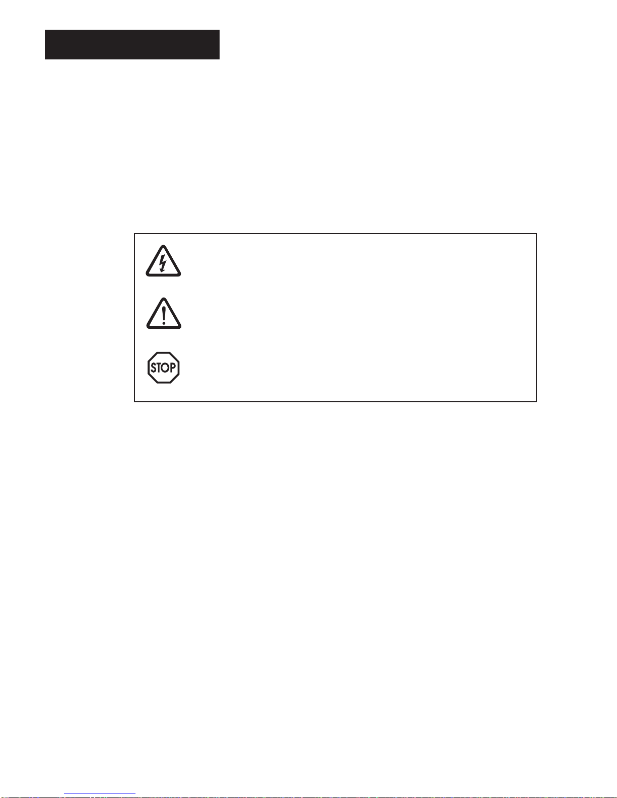
●Safety notes:
Always follow the safety notes contained in this User Manual.
Safety notes are marked as follows:
Electrical hazard, e.g. during live working
Mechanical hazard, e.g. when working on hoists
Important instructions for the safe and fault-free operation of the system, e.g.
presetting before commissioning.
Failure to follow these instructions may result in injury to people and damage to
property.
●General safety notes for bus systems:
The fieldbus option gives you a communications system which allows you to match the
MOVITRAC®31.. drive system to the specifics of your application to a very high degree. As
with all bus systems there is, however, the risk of parameters being changed, which will not
show outside (i.e. the inverter) but affect the behaviour of the inverter. This may result in
unexpected (not uncontrolled, though) system behaviour.
●In these instructions, cross-references are marked with a →, e.g.,
(→MC_SHELL) means: Please refer to the MC_SHELL User Manual for detailed information or
information on how to carry out this instruction.
(→section x.x) means: Further information can be found in section x.x of this User Manual.
●Each unit is manufactured and tested to current SEW-EURODRIVE technical standards and
specifications.
The manufacturer reserves the right to make changes to the technical data and designs as well
as the user interface herein described, which are in the interest of technical progress.
A requirement for fault-free operation and fulfilment of any rights to claim under guarantee is that
these instructions and notes are followed.
These instructions contain important information for servicing, they should therefore be kept in
the vicinity of the unit.
Important Notes
2
MOVITRAC
®
31.. Fieldbus Unit Profile
Phone: 800.894.0412 - Fax: 888.723.4773 - Web: www.clrwtr.com - Email: [email protected]

Preface
This
Fieldbus Unit Profile Manual
describes the operation of the MOVITRAC®31.. frequency inverter
when connected to a higher-level automation system via a fieldbus option pcb. In addition to
descriptions of all the fieldbus parameters, the various control concepts and potential applications
are dealt with in the form of brief examples of programs. The application examples are described
both in graphic form as well as in Simatic-S5 syntax. These application examples can be used with
almost all fieldbus option pcbs that fit the MOVITRAC®31.. inverter.
In addition to this Fieldbus Unit Profile User Manual, the following more detailed documentation on
fieldbus is also necessary in order to enable the MOVITRAC®31.. to be connected simply and
efficiently to the fieldbus system (e.g. PROFIBUS-DP, PROFIBUS-FMS, INTERBUS-S, etc.):
– User Manual for PROFIBUS (FFP 31..) option, part number 0922 6818
– User Manual for INTERBUS-S (FFI 31..) option, part number 0922 6915
– User Manual Communications Interfaces and Parameter List MOVITRAC®31..,
part number 0923 0580
The FFP 31.. PROFIBUS Option PCB User Manual describes the installation and commissioning of
the FFP 31.. PROFIBUS option pcb and gives further examples of applications specifically for setting
the inverter parameters via PROFIBUS-DP and PROFIBUS-FMS.
The FFI 31.. INTERBUS Option PCB User Manual describes the installation and commissioning of the
FFI 31.. INTERBUS-S option pcb and gives further examples of applications specifically for setting
the inverter parameters via INTERBUS-S.
The MOVITRAC®31.. Parameter List contains a list of all the inverter’s parameters that can be read
or written via the various communication interfaces such as the RS-232, RS-483 and via the fieldbus
interface.
Preface
MOVITRAC
®
31.. Fieldbus Unit Profile
3
Phone: 800.894.0412 - Fax: 888.723.4773 - Web: www.clrwtr.com - Email: [email protected]

Page
1 Introduction ............................................................. 6
2 Overview of Functions ..................................................... 7
3 Inverter Control with Process Data ........................................... 9
3.1 Commissioning the Inverter .............................................. 9
3.2 Process Data Configuration.............................................. 11
3.3 Process Data Description ............................................... 13
3.3.1 Setpoint Description for the PO Data ...................................... 12
3.3.2 PO Data Processing in the Inverter ........................................ 17
3.3.3 Actual Value Description of the PI Data..................................... 18
3.3.4 Enable Fieldbus Setpoints ............................................... 20
3.3.5 Scaling of the Process Data ............................................. 21
3.4 Definition of the Control Word ........................................... 25
3.4.1 Basic Control Block .................................................... 25
3.4.2 Control Word 1 ....................................................... 29
3.4.3 Control Word 2 ....................................................... 31
3.5 Definition of the Status Word ............................................ 33
3.5.1 Basic Status Block..................................................... 33
3.5.2 Status Word 1 ........................................................ 35
3.5.3 Status Word 2 ........................................................ 36
3.6 Active Input Terminal Functions .......................................... 37
3.7 Active Output Terminal Functions ......................................... 39
3.8 Integrated I/O-Module Functionality ....................................... 39
3.8.1 Scale of Functions..................................................... 39
3.8.2 Principle Mode of Operation ............................................. 40
4 Monitoring Functions . . . . . . . . . . . . . . . . . . . . . . . . . . . . . . . . . . . . . . . . . . . . 42
4.1 Fieldbus Timeout...................................................... 42
4.2 Timeout Response .................................................... 42
4.2.1 Rapid Stop with Warning ............................................... 43
4.2.2 Emergency Stop with Warning ........................................... 43
4.2.3 Immediate Switch-off with Warning ....................................... 43
4.2.4 Rapid Stop with Fault .................................................. 43
4.2.5 Emergency Stop with Fault .............................................. 43
4.2.6 Immediate Switch-off with Fault .......................................... 44
4.2.7 Switching to Standard Mode............................................. 44
4.2.8 No Response......................................................... 44
4.3 Fault Fieldbus Timeout ................................................. 45
5 Setting Inverter Parameters . . . . . . . . . . . . . . . . . . . . . . . . . . . . . . . . . . . . . . . . 46
5.1 Parameter Setting Procedure ............................................ 46
5.1.1 Index Addressing ..................................................... 46
5.1.2 Data Length/Coding.................................................... 46
5.2 Reading a Parameter (READ) ............................................ 47
5.3 Writing a Parameter (WRITE) ............................................ 48
Contents
4
MOVITRAC
®
31.. Fieldbus Unit Profile
Phone: 800.894.0412 - Fax: 888.723.4773 - Web: www.clrwtr.com - Email: [email protected]

5.4 Instructions to the User when Adjusting Parameters.......................... 48
5.4.1 Factory Setting ........................................................49
5.4.2 Saving to EEPROM.....................................................49
5.4.3 Parameter Lock .......................................................50
5.4.4 Download Parameter Block ..............................................50
5.5 Parameter Adjustment Return Codes.......................................50
5.5.1 Error Class ...........................................................50
5.5.2 Error Code ...........................................................51
5.5.3 Additional Code .......................................................51
5.5.4 Special Return Codes (Special Cases) ..................................... 52
6 Diagnosis Using the Fieldbus Monitor Parameters............................. 53
6.1 Diagnosis of Process Output Data .........................................53
6.2 Diagnosis of Process Input Data ..........................................54
6.3 MC_SHELL Fieldbus Monitor .............................................55
6.3.1 Diagnosis Using the Fieldbus Monitor ..................................... 55
6.3.2 Control Using the Fieldbus Monitor ........................................55
6.4 Verification of Parameter Adjustment ..................................... 56
6.5 Information about the Fieldbus Option PCB..................................56
6.5.1 Process Data Configuration ..............................................56
6.5.2 Fieldbus Option PCB Type ...............................................56
6.5.3 Fieldbus Baud Rate.....................................................56
6.5.4 Fieldbus Address ......................................................56
7 Application Examples .....................................................57
7.1 Control Using 2 Process Data Words.......................................57
7.1.1 Objective.............................................................57
7.1.2 Commissioning .......................................................58
7.1.3 S5 Application Program .................................................60
7.1.4 Start-up Parameter Setting via a Fieldbus ...................................61
7.2 Control Using 3 Process Data Words.......................................61
7.2.1 Objective.............................................................62
7.2.2 Commissioning .......................................................62
7.2.3 S5 Application Program .................................................65
7.2.4 Start-up Parameter Setting via Fieldbus.................................... 66
7.3 Relative Speed / I/O-Module Functionality ...................................66
7.3.1 Commissioning .......................................................67
7.3.2 S5 - Application Program................................................69
7.4 Positioning with IPOS via Fieldbus.........................................71
7.4.1 Objective.............................................................71
7.4.2 Implementation Possibilities with IPOS .................................... 72
7.4.3 Process Data Description for Positioning Mode ..............................72
7.4.4 Commissioning .......................................................73
7.4.5 S5 Application Program .................................................76
Index .......................................................................77
Contents
MOVITRAC
®
31.. Fieldbus Unit Profile
5
Phone: 800.894.0412 - Fax: 888.723.4773 - Web: www.clrwtr.com - Email: [email protected]
Table of contents
Other SEW DC Drive manuals


