Festo OVEM-05 User manual

Vacuum generator
OVEM−Ū−1P/1N
Festo AG & Co. KG
Postfach
D−73726 Esslingen
++49/711/347−0
www.festo.com
Operatinginstructions 754851
1007NH
Original: de
1 Product description
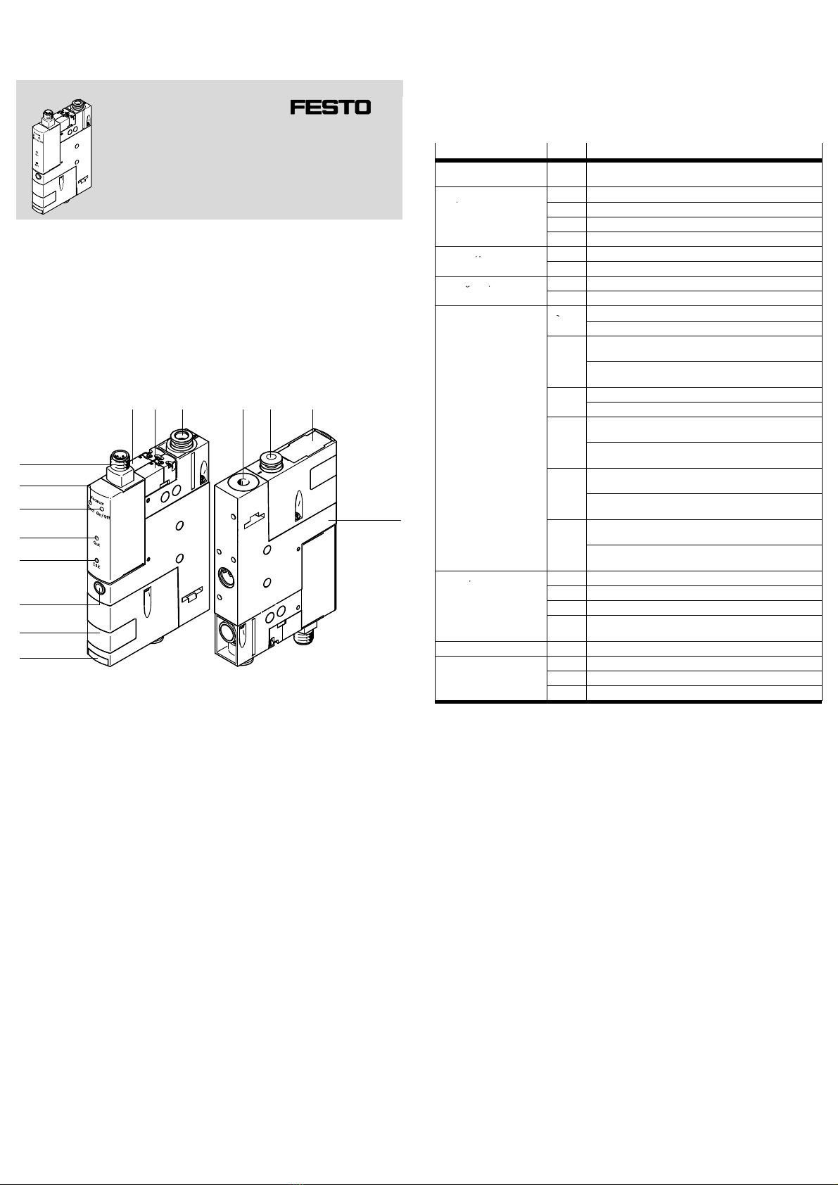
1.1 Overview
aJ
9
8
aD
2 3
aA
1
aB
aC
aE
7
4 5 6
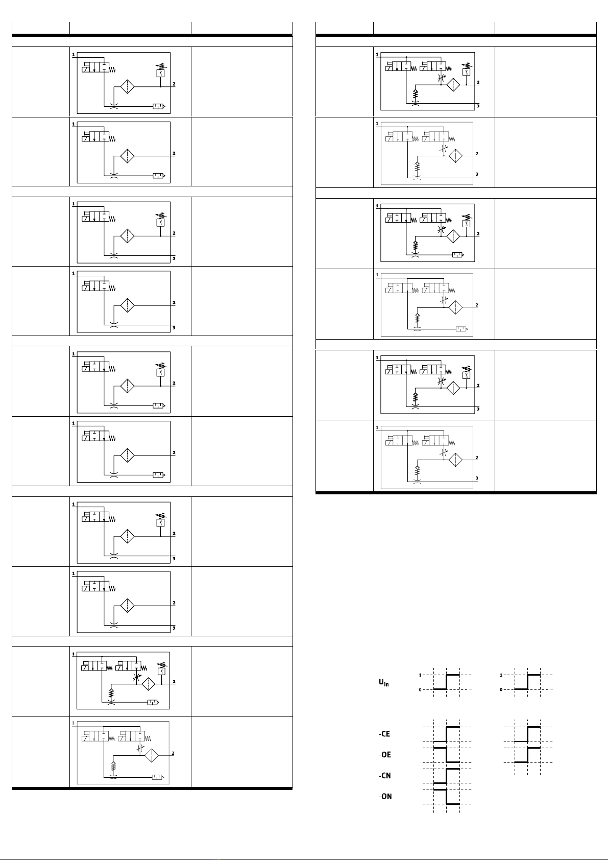
1Solenoid valve, ejector pulse (E)
2Solenoid valve, vacuum
ON/OFF(V)
3Supply port
4Exhaust port/silencer
5Vacuum port
6Replaceable filter element
7Housing with mounting holes
8Slide for changing the filter
9Filter housing with inspection
window
aJ Flow control screw for adjusting
the intensity of the ejector pulse
aA EDIT button1)
aB LED for switching output Out1)
aC LED for switching input Vacuum
On/Off
aD LED for switching input Ejector
pulse
aE Plug for electrical connection
(M12)
1) LED and EDIT button not present on models without vacuum sensor
Fig.1 Operating elements and connections
1.2 Key features
Integrated solenoid valve for control of compressed air supply for vacuum gen
eration, available with two different switching functions: NC/NO
NC− de−energised when closed, meaning there is no vacuum generation when
the solenoid valve is in normal position (−CE,−CN)
NO− de−energised when open, meaning vacuum is generated when the sole
noid valve is in normal position (−OE, −ON)
Integrated solenoid valve for control of ejector pulse for rapid purging of vacuum
and safe set−down (−CE, −OE)
Flow control screw for controlling the ejector pulse (−CE, −OE)
Integrated vacuum sensor with switching output and Teach function (−1P, −1N)
Operating statuses of the solenoid valves displayed by LEDs
Solenoid valves can be operated with mechanical manual override
Filtering of the process air to protect the vacuum generator
Open, integrated silencer to reduce contamination of the vacuum generator
(−QO, −GO, −PO)
Various pneumatic connection alternatives (QS fitting: −QS, −QO, −PL, −PO;
female thread: −GN, −GO)
Electrical connection via M12 plug
Various output stages (05/07/10/14) vacuum types (H/L)
Anon−return valve prevents purging of vacuum if vacuum generation is inter
rupted (−CE, −OE)
Integrated protection against reverse polarity and overload protection for
switching output
Features Type Design
Vacuum generator OVEM Vacuum generator with solenoid valve for vacuum
valveON/OFF and manual override
Nominal size of Laval
l
−05 0.45mm
nozzle −07 0.7mm
−10 0.95mm
−14 1.4mm
Vacuum type −H High vacuum
yp
−L High suction capacity
Housing size/width −B 20mm wide, ISO standard
g/
−BN 20mm wide, NPT
Pneumatic connections −QS All ports with QS fittings (−B−QS)
Q
All ports with QS fittings in inch sizes (−BN−QS)
−QO Supply/vacuum port with QS fittings, exhaust port with
open silencer (−B−QO)
Supply/vacuum port with QS fittings in inch sizes, exhaust
port with open silencer (−BN−QO)
−GN All ports with female G thread (−B−GN)
All ports with female NPT thread (−BN−GN)
−GO Supply/vacuum port with female G threads, exhaust port
with open silencer (−B−GO)
Supply/vacuum port with female NPT threads, exhaust
port with open silencer (−BN−GO)
−PL Prepared for supply strip, vacuum port and exhaust port
with QS fittings (−B−PL)
Prepared for supply strip, vacuum port and exhaust port
with QS fittings in inch sizes (−BN−PL)
−PO Prepared for supply strip, vacuum port with QS fitting,
exhaust port with open silencer (−B−PO)
Prepared for supply strip, vacuum port with QS fitting in
inch size, exhaust port with open silencer (−BN−PO)
Normal position of the va −ON NO, normally open (vacuum generation)
p
cuum generator −OE NO, normally open (vacuum generation) with ejector pulse
−CN NC, normally closed (no vacuum generation)
−CE NC, normally closed (no vacuum generation) with ejector
pulse
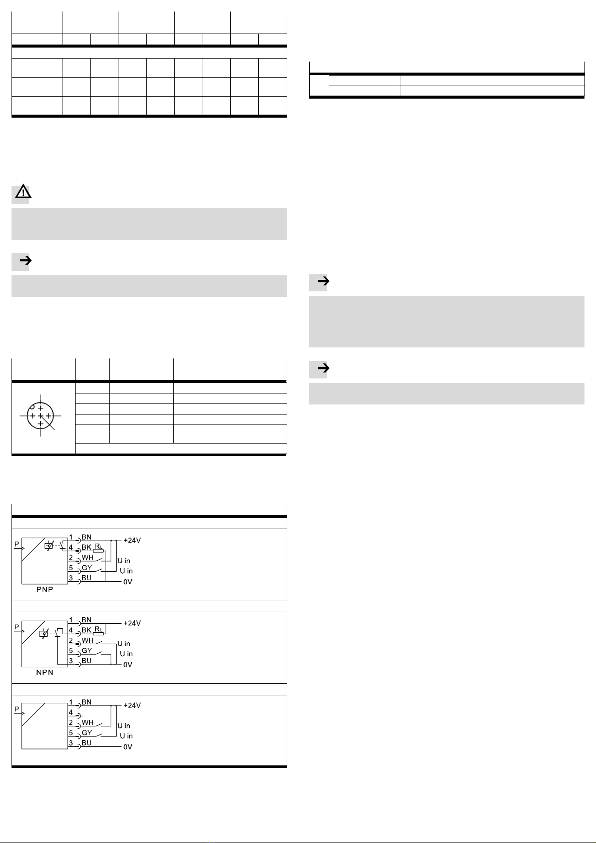
Electrical connection −N Plug M12 (5−pin)
Vacuum sensor No vacuum sensor (PNP switching input)
−1P 1switching output PNP
−1N 1switching output NPN
Fig.2 Overview of variants
2 Function and application
The vacuum generator type OVEM is designed for generating a vacuum. The vac
uum generated is used together with a suction gripper to create a force that can
grip a workpiece so that it can be transported. The vacuum generator is available
with a variety of pneumatic and electric switching functions.
The taught setpoint value for the generated vacuum is monitored via an integrated
vacuum sensor (−1P, −1N). If the setpoint value is reached or if it is not reached due
to malfunctions (e.g.leakage, dropped workpiece), the vacuum sensor emits an
electrical signal and the Out LED indicates whether or not the setpoint was
reached.
The compressed air supply for vacuum generation is controlled by an integrated
solenoid valve. The solenoid valve can be supplied with two different switching
functions, NC and NO. The vacuum is generated as soon as compressed air is ap
plied to the vacuum generator and the electrical power supply is switched on
(NC: −CE, −CN) or off (NO: −OE, −ON) as defined by the switching function of the
solenoid valve2.
The integrated solenoid valve1can be used to control and generate an ejector
pulse to release the workpiece safely from the suction cup and to purge the vac
uum rapidly.

2.1 Functions
Type Symbol Function
−QO/−GO−CN−Ū
−1P/1N NC solenoid valve for vacuum
ON/OFF with vacuum sensor and
silencer
Without vacuum
sensor
NC solenoid valve for vacuum
ON/OFF with silencer
−QS/−GN−CN−Ū
−1P/1N NC solenoid valve for vacuum
ON/OFF with vacuum sensor
Without vacuum
sensor
NC solenoid valve for vacuum
ON/OFF
−QO/−GO−ON−Ū
−−1P/1N NO solenoid valve for vacuum
ON/OFF with vacuum sensor and
silencer
Without vacuum
sensor
NO solenoid valve for vacuum
ON/OFF with silencer
−QS/−GN−ON−Ū
−1P/1N NO solenoid valve for vacuum
ON/OFF with vacuum sensor
Without vacuum
sensor
NO solenoid valve for vacuum
ON/OFF
−QO/−GO−CE−Ū
−1P/1N NC solenoid valve for vacuum
ON/OFF, solenoid valve for ejector
pulse, ejector pulse adjustable
using adjusting screw, integrated
non−return valve for maintain
vacuum", with vacuum sensor and
silencer
Without vacuum
sensor
NC solenoid valve for vacuum
ON/OFF, solenoid valve for ejector
pulse, ejector pulse adjustable
using adjusting screw, integrated
non−return valve for maintain
vacuum", with silencer
Type Symbol Function
−QS/−GN−CE−Ū
−1P/1N NC solenoid valve for vacuum
ON/OFF, solenoid valve for ejector
pulse, ejector pulse adjustable
using adjusting screw, integrated
non−return valve for maintain
vacuum", with vacuum sensor
Without vacuum
sensor
NC solenoid valve for vacuum
ON/OFF, solenoid valve for ejector
pulse, ejector pulse adjustable
using adjusting screw, integrated
non−return valve for maintain
vacuum"
−QO/−GO−OE−Ū
−1P/1N NO solenoid valve for vacuum
ON/OFF, solenoid valve for ejector
pulse, ejector pulse adjustable
using adjusting screw, integrated
non−return valve for maintain
vacuum", with vacuum sensor and
silencer
Without vacuum
sensor
NO solenoid valve for vacuum
ON/OFF, solenoid valve for ejector
pulse, ejector pulse adjustable
using adjusting screw, integrated
non−return valve for maintain
vacuum", with silencer
−QS/−GN−OE−Ū
−1P/1N NO solenoid valve for vacuum
ON/OFF, solenoid valve for ejector
pulse, ejector pulse adjustable
using adjusting screw, integrated
non−return valve for maintain
vacuum", with vacuum sensor
Without vacuum
sensor
NO solenoid valve for vacuum
ON/OFF, solenoid valve for ejector
pulse, ejector pulse adjustable
using adjusting screw, integrated
non−return valve for maintain
vacuum"
Fig.3 Circuit symbols for the functions
2.2 Switching output and switching inputs
The vacuum is monitored with the aid of a piezoresistive sensor element. The vac
uum sensor converts pneumatic pressure values and supplies electrical signals.
When the taught switching point is reached, the vacuum sensor closes a circuit,
supplying an electrical signal. This signal can be used for control functions.
The vacuum generator can be connected to higher−level systems by means of a
switching output (−1P, 1N) and switching inputs. The switching output is configured
as normally open. The output’s switching function is defined as a threshold value
comparator.
The input signals determine the actuation of the solenoid valves for control of the
compressed air and the ejector pulse.
ON
ON
ON
ON
ON
ON
OFF
OFF
OFF
OFF
OFF
OFF
Solenoidvalve 1Solenoidvalve 2
Input signal
Switching
position
of solenoid valve
Fig.4 Switching characteristics of switching inputs

Variant Switching output Switching inputs
−1P Switching output
positive switching
Switching inputs
positive switching
−1N Switching output
negative switching
Switching inputs
negative switching
Fig.5 Variants, switching output and switching inputs
2.3 Switching point SP and hysteresis Hy
Threshold value comparator
NO (normally open)
Fig.6 Settings for switching points (SP), hysteresis (Hy) and buffer (FR)
Note
The switching point is derived from the Teach pressure and the buffer. A buffer
(35% of the Teach pressure) is deducted from the Teach pressure (SP = TP
0.35*TP). For example, with a Teach pressure of 0.5bar, a switching point of
0.33bar is set.
The hysteresis has a fixed value.
3 Requirements for product use
Note
Improper handling can result in malfunctions.
· Make sure that the following specifications are always observed.
· Compare the maximum values specified in these operating instructions with
your actual application (e.g. operating media, pressures, forces, torques, tem
peratures, masses, speeds, operating voltages, flow rates).
· Take into consideration the ambient conditions at the location of use.
· Please comply with national and local safety laws and regulations.
· Remove all transport packing such as protective wax, plastic wrap (polyamide),
caps (polyethylene), cardboard boxes (except for the covers on the pneumatic
ports).
The packing is intended for recycling (except for: oiled paper = general waste).
· Use the product in its original state. Unauthorised modification is not permitted.
4 Installation
The product can be fitted in any position. Mount the vacuum generator and con
nect its tubing in such a way that no condensation from the compressed air lines
can gather in the device.
4.1 Mechanical
Direct mounting
Fig.7 Direct mounting
· Mount the vacuum generator at the intended position with two screws (size of
the mounting screws èFig.8); fasten with max. torque 2.5Nm.
We recommend that suitable washers be used.
or
· Mount the vacuum generator on its back cover with 4 screws, size M3, with max.
torque 0.8Nm.
OVEM Size of mounting screws
05/07/10 M5
14 M4
Fig.8 Size of mounting screws
Mounting with accessories
With H−rail mounting kit
1
Fig.9 H−rail mounting
1. Mount the H−rail mounting on the back cover of the vacuum generator with
4screws, size M3, with max. torque 0.8Nm.
2. Hook the vacuum generator onto the H−rail and press in the direction of the
arrow.
3. Secure the vacuum generator to the H−rail with screw 1, fastening it with max.
torque 1Nm.
With mounting bracket
Fig.10 Mounting bracket
· Mount the vacuum generator at the intended position with two screws
(size of the mounting screws èFig.8); fasten with max. torque 2.5Nm.
We recommend that suitable washers be used.
The vacuum generator can also be mounted on a common supply manifold with up
to 8 positions. Information on mounting èAssembly instructions OABM−P−Ū.
OVEM−ŪType of mounting
Q−/−G− With screws or accessories, èAccessories
−P− With common supply manifold, èAccessories
Fig.11 Key feature Mounting type
4.2 Pneumatic
· Connect appropriate tubing to the QS push−in connectors (−QS, −QO, −PL, −PO).
We recommend that tubing of type PUN−6 be used.
· When selecting the tubing for tubing connection on a vacuum generator with
threaded ports (−GN, −GO), be mindful of the minimum internal diameter for
tubing stated in Fig.12.

Type OVEM−05
GN/GO
OVEM−07
GN/GO
OVEM−10
GN/GO
OVEM−14
GN/GO
Tube length < 0.5m < 2m < 0.5m < 2m < 0.5m < 2m < 0.5m < 2m
Minimum tube internal diameter [mm]
Port1
Compressed air
1 2 1.5 2 2 3 3 4
Port2
Vacuum
2 3 3 4 4 5 5.5 6
Port3
Exhaust
2 3 3 4 4 5 5.5 6
Fig.12 Minimum tube internal diameters
· With OVEM−07/10/14, you can extend the silencer if needed using a silencer
extension (èchapter11Accessories).
4.3 Electrical
Warning
Use only power sources which guarantee reliable electrical isolation of the
operating voltage as per IEC/DIN EN 60204−1. Observe also the general
requirements for PELV power circuits as per IEC/DINEN60204−1.
Note
Long signal lines reduce the resistance to interference.
· Make sure that the signal cables are not longer than 30m.
· Make sure that the operating voltage supply is 24 VDC ±15 %.
The solenoid coils and electrical components could be damaged if the maximum
permitted switching voltage is exceeded.
· Connect the cable socket to the plug connectoraE.
· Wire the vacuum generator as shown in Fig.13.
Plug connector2)
5−pin M12
Pin Wire colours 1) Allocation
11 Brown (BN) Supply voltage +24VDC
1
2 White (WH) Switching input for vacuum ON/OFF
24
3 Blue (BU) 0 V
24
4 Black (BK) Switching output (Out)3)
5
3
5 Grey (GY) Switching input for ejector pulse
ON/OFF
3
1) Using the plug socket with cable as specified in the chapter Accessories".
2) Max. tightening torque 0.3Nm.
3) Pin 4 is not connected on models without vacuum sensor
Fig.13 Pin allocation
Circuit diagrams for OVEM−...
OVEM−Ū−1P
OVEM−Ū−1N
OVEM without vacuum sensor
Fig.14 Circuit diagrams for vacuum generator
5 Fast commissioning with factory setting
The vacuum generator is available with the following factory settings:
· Switching characteristics of the electrical output: threshold value comparator
· Switching element function of the electrical output: NO (normally open con
tact)
Factory settings for OVEM−Ū
Out Switching point (SP) 0.4bar
(Fixed hysteresis (HYS) 20mbar)
Fig.15 Factory settings
If you do not wish to use the factory settings, you can teach a switching point for
the switching output (èchapter6Commissioning). The factory settings are not
reproducible.
6 Commissioning
· When transporting workpieces, make sure that:
Nobody is standing under the workpiece
There are no objects within the transporting path of the workpiece (e.g. by
means of a protective screen).
· Avoid long tubing and large volumes of air between the suction grippers and the
vacuum generator.
A large volume leads to long evacuation times and possibly incorrect settings on
the vacuum sensor.
· Take into account accelerations, external influences, etc. on the workpiece when
setting the required holding force.
Note
Unintentional pressing of the EDIT button (for longer than two seconds) may
cause a modification of the preset switching pressure.
· Make sure that the EDIT button is only pressed intentionally. Otherwise a
switching pressure of 0 bar would be set if there was no operating pressure,
for example.
Note
To prevent damage to the EDIT button, press the EDIT button with a blunt object
only.
6.1 Building up the vacuum:
1. Pressurise the vacuum generator with an operating pressure at the supply
port 3.
2. Switch on the operating voltage.
3. Energise the switching input for vacuum ON/OFF.
èThe solenoid valve2(−CN, −CE) is opened (or closed in the case of −OE,
−ON). The compressed air flows through the vacuum generator and gener
ates a vacuum accordingly at the vacuum port5. The vacuum can be ad
justed by modifying the operating pressure.
6.2 Setting the vacuum sensor:
The setting of the vacuum sensor for monitoring the vacuum depends on the ap
plication.
The vacuum generator is preset at the factory (factory settings èchapter5 Fast
commissioning). These settings can be adapted to the application quickly by
teaching a switching point.
Teac hing a switching point:
1. Switch on the operating voltage.
2. Set the desired Teach pressure (e.g. object gripped).
3. Press and hold the EDIT button aA >2sec.
èThe LEDOutaB flashes.
4. Release the EDIT buttonaA.
èThe current Teach point (TP) minus the buffer is saved as the switching point
(SP) and is applied for the switching output.
5. Carry out a test run, varying the pressure to check whether the vacuum gener
ator’s switching output switches as desired.
6.3 Setting the ejector pulse (−OE, −CE):
The vacuum generator must be in its initial position.
The workpiece must be held securely against the suction gripper by the vacuum
generated.
The intensity of the ejector pulse can be set.
You can set the intensity of the ejector pulse by adjusting the flow control
screwaJ.
1. Screw the flow control screwaJ all the way in by turning it clockwise.
èThis closes off the channel for the ejector pulse. No ejector pulse is gener
ated.
2. Unscrew the flow control screw until the required ejector pulse intensity is
reached.
3. Test the settings for the ejector pulse prior to commissioning.

6.4 Purging the vacuum:
OVEM−Ū−CN/−ON
· Cut off the compressed air supply by switching the input voltage off (in the case
of −CN) or on (in the case of −ON).
èThe vacuum port5is supplied with air. The workpiece detaches itself from
the suction gripper.
OVEM−Ū−CE/−OE
When the solenoid valve for ejector pulse1is switched on, an ejector pulse is
generated.
èThe vacuum port5is supplied with air. The workpiece detaches itself from
the suction gripper.
Note
When large suction cups are used, flow resistance in the suction cup as the cup
lifts away from the workpiece can cause the buildup of a vacuum independent of
the generating device. This might mean that the workpiece being set down does
not detach from the suction cup, even when the ejector pulse is set to a long
duration.
Therefore, switch on the solenoid valve for ejector pulse 1shortly before the
suction cup is lifted away, to ensure that the ejector pulse is active as the suction
cup lifts away.
7 Operation
Note
The settings last saved are retained in the event of a power failure.
7.1 Manual override
Fig.16 Operating the manual override
The manual override can be used to switch the solenoid valve manually when it is
not being actuated or not supplied with power. The manual override is non−detent
ing (automatic reset).
· Press down the plunger of the manual override with a blunt pin.
The solenoid valve is activated.
· Remove the pin.
The plunger of the manual override and the solenoid valve move to their normal
position.
7.2 Vacuum generator status display
LED Status Meaning
Out Off Switching point not reached
Lights up Switching point reached
Flashing Switching point being taught
Vacuum On/Off CE/CN Off Solenoid valve for vacuum ON/OFF is not
switched, no vacuum generated
Lights up Solenoid valve for vacuum ON/OFF is
switched, vacuum is generated
OE/ON Off Solenoid valve for vacuum ON/OFF is
switched, vacuum is generated
Lights up Solenoid valve for vacuum ON/OFF is not
switched, no vacuum generated
Eject Off Solenoid valve for ejector pulse is not
switched, no ejector pulse generated
Lights up Solenoid valve for ejector pulse is switched, an
ejector pulse is generated
Fig.17 Vacuum generator status display
8 Maintenance
· Switch off the following sources of energy before cleaning the exterior of the
device:
Operating voltage
Compressed air supply
·Ifnecessary, clean the outside of the vacuum generator.
Permitted cleaning agents are soap suds (max. +60°C) and all non−abrasive
agents.
· Check whether the air filter is contaminated.
The filter can be inspected visually through the transparent filter cover.
Cleaning the air filter:
1
2
Fig.18 Removing/installing the filter
1. Vent the vacuum generator.
2. Carefully pull out the slide1on the filter2up to the first detent. The slide1
must stay in this position on the filter.
3. Pull the filterout.
(Use a screwdriver to help to bring out the filter if necessary)
4. Clean the filter2, for example with cleaner’s solvent.
5. Push the filter2into its housing using the slide1.
6. Push in the slide1.
9 Eliminating malfunctions
Malfunction Possible cause Remedy
Workpiece does not de
tach from suction cup
A vacuum built up when lifting
large suction cups away quickly
Increase the intensity of the
ejector pulse
Lift the suction cup away from
the workpiece more slowly
Set the ejector pulse to be
active when lifting the suction
cup away
Tubing used between the suc
tion cup and vacuum generator
is wrongly sized (tube is too long
and/or tube internal diameter is
too small)
Replace the tubing; tubing
requirementsèchapter4.2
Flow control screw is closed Open the flow control screw
No LED display for switch
ing inputs
Supply voltage not applied or no
permitted operating voltage
Switch on supply voltage/
maintain permitted operating
voltage range
Connections swapped (incorrect
polarity)
Wire the device as per the dia
gram
No control signal Check the control system
Device defective Replace the device
No LED display for switch Pressure failure Eliminate pressure failure
py
ing output Vacuum generator operated with
non−permitted medium
Replace the vacuum generator
and operate only with com
pressed air
LED display or switching
output does not react in
Short circuit or overload at the
output
Eliminate short circuit/overload
output
does
not
react
in
accordance with the set
tings made
Incorrect switching point taught
(e.g. at 0 bar)
Repeat Teach procedure
(èchapter6.2)
Device defective Replace the device
Fig.19 Eliminatingmalfunctions
10 Disassembly
1. Switch off the following sources of energy before disassembling:
Operating voltage
Compressed air supply
2. Disconnect the electrical and pneumatic connections to the vacuum generator.
3. Remove the vacuum generator.

11 Accessories
Name OVEM−05 OVEM−07/10 OVEM−14
Connecting cable M12x1, 5−pin, 2.5m NEBU−M12G5−K−2.5−LE5
Connecting cable M12x1, 5−pin, 5m NEBU−M12G5−K−5−LE5
H−rail mounting OABM−H
Mounting bracket HRM−1
Silencer extension UOMS−¼ UOMS−¼
Common supply manifold OABM−P−4
pp y
OABM−P−6
OABM−P−8
Blanking plug OASC−G1−P
Fig.20 Accessories
12 Technical data
OVEM −05 −07/−10 −14
Operating pressure [bar] 2Ū8
Operating
pressure
[bar]
QS/GN/PL−Ū−1P/1N: 2Ū6
Operating medium Filtered, unlubricated compressed air,
grade of filtration 40ìm
Ambient temperature [°C] 0Ū50
Temperature of medium [°C] 0Ū50
Nominal operating voltage [V DC] 24 ±15%
Idle current1) [mA] <80
Coil characteristics 24 V DC [W] Low−current phase: 0.3
[]
High−current phase: 2.55
Time until current reduction [ms] <80
Ready−state delay [ms] ≤500
Switching output
Max. output current [mA] 100
Voltage drop [V] ≤1.5
Capacitive load max. DC [nF] ≤100
Reaction time [ms] <12 ≤22 ≤35
Protective functions
Inductive protective circuit Adapted to MZ, MY, ME coils
Protection against short circuit Yes
Overload protection Yes
Reverse polarity protection For all electrical connections
Protection class IP65
Electrical protection class 3
Interference immunity See declaration of conformity (www.festo.com)
Interference emission See declaration of conformity (www.festo.com)
Vibration resistance As per DIN/IEC 68/EN 60068 part 2−6:
0.35 mm travel at 10 Ū60 Hz,
5 g acceleration at 60 Ū150 Hz
Shock resistance As per DIN/IEC 68/EN 60068 part 2−27:
30 g acceleration at 11ms duration (half−sine)
Max. permitted signal line length [m] 30
Overload pressure at vacuum port [bar] 1P/1N: ≤5
Overload
pressure
at
vacuum
port
[bar]
Without vacuum sensor: ≥10
Pressure measuring range3) [bar] 1Ū0
Repetition accuracy of switching
value2)3)
[% FS] Max. ±0.3
Temperature co−efficient2)3) [% FS/K] ±0.05
Setting range for threshold values3) [bar] 1Ū0
Hysteresis, fixed3) [mbar] 20
1) Both solenoid valves are actuated
2) % FS = % of the final value in the measuring range (full−scale)
3) Technical feature only relevant for models with vacuum sensor
Fig.21 Technical data
Other manuals for OVEM-05
3
This manual suits for next models
9
Table of contents
Other Festo Portable Generator manuals
Popular Portable Generator manuals by other brands

Ferroli
Ferroli OPERA 70 Instructions for use, installation and maintenance

Viessmann
Viessmann Vitobloc 200 EM-50/81 operating instructions

Omega
Omega BSG 6500R user guide

Bryant
Bryant ASPAS1BBA007 Diagnostic repair manual

EINHELL
EINHELL TC-PG 10/E5 Original operating instructions

Ribimex
Ribimex PRGE0800 User and maintenance manual

Briggs & Stratton
Briggs & Stratton Elite 030206 owner's manual

Powermate
Powermate PC0496503.17 manual

Briggs & Stratton
Briggs & Stratton 040234-1 Illustrated parts list

Hyundai
Hyundai HY4000SEi user manual

ATI Technologies
ATI Technologies SX080 instruction manual

Team Orion
Team Orion dDrive instruction manual