Seyeon FlexWatcher FW2170 User manual

FW2170 User’s Manual
M4067-00 1 Seyeon Tech Co., Ltd
FW2170 User’s Manual
(Product Guide)
Version 4.16(Rev.E)
Sep. 27, 2012
Class A Digital Device (industrial & commercial environment)
This equipment has been tested and found to comply with the limits for a Class A digital device, pursuant to CE
and FCC Rules. These limits are designed to provide reasonable protection against harmful interference when the
equipment is operated in a commercial environment. This equipment generates, uses and can radiate radio
frequency energy and, if not installed and used in accordance with the instruction manual, may cause harmful
interference to radio communications. Operation of this equipment in a residential area is likely to cause harmful
interference in which case the user will be required to correct the interference at his own expense.

FW2170 User’s Manual
M4067-00 2 Seyeon Tech Co., Ltd
FW2170 User’s Manual
Document Part Number: M4067-00
Document Version: 4.16(Rev.E)
Revised: September 27, 2012
About This Document
This document is prepared for users of FW2170 supplied by Seyeon Tech Co., Ltd. It is assumed that the
users are familiar with Microsoft Windows operating systems and Web browsers such as Internet Explorer.
It is also assumed that the users are well aware of how to install and use the network equipment such as
LAN, Hub, router, and having basic knowledge of network terminologies. If you have any questions
regarding network installations, please contact your network equipment vendor or network administrator
or Internet service providers.
For updated contents, detailed features and other applications from Seyeon Tech, please refer to the user’s
manual in CD-ROM provided with the product you purchased, or visit Seyeon Tech’s Internet homepage at
http://www.flexwatch.com/.
Copyright Notice
Copyright © 2012 Seyeon Tech Co., Ltd. All rights reserved.
No part of this document may be reproduced in any form or by any means without the prior written
permission of Seyeon Tech Co., Ltd.
Disclaimer
Seyeon Tech Co., Ltd. (Seyeon Tech) Makes no representations or warranties with respect to the contents
hereof. In addition, information contained herein is subject to change without notice. Every precaution has
been taken in the preparation of this manual, nevertheless, Seyeon Tech assumes no responsibility for
errors or omissions or any damages resulting from the use of the information contained in this document.
Trademarks
FlexWATCH®and FlexWATCH®Logo are trademarks of Seyeon Tech Co., Ltd.
Windows and Internet Explorer are a trademark of Microsoft Corporation.
All other trademarks belong to their respective owners.
Technical Support
For technical support call, email, or visit our web site.
Telephone: +82-2-2192-6840~1
Email: sales@flexwatch.com
Web site: http://www.flexwatch.com or http://www.seyeon.co.kr

FW2170 User’s Manual
M4067-00 3 Seyeon Tech Co., Ltd
Contents
1. PRODUCT OVERVIEW ......................................................................................................................... 5
1.1. FW2170 ........................................................................................................................................................................ 5
1.2. KEY FEATURES ................................................................................................................................................................6
1.3. PRELIMINARY SPECIFICATION........................................................................................................................................ 7
1.4. FW2170 PACKING LIST ................................................................................................................................................8
1.5. NETWORK DIAGRAM......................................................................................................................................................9
1.5.1.
Private Network.....................................................................................................................................................9
1.5.2.
Wide Area Network............................................................................................................................................. 9
1.5.3.
FW2170 with the existing Analog System..............................................................................................10
1.6. APPLICATION .................................................................................................................................................................11
2. HARDWARE DESCRIPTION .............................................................................................................. 12
2.1. FRONT VIEW..................................................................................................................................................................12
2.2. REAR VIEW.....................................................................................................................................................................13
2.2.1.
CTL Port Description .........................................................................................................................................14
2.2.2.
Speaker V-out Jack Description...................................................................................................................14
2.2.3.
MIC Jack Description ........................................................................................................................................14
3. FW2170 INSTALLATION AND BASIC SETUP ................................................................................ 15
3.1. BEFORE INSTALLATION.................................................................................................................................................15
3.2. FACTORY DEFAULT SETTINGS .....................................................................................................................................15
3.3. INSTALLING FW2170 ..................................................................................................................................................15
3.4.
NETWORK CONFIGURATION
.......................................................................................................................................15
4. ADMIN MENU .................................................................................................................................... 17
4.1. ENTERING ADMIN MENU............................................................................................................................................17
4.2. ADMIN MENU STRUCTURE .........................................................................................................................................18

FW2170 User’s Manual
M4067-00 4 Seyeon Tech Co., Ltd
5. SYSTEM CONFIGURATION MENU .................................................................................................. 18
5.1. SERVER NAME SETUP...................................................................................................................................................19
5.2. ADMIN PASSWORD ......................................................................................................................................................19
6. NETWORK CONFIGURATION .......................................................................................................... 20
6.1. NETWORK CONFIGURATION .......................................................................................................................................20
6.1.1.
Static IP Configuration .....................................................................................................................................20
6.1.2.
DHCP Client Configuration ............................................................................................................................21
6.2. NETWORK PORTS..........................................................................................................................................................21
6.3. VIEW NETWORK STATUS .............................................................................................................................................22
6.4. NETWORK STATUS NOTIFY .........................................................................................................................................22
7. DISPLAY CONFIGURATION ............................................................................................................244
7.1. DISPLAY OUTPUT DEVICE............................................................................................................................................24
7.1.1.
Channel Configuration.....................................................................................................................................25
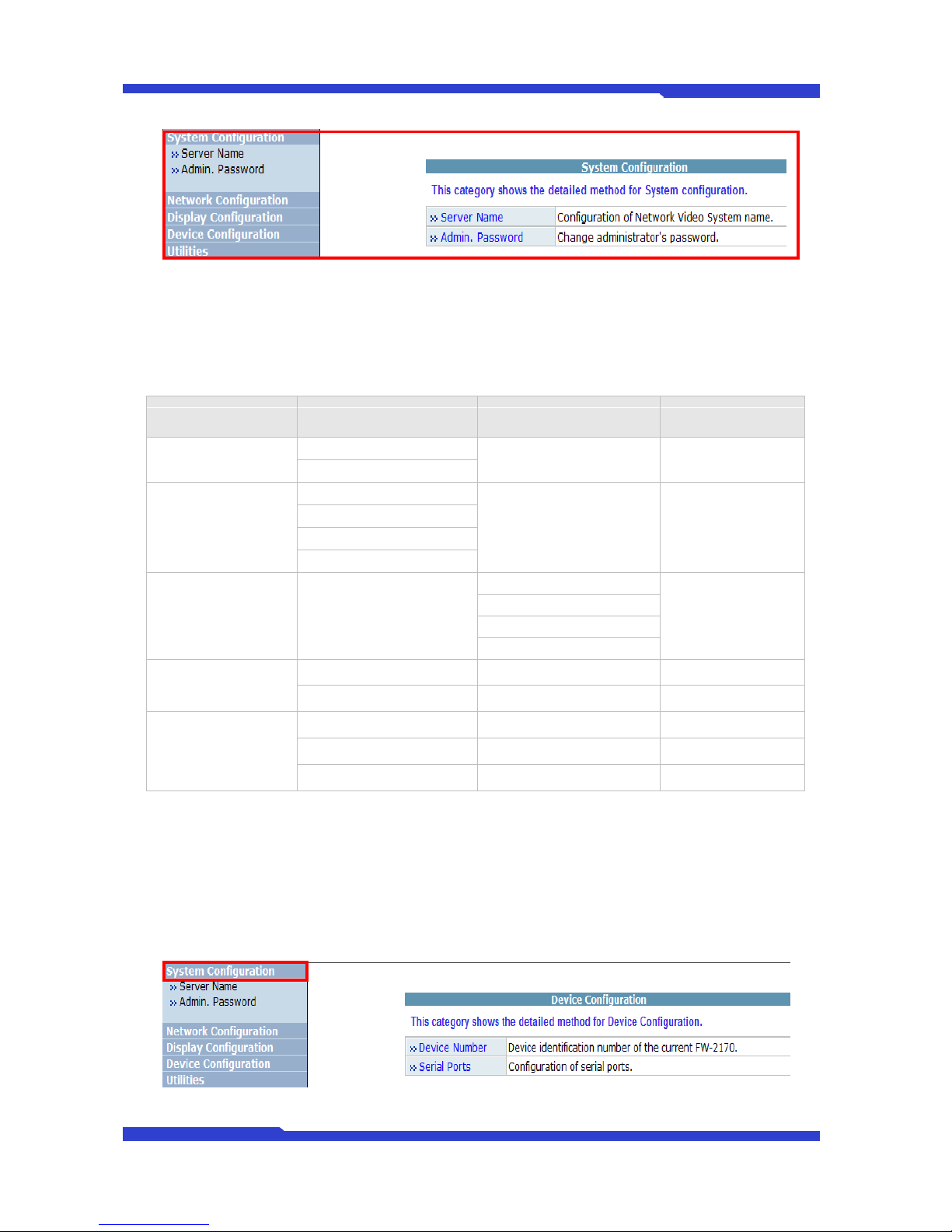
8. DEVICE CONFIGURATION ................................................................................................................ 26
8.1. DEVICE NUMBER CONFIGURATION............................................................................................................................26
8.2. SERIAL PORTS CONFIGURATION.................................................................................................................................26
8.2.1.
Transparent Mode..............................................................................................................................................27
9. UTILITIES ............................................................................................................................................. 28
9.1. REBOOT ..........................................................................................................................................................................28
9.2. FACTORY DEFAULT .......................................................................................................................................................28
9.3. SYSTEM UPDATE ...........................................................................................................................................................29
9.3.1.
All (Kernel, RAM disk, System, Web) Update........................................................................................30
9.3.2.
System and Web Update................................................................................................................................32
9.3.3.
Web Only Update ..............................................................................................................................................32
FW2170 User’s Manual
M4067-00 5 Seyeon Tech Co., Ltd
1. Product Overview
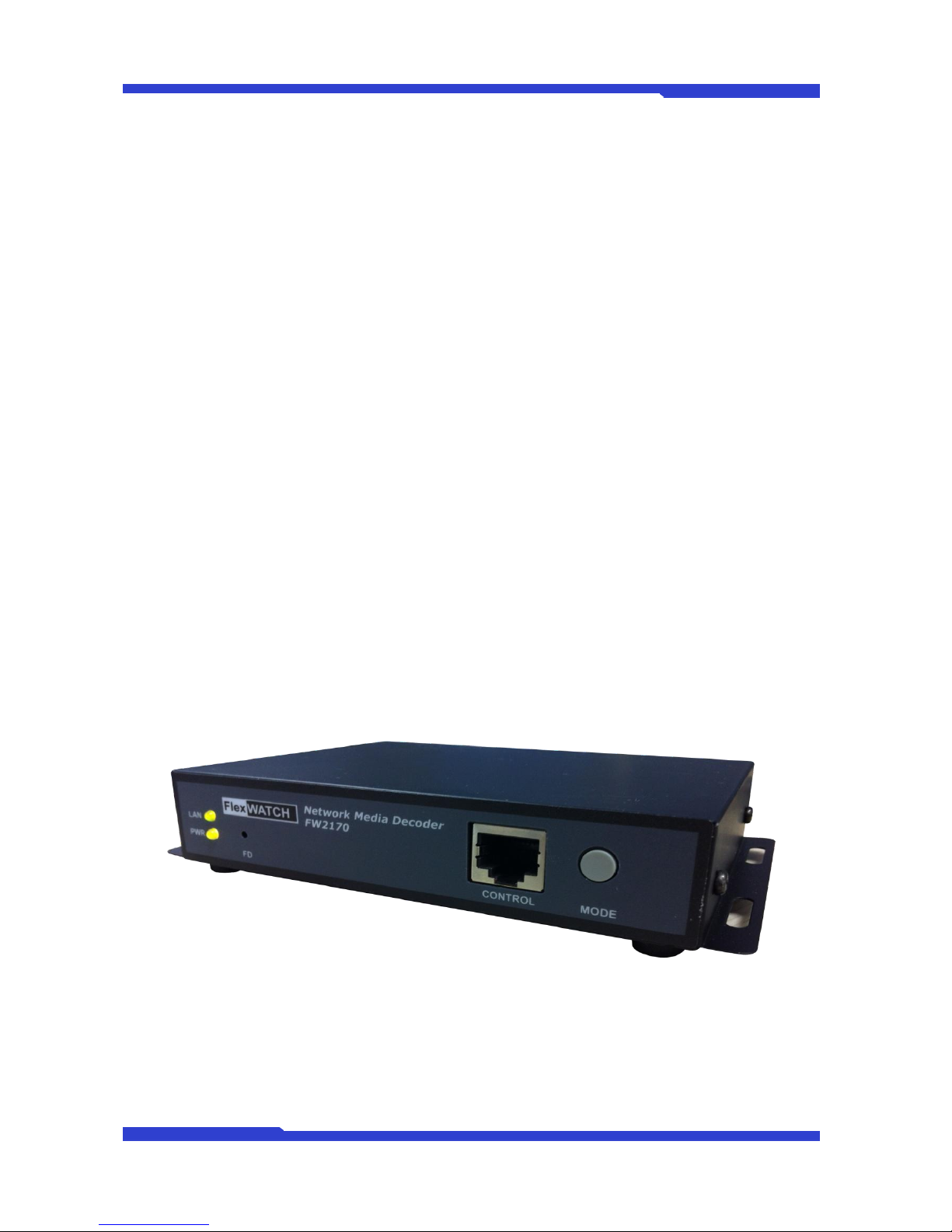
1.1. FW2170
FlexWATCH™ 2170 is a stand-alone 4ch network media decoder which converts four streams of
Motion JPEG or H. 264 from 4 different FlexWATCH™Video/Camera servers in real-time into the high
quality analog signals. It support 4 screens output and the FlexWATCH™Video/Camera input sources from
the encoder device
The server of FlexWATCH™ 2170 Network media decoder is used in combination with FlexWATCH™
video & camera servers. Users are able to use existing video matrices and other analog technology to
receive video and audio from distant analog cameras or systems
FlexWATCH™ 2170 is ideal package solution with FlexWATCH™cameras or servers for remote
monitoring using TV sets and Analog monitors. Also, instead of these multi channeled servers, you can use
single channel servers together. Thus, if you install cameras in remote site, you can watch the remote site
using video server and FlexWATCH® 2170 even though it might be located in a different city.
Picture 1 : FW2170

FW2170 User’s Manual
M4067-00 6 Seyeon Tech Co., Ltd
1.2. Key Features
Decodes network video without the need of a PC
Provides four channels of video up to 30fps decoding 1.3M per each channel.
Single Serial interface for Voice kit. Two way voice communication will be supported by software
upgrade later.
Single RS-485, RS-232 interface for future use. It can be used for Pan Tilt Zoom device control
using controller.
Supports dynamic IP at remote site using IPCCTVDNS.
Built-in Web server for administration.
Advanced alarm notification and service
When sensor or motion is triggered at FlexWATCH™2170 Network media decoder invokes the
4ch Rotation view immediately and displays the alarm status.
Factory Default Button for system initialization.

FW2170 User’s Manual
M4067-00 7 Seyeon Tech Co., Ltd
1.3. Preliminary Specification
Model
FW2170-DB
System
CPU
32bit Embedded Processor
OS
Embedded Linux
Flash
128M Byte
SDRAM
128M Byte
Video
Output
HDMI : HDMI Connector
Component : RCA Connector
Composite : BNC Connector
Input
M-JPEG, H.264 IP stream ( JES format stream only )
Decoding
Performance
Max
resolution
1.3M, @1024P
Max Rate
30 fps@1024p
Interoperable Devices
FlexWATCH®-IP Camera/NVS/NVR
( FW-1xxx / 3xxx/ 5xxx series )
Audio
Codec
1ch in & 1ch out, Mono Audio
8 bit PCM (G.711-u-low), Sampling rates 8KHz, Bandwidth: 8KByte/sec
Min/Max Audio Freq.: 300Hz ~ 3.4KHz
Network Protocol
HTTP, RTP/RTSP, TCP/IP, FTP, Telnet, RARP, PPPoE, PAP, CHAP,
DHCP, SMTP client(e- mail), NTP
Network I/F
LAN
10/100BaseT Ethernet auto sensing
Serial I/F
RS-232
RS-485
COM : console, serial input/output
RS-485 : joystick or Transparent mode
Alarm I/F
DI/DO
1 Photo-coupled Input and 1 Relay Output
Management
Web based configuration / Control
Web based upgrade
Function ( reserved )
Multi-Channel Circulation
Various Display Mode Selection by Push Button
Alarm / Status display
Operating Condition
Temperature -5℃~ +50℃, humidity 20~80% ( non-condensing )
Power
DC 12V/1A [SMPS], max power consumption ( DC12V, 600mA )
Certification
FCC / CE / KCC
Dimension(WXDXH) /
Weight
148(W)X118(D)X25(H) mm / about 0.25 Kg
* All specifications are subject to change without prior notice.
Table 1 : Specification for FW2170
FW2170 User’s Manual
M4067-00 8 Seyeon Tech Co., Ltd
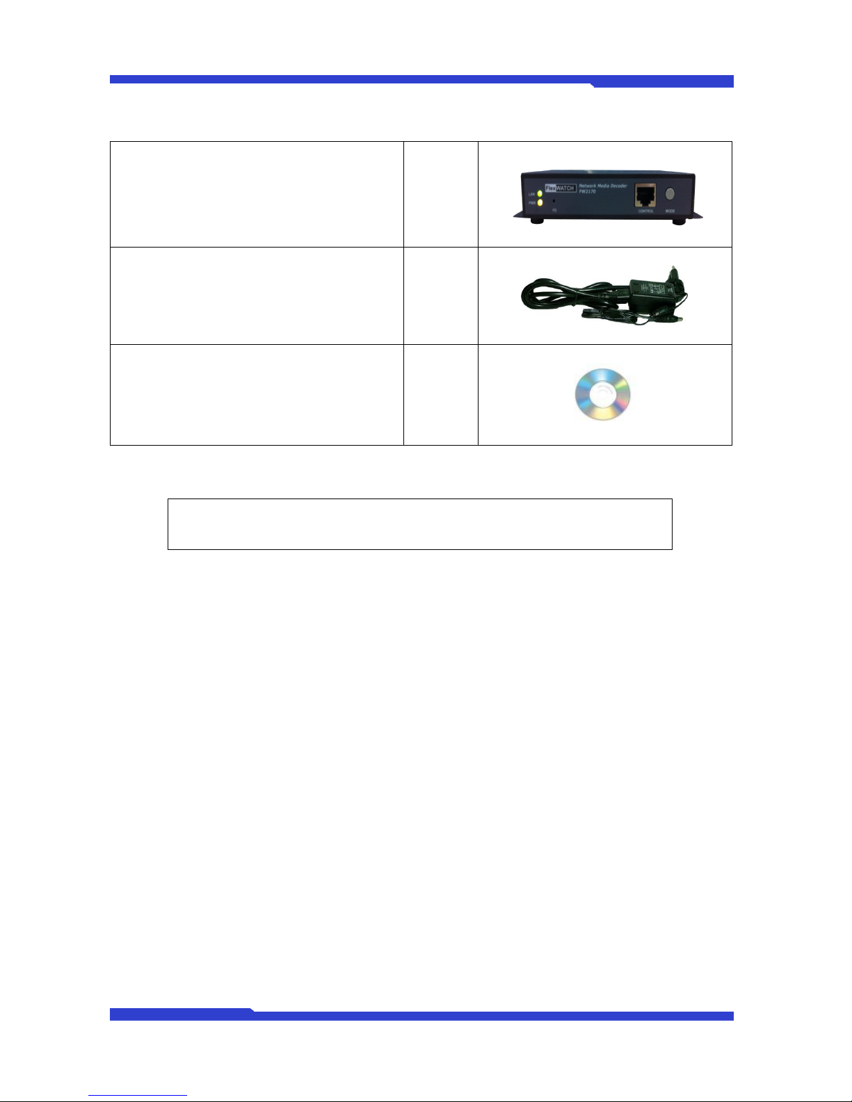
1.4. FW2170 Packing List
FW-2170
1ea
Power Supply Unit
(Power Cable & SMPS DC12V 1A Adapter)
1ea
CD (User’s Manual, installation wizard and
Pictures)
1 ea
Table 2 : FW2170 Packing List
Note: Please check all the listed items are included in your package. For any missing items,
please contact your local distributor.
FW2170 User’s Manual
M4067-00 9 Seyeon Tech Co., Ltd
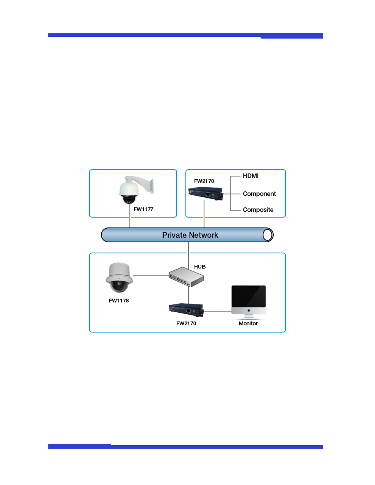
1.5. Network Diagram
FW2170 works over IP network such as leased line, cable model, XDSL modem, PSTN modem. FW-
2170 can also works over public network or private network. The network environment will vary with users’
goals and needs; however, basic applications with FW2170 can be as below.
1.5.1. Private Network
Private network without Internet connection.
1.5.2. Wide Area Network
FW2170 is able to decode Video stream Over IP network by IP Address and domain name, and AOIP
Service. Once FW2170 is assigned Dynamic IP Address, it is possible to decode Video stream from Wide
Area Network.

FW2170 User’s Manual
M4067-00 10 Seyeon Tech Co., Ltd
1.5.3. FW-2170 with the existing Analog System
FW2170 decode and transmits Video stream to analog system so that it an can be applied with Video
Matrix.

FW2170 User’s Manual
M4067-00 11 Seyeon Tech Co., Ltd
1.6. Application
FW2170 is born to provide reliable and flexible TCP IP network in the remote video surveillance
industry. Decoded Video stream by FW2170 can be monitored on standard TV or Audio/Video Devices.
Users easily monitor, search, and save Video stream by FlexWATCHTM server and FW2170 efficiently.
By combining with FlexWATCHTM server series, following can be suggested application area.
Chain store, and Franchised restaurant monitoring
Remote branch office monitoring
Plant, Oil refinery, Power station monitoring
Globally presented branch office monitoring
Parking Lots, Gas Station monitoring
FW2170 User’s Manual
M4067-00 12 Seyeon Tech Co., Ltd
2. Hardware Description
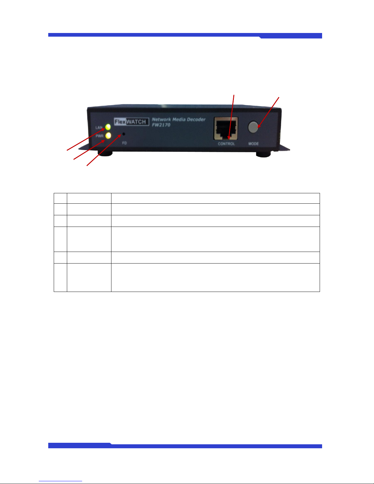
2.1. Front View
Picture 2 : FW2170 Front View
Name
Description
A
LAN LINK LED
Green light blinks when LAN is physically connected
B
Power LED
Red light blinks when power is provided
C
Factory Default
Button
This button can reset the factory default settings at the system.
Keep pressing FD button for about 5 seconds, after reboot the system. While pressing
this button, ACT LED is flickering.
D
CONTROL
CTL Port (RS-485, RS-232, DI, DO)
E
Display Mode
Switch
This button changes Display Mode. As you press the button, the Display Mode will be
changed one by one from Channel 1 to Channel 4. If you press the button for 2 sec., you
can apply Rotation Mode directly.
Table 3 : FW2170 Front View
D
E
A
B
C
FW2170 User’s Manual
M4067-00 13 Seyeon Tech Co., Ltd
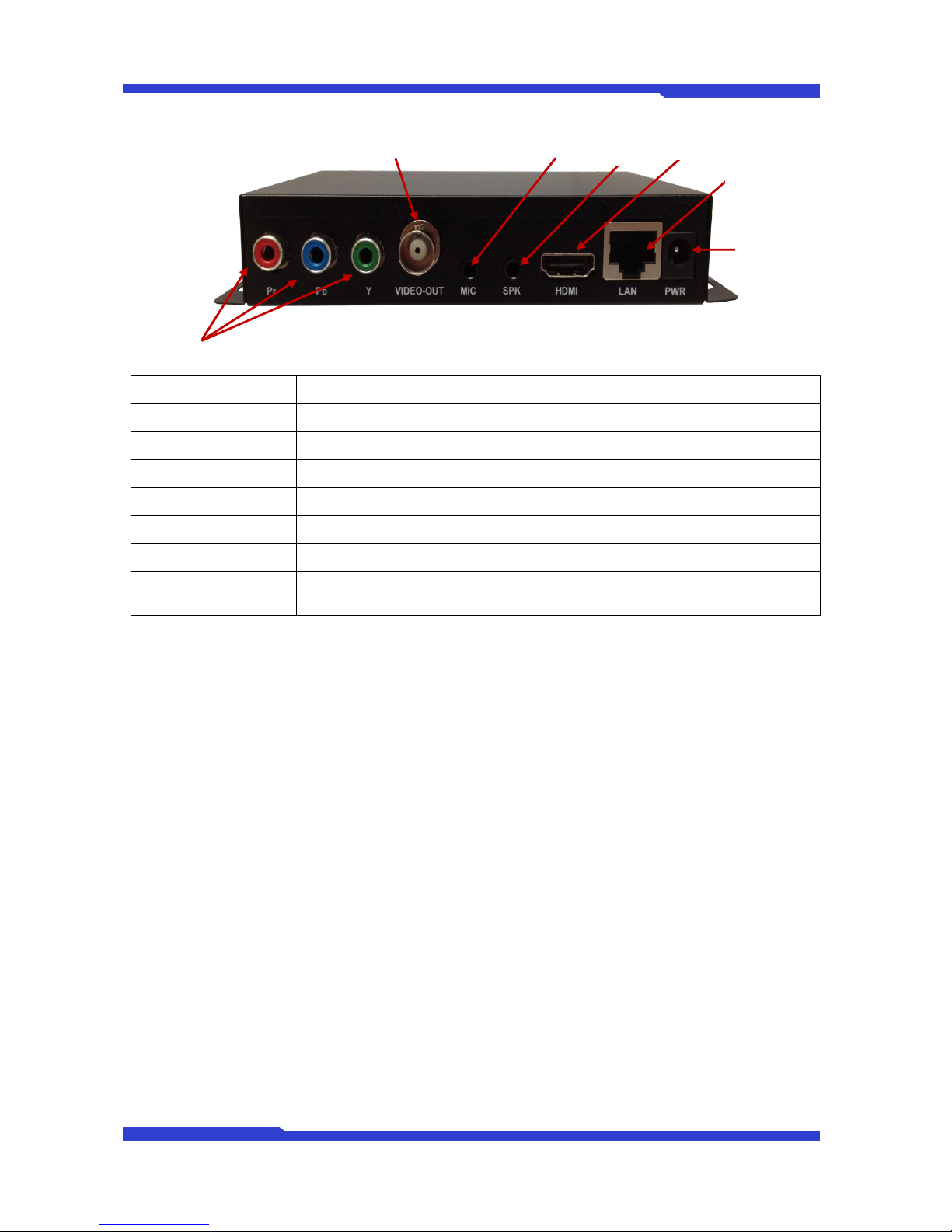
2.2. Rear View
Picture 3 : FW2170 Rear View
Name
Description
A
Component
Component Port
B
V-OUT
Composite Port (Video Output Port)
C
MIC
Audio Input Port
D
SPK
Audio Output Port
E
HDMI
HDMI Port
F
LAN
LAN Connector (10/100BaseT Ethernet auto sensing)
G
POWER ON/OFF
Power (DC 12V/1A [SMPS])
Table 4 : FW2170 Rear View
A
F
G
E
D
C
B
FW2170 User’s Manual
M4067-00 14 Seyeon Tech Co., Ltd
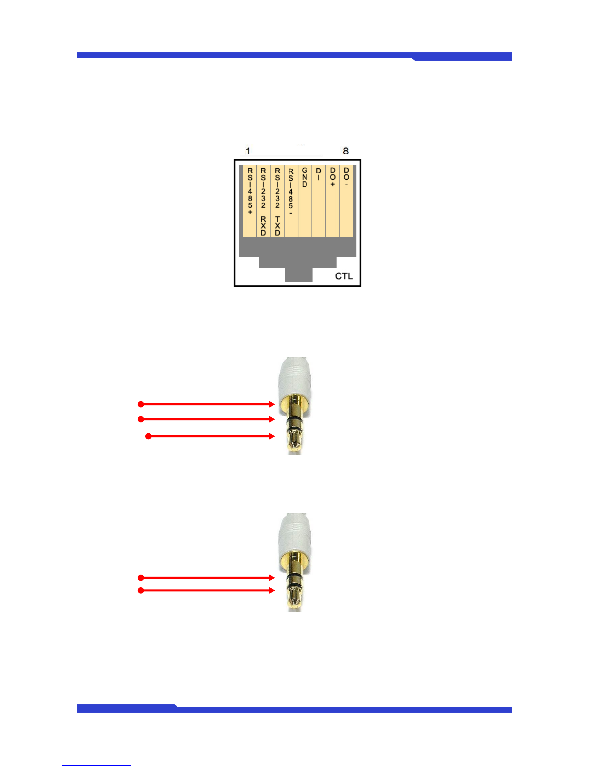
2.2.1. CTL Port Description
It’s RS-232 port for Serial input device, Modem or Console (Hyperterminal.connection). For RS-232
connection, RXD, TXD and GND are used. For connection to PC, RXD and TXD are used. RXD and TXD
should be cross to communicate properly
Picture 4 : CTL Port Description
2.2.2. Speaker V-out Jack Description
Jack information for Mono Speaker or Video Out Jack.
1 : GND
2 : SPK
3 : V-OUT
Picture 5 : V-out Jack
2.2.3. MIC Jack Description
Jack information for MIC
1 : GND
2 : NC
Picture 6 : MIC Jack

FW2170 User’s Manual
M4067-00 15 Seyeon Tech Co., Ltd
3. FW2170 Installation and Basic Setup
3.1. Before Installation
Read carefully User's Manual.
Check User’s Network (IP Address, Network Mask and default gateway)
Secure IP address for FW2170.
3.2. Factory Default Settings
The following table shows the factory default condition. Please refer to this when you need to change
the values on admin menu.
Factory Default
Admin ID
root
Admin password
root
IP address
10.20.30.40
Network mask
255.255.255.0
Gateway
10.20.30.1
Table 5 : Factory Default
Note: Factory default Admin ID and Password are all lower case letters. You can change the
password with Capital letters.
3.3. Installing FW2170
Following steps are the physical installation process for FW2170.
1. Fix the FW2170 in place
2. Connect the FW2170 to the Internet cable through the LAN port.
3. Connect the power supply of FW2170.
After that, you need to follow the steps below.
Network Configuration: Refer to “IP Installer User’s Manual”
Camera Configuration: Refer to “FlexWATCH™Admin Menu User’s Manual”
Service Configuration: Refer to “FlexWATCH™Admin Menu User’s Manual”
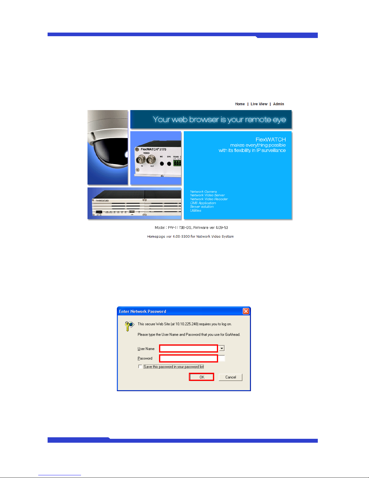
3.4 Network Configuration
1) Run Internet Explorer and input IP address of FW2170. You will see log in window as below.
FW2170 User’s Manual
M4067-00 16 Seyeon Tech Co., Ltd
Input ID and Password of Admin. (Default ID : root / Default Password: root)
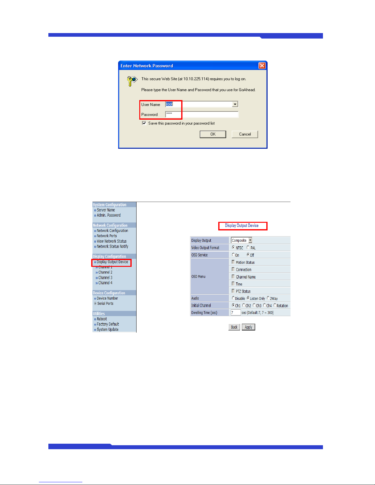
2) If you succeed in connecting to FW2170 Network Decoder System, “Display Output Device”
menu will be shown on the right side immediately and whole menus on the left side.
Because, you mainly need this menu “Display Output Device” while using FW2170.
FW2170 User’s Manual
M4067-00 17 Seyeon Tech Co., Ltd
4. Admin Menu
After connecting to a FlexWATCH™server on the web browser, you’ll find the web page as shown
below. The rightmost item of the menu is Admin, where you can set up the most of features in the
FlexWATCH™Server you’re connecting to.
4.1. Entering Admin Menu
Click “Admin” item of the menu, then you’ll see a login window. In the login window, enter “root” for
both ID and password as they are the factory defaults. Press Enter key or click “OK” button. Once logged in,
you can change the password to a new one.
Now the Admin Menu will be displayed as shown below. This will guide you to the top level menu
items, which are System, Network, Display, Device and Utilities. Clicking any of these top level menu items
will display submenu items and brief descriptions.
FW2170 User’s Manual
M4067-00 18 Seyeon Tech Co., Ltd
4.2. Admin Menu Structure
The following table shows the hierarchy of the Admin menu structure that we’re going to deal with in
this manual.
Category
Main Menu
Level 1 Sub-Menu
Level 2 Sub-Menu
System
configuration
Server Name
n/a
n/a
Admin. Password
Network
Configuration
Network Configuration
n/a
n/a
Network Ports
View Network Status
Network Status Notify
Display
Configuration
Display Output Device
Channel 1
n/a
Channel 2
Channel 3
Channel 4
Device Configuration
Device Number
n/a
n/a
Serial Ports
Transparent Mode
n/a
Utilities
Reboot
n/a
n/a
Factory Default
n/a
n/a
System Update
n/a
n/a
5. System Configuration Menu
When you click on “System Configuration”item on Admin Menu, the following sub menu will be
displayed.
FW2170 User’s Manual
M4067-00 19 Seyeon Tech Co., Ltd
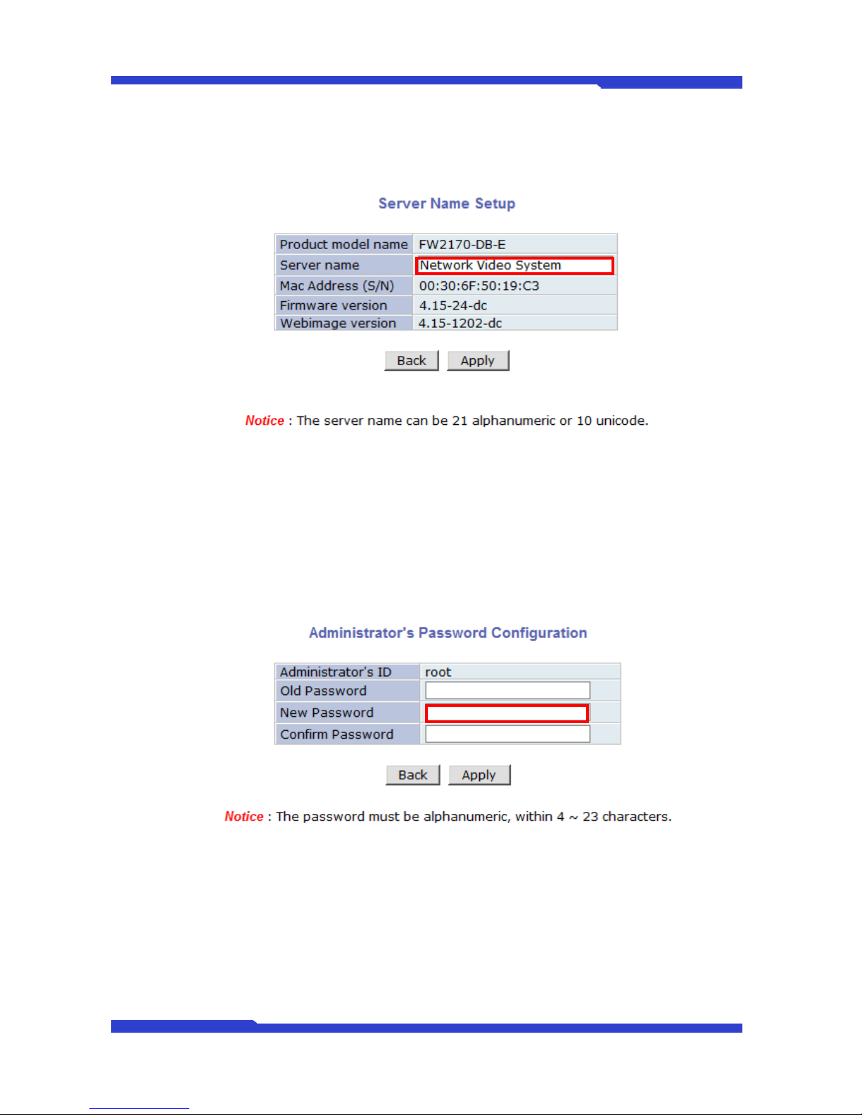
5.1. Server Name Setup
Click Step 1 on Quick Configuration, then the following will be displayed and you will find out the
system information such as model name of the FlexWATCH™Server, server name, MAC address (serial
number), firmware version, and Web image version.
As an administrator, you can change the name of the server name, but other values are not allowed to
change. To change the server name, enter a new server name in the Server Name filed. You may use up to
21 alphanumeric or up to 10 Unicode characters. Tab or any other special characters are not allowed. Click
“Apply” button to save the setting and it will take effect immediately.
5.2. Admin Password
To change the password for the administrator, click Admin Password on System Configuration menu.
Default ID for admin account is fixed as “root”and not allowed to change. In Old Password field,
enter the current password. In both New Password and Confirm Password fields, enter the same new
password. The password must be between 4 and 23 alphanumeric letters. Click “Apply” button to put it into
effect.
Because you have replaced the password with a new one, the existing network connection made with
old password to FlexWATCH™Server is lost now. You will have to reconnect to the FlexWATCH™server
using new password.

FW2170 User’s Manual
M4067-00 20 Seyeon Tech Co., Ltd
6. Network Configuration
Configuration the network is dependent on how an IP address is assigned in Ethernet-based
environment, which is static IP, dynamic IP (DHCP). For wireless LAN, additional configuration is necessary
to have a connection with wireless AP.
In the case of wireless models, users have to choose between wired or wireless connection. In other
words, both connections can’t be used at the same time. The way how to choose one of them is whether
wired LAN cable is plugged into the product. When LAN cable is plugged in for longer than 5 seconds, the
wired LAN is activated for data transmission. If LAN cable is unplugged more than 5secconds, wireless LAN
is activated instead. If DHCP Client is selected by user, wired LAN will be activated regardless of condition of
LAN cable. For network configuration, select Network configuration from Admin page.
To make a connection to the Internet, it is required to figure out the type of the Internet service you’re
using. Depending on the service type, the network configuration can be in any of Static IP, DHCP Client.
You need to set up the FlexWATCH™Server according to your network type.
6.1. Network Configuration
6.1.1. Static IP Configuration
Selecting Network Configuration under Network configuration will show variables. Below picture is for
products without wireless LAN.
For static IP, select static IP and input values for IP address, NetMask, Gateway, DNS1, DNS2 and
Table of contents
Popular Media Converter manuals by other brands

OpenVox
OpenVox PFM100 user manual

Teryair
Teryair SC29PG Operation & maintenance guide

Cypress
Cypress SY-P290 Operation manual

Omnitron Systems Technology
Omnitron Systems Technology OmniConverter GPoE+/SX user manual

McIntosh
McIntosh MDA1000 Service manual

TBS technologies
TBS technologies TBS2614 user manual


