NCE Switch-It User manual

Switch-It
Accessory Decoder
FOR STALL MOTOR SWITCH MACHINES ONLY
NOT FOR USE WITH TWIN COIL SWITCH MACHINES
Dimensions: 2.1" x 1.3" (54 x 33 mm)
Decoder revision C
$19.95
Now with EASIER PROGRAMMING!
This is an accessory (switch machine) decoder
‚Control for two TortoiseTM switch machines
‚Switch-It remembers the position of switch during power outages
‚Switch-It supports the full range of DCC accessory addresses (1-2044)
‚Easy address programming, no need to connect it to programming track
‚Each switch machine can have its own completely different address
‚Simple hook up, 2 wires to the track, 2 wires to each switch machine
‚Includes optional connections for "local" control push buttons
‚Also operates on non-DCC layouts
Every attempt has been made to ensure this decoder complies with all
applicable NMRA Standards and Recommended Practices
This book, schematics and artwork copyright 1998-2007
NCE Corporation 899 Ridge Road Webster, NY 14580
Switch-It is a trademark of NCE Corporation
Last revised: 15 March 2007

Installation Notes:
This decoder is designed to control Tortoise, SwitchMaster or other low current "stall
motor" switch machines. The outputs are rated for 50mA maximum. Most Tortoise
machines draw 20 to 25mA with normal track voltage (about 13-15 volts). We use
double sided foam tape to mount the Switch-It to the side of a Tortoise.
Wiring:
See the diagram below for wiring particulars. The only required wires are two wires to
the track and two wires to each machine. It is OK to use the Switch-It for control of only
one machine.
Optional push buttons:
Push buttons may be added for local control of the switches. Buttons 1 and 2 control
switch "A" and buttons 3 and 4 control switch "B". Use momentary contact switches
for local control. Do not use a toggle switch (unless it is momentary), its continuous
connection will prevent DCC control of the turnout. In the illustration above the push
button terminals filled in with black are "common" with each other. Buttons 1 and 2 are
shown wired with a common wire to each push button as are buttons 3 and 4. It is OK
to use only one common wire for all 4 push buttons. You can have multiple buttons
wired in parallel for operation of the machine from more than one control panel. If the
Switch-It is used on DC (12-16 volts DC) the buttons will still work.
You can also program the Switch-It to “toggle” the outputs with each push of the local
control pushbuttons. Button 1 will control the SWA output and button 4 will control the
SWB output. Buttons 2 and 3 will be ignored and are not needed.
Switch machine mounting tip:
On our Tortoise machines we use hot glue to mount the machine. The glue stays
liquid just long enough after application to allow alignment of the machine. We
manually center the arm of the machine then slide the machine around while the glue
sets to align the points to the middle of their throw. The low temperature hot glue is
weak enough to allow removal of the machine later on by prying with a putty knife.
Use a throw wire that is about 6” (150mm) longer than the one provided with the
Tortoise to give you room to put glue on the machine after the wire is put through the
roadbed.
Last revised: 15 March 2007 Page2
TRK SWA SWB
1234
NCE SWITCH-IT REV C
To Track
SWITCH
MACHINE
"A"
SWITCH
MACHINE
"B"
"Local" control push buttons
can be mounted on fascia,
control or dispatcher panels
OPTIONAL
Tortoise Machines
Illustrated above
SWITCH-IT wiring diagram
4
3
2
1
Do not connect decoder common
to the common of other Switch-Its
PB
PA

Programming information
The Switch-It cannot be programmed on your programming track. It is always
programmed while connected to the mainline track. This decoder can be programmed
by all systems that support accessory control using the procedure below.
To program switch "A" to a new address using any DCC system:
1) Connect wires from the track to the decoder TRK connections.
2) Connect a short "jumper" wire from the PA terminal to common as shown below.
3) Use your DCC system to throw the accessory (switch) number you want the
Switch-It to use as its new address.
To throw a switch using the NCE or MRC system:
Press “SEL ACCY”
Type in the accessory number followed by “ENTER”
Push “1” to throw the switch.
To throw a switch using a Digitrax system:
Press “SWCH”
Type in the accessory number
Push “OPTN” to throw the switch.
To throw a switch using a Lenz system:
Press “F”
Press “5”
Type in the accessory number followed by “ENTER”
Push “+”
4) Remove the jumper wire.
Do not leave the jumper in place after programming or you won’t be able to
control the switch.
To program switch "B" to a new address using any DCC system:
1) Connect wires from the track to the decoder TRK connections.
2) Connect a short "jumper" wire from the PB terminal to common as shown below.
3) Use your DCC system to control the accessory (switch) number you wish the
decoder to use as its address for the SWB output. (see step 3 above)
4) Remove the jumper wire.
Do not leave the jumper in place after programming or you will not be able to
control the switch.
Last revised: 15 March 2007 Page3
"Jumper" wire
to program SWA
TO TRACK "Jumper" wire
to program SWB
Install only ONE jumper at a time when programming accessory addresses
TRK SWA SWB
1234
NCE SWITCH-IT REV C
RST
PA PB

Set pushbutton 1 to "toggle" the SWA output (disables pushbutton 2):
NCE Power ProTM or PowerCabTM users can use the PROG ACCESSORIES
feature of your system. Set CV548 = 1 (use the accessory address of SWA) to
enable the ‘toggle’ option or set CV548 = 0 to disable it.
If you have another brand of DCC system use the following procedure:
1) Disconnect track power to the Switch-It.
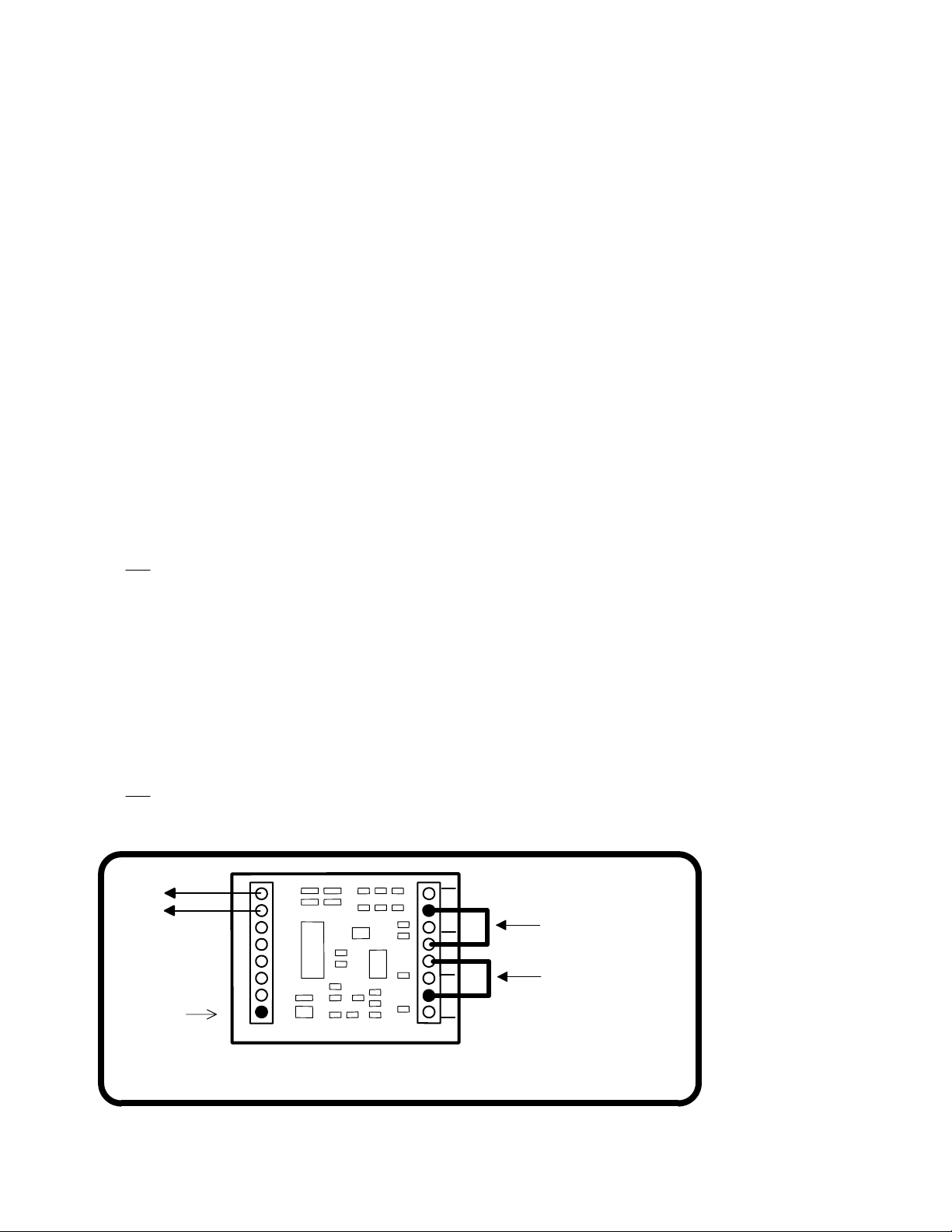
2) Connect PA to the right hand RST terminal indicated by the arrow in the above
figure.
3) Reconnect track power to the Switch-It
4) Remove the PA to RST jumper
Set pushbutton 4 to "toggle" the SWB output (disables pushbutton 3):
NCE Power ProTM or PowerCabTM users can use the PROG ACCESSORIES
feature of your system. Set CV549 = 1 (use the accessory address of SWB) to
enable the ‘toggle’ option or set CV549 = 0 to disable it.
If you have another brand of DCC system use the following procedure:
1) Disconnect track power to the Switch-It.
2) Connect PB to the right hand RST terminal indicated by the arrow in the above
figure.
3) Reconnect track power to the Switch-It
4) Remove the PB to RST jumper
To set the Switch-It to "exercise" the switch points at each power up:
NCE Power ProTM or PowerCabTM users can use the PROG ACCESSORIES
feature of your system. Set CV547 = 1 (use the accessory address of SWA) to
enable the ‘exercise’ option or set CV547 = 0 to disable it.
If you have another brand of DCC system consult your manual for programming of
accessories in Operations mode.
Legacy OPS programming disable (CV554):
There are two methods for programming accessory decoders “on the main” (OPS
mode programming). Legacy mode, in use since 1995, is being phased out by the
NMRA and replaced by the current, newer method. The Switch-It supports both
kinds of programming on the main.
NCE Power ProTM or PowerCabTM users can use the PROG ACCESSORIES
feature of your system. Disable Legacy mode by setting CV554 to a value of 1. If
you disable legacy mode and find you can no longer program the decoder with your
system, your system only supports legacy mode. You can re-enable Legacy mode
by resetting the Switch-It back to factory defaults as described below.
If you have another brand of DCC system consult your manual for programming of
accessories in Operations mode.
Pushbutton lockout (CV556):
On some layouts it may be desirable to disable operation of the local control
pushbuttons. NCE Power ProTM or PowerCabTM users can use the PROG
ACCESSORIES feature of your system.
Set CV556 = 1 to disable the optional pushbutton inputs. CV556 = 0 enables the
buttons.
You can disable or enable ALL decoders on the layout at the same time by using
the accessory decoder broadcast address of 2044 when programming CV556.
If you have another brand of DCC system consult your manual for programming of
accessories in Operations mode.
Last revised: 15 March 2007 Page4

Factory reset:
Momentarily connecting the two RST terminals will reset the decoder to the original
factory settings as indicated below
.
Factory default values for decoder
Output SWA is factory programmed to accessory address 1 (decoder addr 1, output 1)
Output SWB is factory programmed to accessory address 2 (decoder addr 1, output 2)
CV547 is set to 0 (Power up exercising of switch machine disabled)
CV548 is set to 0 (use pushbutton 1 to “toggle” output SWA, pushbutton 2 is disabled)
CV549 is set to 0 (use pushbutton 4 to “toggle” output SWB, pushbutton 3 is disabled)
CV554 is set to 0 (legacy accessory OPS programming enabled)
CV556 is set to 0 (pushbutton lockout is disabled)
Other technical stuff:
vWe have successfully controlled two Tortoise switch machines with one decoder
output when used in a crossover. We can't guarantee this will work in all cases.
vThe outputs of the decoder are always on to prevent the switch machine from backing
off due to the springiness of the turnout throw mechanism.
vIf CV547 is programmed to 1 (“exercise” enabled) the decoder will "back off" the
switch (usually about halfway) then return the switch to its remembered position at
power up. This is to make sure the points are fully thrown (solves sticky point
problems).
vSee the diagram below for turnout position indicator light wiring. LEDs are wired in
series with the switch machine to indicate which position the turnout is thrown. Most
LEDs will handle up to 25mA, the switch motor acts as the current limiting device for
the LEDs. We use red and green LEDs but any color will do. The switch machine will
run a bit slower with LEDs installed due to about a 1.5 volt loss in the LED.
Last revised: 15 March 2007 Page5
TRK SWA SWB
RED
GREEN
LEDs
Tortoise
Machine
Shown

TIP:
If you use power routing turnouts such as Peco Electro-Frog, Shinohara or Walthers
we suggest wiring a #1156 automotive taillight bulb in series with the points of the
turnout (see above). This will prevent short circuits from shutting down your power
booster in the event you enter the turnout from the frog end without aligning the points.
Warning: This product contains chemicals known to the State of
California to cause cancer, birth defects or other reproductive harm.
Warranty
This decoder is fully factory tested and warranted against manufacturing defects for a
period of 1 year. As the circumstances under which this decoder is installed can not be
controlled, failure of the decoder due to installation problems can not be warranted. This
includes misuse, miswiring, operation under loads beyond the design range of the
decoder or short circuits in the locomotive manufacturer’s factory wiring. The warranty is
voided if the decoder is miswired, connected to more than 22 volts, or used with switch
motors drawing more than 40mA.
If the decoder fails for non-warranted reasons NCE will replace the decoder, no questions
asked, for $10 US plus $2 shipping. For warranty or non-warranty replacement send the
decoder (an any payment, if required) to:
NCE Warranty Center 899 Ridge Road Webster, New York 14580
05240114
05240114
The terms Silent Running, Power Pro, PowerCab , ProCab, Switch-It, Snap-It, the NCE logo with “Power of DCC” slogan are
trademarks of NCE Corporation. Digitrax is a trademark of Digitrax Inc. Tortoise is a trademark of Circuitron, Inc. MRC is a
trademark of MRC Corporation. The distinctive shape of the ProCab when used with a thumbwheel speed control and LCD
display is a trademark of NCE Corporation.
Last revised: 15 March 2007 Page6
#1156
Bulb
Tortoise
Machine
Shown
Table of contents
Other NCE Media Converter manuals
Popular Media Converter manuals by other brands

Baumer
Baumer HUBNER BERLIN HOG 10 Mounting and operating instructions

Assun
Assun AM-EN2412-T003 Series product manual

Extron electronics
Extron electronics Two InpuT VIdeo Scaler IN1502 user manual

CommFront
CommFront USB-232-1+TTL33-232-1 manual

Ikan
Ikan HDMI-SDI-01 quick start guide

Atek
Atek ARF S 58 user manual