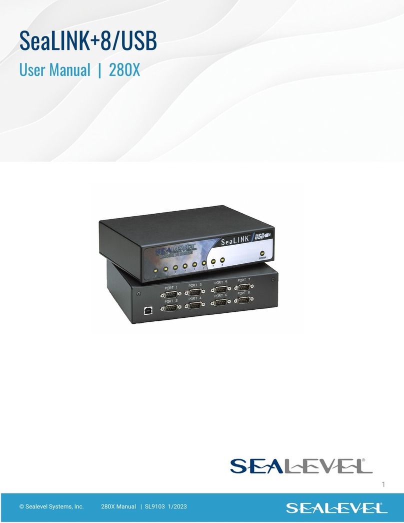
Sferalabs Iono Pi User manual

"
Iono Pi Board Quick Reference
May 2017
Revision 002
Board version 1.2
www.sferalabs.cc#
Page of 1 6

Be sure to always remove the power supply before connecting or
disconnecting the Iono Pi board to Raspberry Pi.
In order to meet the relevant CE requirements, Iono Pi must be operated
fully enclosed in its DIN-rail case.
Follow all applicable electrical safety standards, guidelines,
specifications and regulations for installation, wiring and operations of
Iono Pi.
Carefully read the complete Iono Pi User Guide before installation.
Iono Pi is not authorised for use in safety-critical applications where a failure of the product
would reasonably be expected to cause personal injury or death. Safety-critical
applications include, without limitation, life support devices and systems, equipment or
systems for the operation of nuclear facilities and weapons systems. Iono is neither
designed nor intended for use in critical military or aerospace applications or environments
and for automotive applications or environment. Customer acknowledges and agrees that
any such use of Iono Pi is solely at Customer's risk, and that Customer is solely
responsible for compliance with all legal and regulatory requirements in connection with
such use.
Sfera Labs S.r.l. may make changes to specifications and product descriptions at any time,
without notice. The product information on the web site or materials is subject to change
without notice.
Please download and read the Terms and Conditions document available at:
http://www.sferalabs.cc
Iono and Sfera Labs are trademarks of Sfera Labs S.r.l. Other brands and names may be
claimed as the property of others.
"
Copyright © 2015-2017 Sfera Labs S.r.l. All rights reserved.
Page of 2 6

SPECIFICATIONS
Power supply
9÷28V⎓(VDC)
Reverse polarity protection with 1.1A resettable
fuse. Surge protection up to ±500V/2ohms 1.2/50μs
Current consumption at VS+=12V⎓
including Raspberry Pi 3 current, no USB devices
connected
Low CPU/GPU load:
•135mA unconnected inputs, relays OFF
•225mA inputs connected to VSOUT, relays ON
High CPU/GPU load:
•340mA unconnected inputs, relays OFF
•430mA inputs connected to VSOUT, relays ON "
Actual current consumption may vary based on
working conditions
Current consumption at VS+=24V⎓
including Raspberry Pi 3 current, no USB devices
connected
Low CPU/GPU load:
•75mA unconnected inputs, relays OFF
•135mA inputs connected to VSOUT, relays ON
High CPU/GPU load:
•170mA unconnected inputs, relays OFF
•225mA inputs connected to VSOUT, relays ON "
Actual current consumption may vary based on
working conditions
Maximum available power supply current to Pi board
2.5A
Raspberry platform compatibility
Pi 3 Model B
Pi 2 Model B
Voltage range at digital inputs
DI1..DI3: 0÷40V ⎓in normal mode;
0÷5V ⎓in TTL mode"
DI4..DI6: 0÷40V ⎓
Current for each digital input in normal mode
DI1..DI3:
•1.7mA at VS+=12V ⎓
•3.4mA at VS+=24V ⎓"
DI4..DI6:
•1.9mA at VS+=12V ⎓
•3.9mA at VS+=24V ⎓
Voltage threshold digital inputs in normal mode
•VIH: 4.2V
•VIL: 3.4V
Voltage threshold digital inputs in TTL mode
•VIH: 2.4 V
•VIL: 0.8 V
Range for analog inputs
•AI1..AI2: 0÷30V ⎓
•AI3..AI4: 0÷3V ⎓
Impedance for analog inputs
AI1..AI4: 200kOhm
Page of 3 6

Analog inputs characteristics
•Resolution: 12 bits
•Linearity: ±1LSB
•MAX error: ±2% of full scale
Maximum recommended cable length for digital
inputs
•normal mode: 30m
•TTL mode: 2m
Maximum recommended cable length for analog
inputs 1-2
15m
Maximum recommended cable length for open
collector outputs
2m
Maximum output contact rating (each output)
•Resistive load (cos φ= 1): 6A at 250V~ (1500VA)
•Inductive load (cos φ= 0.5): 1A at 250V~ (250VA)
•Fluorescent lamps:150W with 20uF MAX power
factor correction capacitor
•Resistive load (DC1): 1A at 48Vdc / 0.7A at 60Vdc
Open collector outputs rating
NPN type, shared with DI4..DI6, common on
VSOUT, short circuit protected"
100mA MAX output current
AUX VSOUT
•Max allowable current: 300mA
•Min voltage: Supply voltage – 1V
AUX 5VOUT
•Max allowable current: 50mA
•Min voltage: 4.5V
Real time clock
Internal RTCC circuit with back-up Lithium battery"
Expected battery life without main power supply:
~3%years
Expected battery life with main power supply:
>10%years
15-pin terminal block characteristics
Maximum conductor cross section: 1.5 mm2 (16
AWG), or 0.5 mm2 when using ferrules (highly
recommended)
Recommended stripping length: 5 mm
Screw thread: M2
Maximum screws tightening torque: 0.25 Nm
8-pin terminal block characteristics
Maximum conductor cross section: 2.5 mm2 (12
AWG)
Recommended stripping length: 7 mm
Screw thread: M3
Maximum screws tightening torque: 0.6 Nm
Housing
standard 4M for DIN rail
Operating temperature
0…+50 °C
Storage temperature
-20…+70 °C
Protection degree
IP20
Page of 4 6

Installation and use restrictions
(Applicable in the European Union and other European countries with separate
collection systems). This marking on the product, accessories or literature
indicates that the product should not be disposed of with other household
waste at the end of their working life. To prevent possible harm to the
environment or human health from uncontrolled waste disposal, please
separate these items from other types of waste and recycle them responsibly to promote
the sustainable reuse of material resources. Household users should contact either the
retailer where they purchased this product, or their local government office, for details of
where and how they can take these items for environmentally safe recycling. This product
and its electronic accessories should not be mixed with other commercial wastes for
disposal.
Iono Pi contains a small non rechargeable manganese dioxide lithium coin battery. This
cell battery contain so little lithium that it should not qualify as a reactive hazardous waste.
If you need to follow specific disposal procedures for the battery, it can be easily separated
from the circuit board by simply cutting its two terminals near the soldering points (paying
attention not to pinch or fracture the battery body).
Standards and regulations
The design and the setting up of electrical systems must be performed according to the
relevant standards, guidelines, specifications and regulations of the relevant country. The
installation, configuration and programming of the devices must be carried out by trained
personnel. The installation and wiring of connected devices must be performed according
to the recommendations of the manufacturers (reported on the specific data sheet of the
product) and according to the applicable standards. All the relevant safety regulations, e.g.
accident prevention regulations, law on technical work equipment, must also be observed.
Safety instructions
Protect the unit against moisture, dirt and any kind of damage during transport, storage
and operation. Do not operate the unit outside the specified technical data. Never open the
housing. If not otherwise specified, install in closed housing (e.g. distribution cabinet).
Earth the unit at the terminals provided, if existing, for this purpose. Do not obstruct cooling
of the units. Keep out of the reach of children.
Set-up
For the first installation of the device proceed according to the following procedure:
✓make sure all connections, including the power supply and any other external devices
are disconnected
✓install and wire the device according to the schematic diagrams on the specific data
sheet of the product
✓after completing the previous steps, switch on the power supply and other related
circuits.
Page of 5 6

Standards
✓2014/35/UE (Low Voltage)
✓2014/30/UE (EMC)
✓EN61000-6-2:2005 (EMC Immunity)
✓EN60664-1:2007 (Electrical safety)
✓EN61000-6-3:2007 (Emission)
✓2011/65/UE (RoHS).
WiFi and Bluetooth must be disabled on the Raspberry Pi 3 to meet the above CE
directives.
Hardware Installation
The Iono Pi board is supplied with all connectors pre-installed. No soldering is required.
You should connect Iono Pi to Raspberry Pi aligning the GPIO connector. Use appropriate
turrets/spacers to firmly bolt the two boards together, ensuring that no conductive part of
one board touches any part of the other board.
Be particularly careful to ensure there is enough clearance between the Ethernet and USB
connectors and the bottom of Iono Pi’s circuit board.
The Iono Pi board is compatible with Raspberry Pi 2 Model%B and Raspberry Pi 3 Model%B.
Installing boards that are not fully compatible, both mechanically or electrically, may and
probably will damage both Iono Pi and any other component connected to it, and may
create a safety risk.
The factory warranty does not cover any damage directly or indirectly caused by the
installation and removal of the Iono Pi board and Raspberry Pi.
Terminal block
Iono Pi has two terminal blocks: a 15 positions terminal block, used for power supply and
low-power input/output connections, and a 8 positions terminal block on the opposite side,
for the power relays outputs.
Power supply
Iono Pi can be powered with DC voltage only:
✓DC: nominal voltage range 9.0V to 28.0V.
Respect the correct polarity shown in the schematic diagram (+ -).
A blue on-board LED, also visible through the front panel of the DIN-rail case, is lit when
power supply is available.
When a Iono Pi board is used, never connect the Raspberry Pi micro-USB power plug.
Read the Iono Pi User Guide for detailed installation and use information related to the
auxiliary power supply output (VSOUT and 5VOUT).
Page of 6 6
Other manuals for Iono Pi
1
Table of contents
Other Sferalabs Computer Hardware manuals

