EVGA Z790 DARK K|NGP|N User manual

EVGA Z790 DARK K|NGP|N (121-RL-E799)
- 1 -
User Guide
EVGA Z790 DARK K|NGP|N
Specs and Initial Installation

EVGA Z790 DARK K|NGP|N (121-RL-E799)
- 2 -
Table of Contents
Before You Begin… .................................................................................................- 4 -
Parts NOT in the Kit............................................................................................................. - 5 -
Intentions of the Kit.............................................................................................................. - 5 -
Motherboard Specifications.................................................................................................. - 6 -
Unpacking and Parts Descriptions........................................................................................ - 8 -
EVGA Z790 DARK K|NGP|N Motherboard LED............................................................. - 10 -
EVGA Z790 DARK K|NGP|N Component Legend........................................................... - 14 -
PCIe Slot Breakdown ......................................................................................................... - 26 -
M.2 Slot Breakdown........................................................................................................... - 26 -
Preparing the Motherboard................................................................................................. - 27 -
Installing the CPU .............................................................................................................. - 27 -
Installing the CPU Cooling Device .................................................................................... - 28 -
Installing System Memory (DIMMs) ................................................................................. - 29 -
Installing the I/O Shield...................................................................................................... - 29 -
Installing the Motherboard......................................................................................- 30 -
Securing the Motherboard into a System Case................................................................... - 31 -
Installing M.2 Devices............................................................................................- 33 -
Installing M.2 Key-M Socket 3 Devices ............................................................................ - 33 -
Tested CPU......................................................................................................................... - 36 -
Tested M.2 Key-M ............................................................................................................. - 37 -
Tested M.2 Key-E............................................................................................................... - 38 -
Connecting Cables.............................................................................................................. - 39 -
Onboard and External Buttons............................................................................................ - 51 -
First Boot................................................................................................................- 52 -
M.2 SSD, PCIe SSD, and NVMe SSD Installation steps ................................................... - 54 -

EVGA Z790 DARK K|NGP|N (121-RL-E799)
- 3 -
Configuring RAID With M.2 SSDs.................................................................................... - 56 -
Internal SATA RAID Controller...............................................................................- 60 -
Fan Header DC and PWM setup ...........................................................................- 86 -
Installing Drivers and Software ............................................................................- 100 -
Windows 11/10 Driver Installation .................................................................................. - 100 -
Warranty and Overclocking.............................................................................................. - 102 -
Troubleshooting ...................................................................................................- 103 -
Flashing the BIOS ............................................................................................................ - 103 -
Flashing the BIOS Without a CPU................................................................................... - 105 -
SSD / HDD is not detected ............................................................................................... - 107 -
Using the POST code indicator to troubleshoot ............................................................... - 109 -
System does not POST and Multi-function Display reads “C” ........................................ - 109 -
System does not POST, and Multi-function Display reads “55” ...................................... - 110 -
System does not POST, and Multi-function Display reads “d7” ...................................... - 110 -
Have a question not covered above, or want some online resources? .............................. - 111 -
Multi-function Display POST Debug LED ...................................................................... - 112 -
Multi-function LED indicator........................................................................................... - 113 -
POST Beep codes............................................................................................................. - 115 -
POST Codes........................................................................................................- 116 -
EVGA Glossary of Terms ................................................................................................ - 121 -
Compliance Information.......................................................................................- 124 -

EVGA Z790 DARK K|NGP|N (121-RL-E799)
- 4 -
Before You Begin…
The EVGA Z790 DARK K|NGP|N rises once again. This world record-
setting motherboard is built on a 14-layer low-loss PCB with a 21-phase VRM –
capable of squeezing every last bit of performance out of the most extreme 13th
Gen Intel®Core™processors. This board supports current and future standards
with up to 64GB DDR5 and up to 8000MHz+(OC)*, PCIe Gen5, and PCIe
Gen4 M.2 NVMe support. The Z790 DARK K|NGP|N auto-switches the x16
PCIe Gen 5 CPU lanes between slots 1 and 2 to give your PCIe device
maximum bandwidth no matter where it’s installed**. Beyond excessive
overclocking support, the board also includes multiple USB options, 8x SATA
6Gb/s ports, Wi-Fi 6E / BT 5.2, and 3x M.2 Key-M slots. The Z790 DARK
K|NGP|N remains the choice of those that want a board capable of
unbelievable performance.
For its other features, the Z790 DARK K|NGP|N contains Realtek 7.1
Channel HD Audio, an Intel®2.5 GbE NIC, a Marvell 10 GbE NIC, onboard
power/reset/CMOS buttons, triple BIOS support, 8 smart fan headers
(including 2x pump headers exclusively built for CPU AIO), and many more
premium features. If you’ve been holding out for a serious motherboard, the
time is at hand.
Lastly, a motherboard is only as good as its BIOS, and the EVGA Z790 DARK
K|NGP|N features EVGA’s latest BIOS GUI with a focus on overclocking
and functionality in a lean, straightforward package. You won’t need to be an
expert to configure your motherboard, but if you are, you’ll find features
unavailable anywhere else.
*Achievable speeds may vary depending on memory configuration and CPU memory controller.
**x16 lane support if only one PCIe slot (PE1/PE2) is populated. x8/x8 lanes if both PE1 and PE2 are
populated.

EVGA Z790 DARK K|NGP|N (121-RL-E799)
- 5 -
Parts NOT in the Kit
Your EVGA Z790 DARK K|NGP|N package contains all the accessories
necessary to install and connect your new motherboard to the rest of your
hardware. However, the following items must be purchased separately in order
to make the system fully functional and ready to install an Operating System:
Intel®Socket 1700 Processor
DDR5 System Memory
CPU Cooling Device
PCI-Express Graphics Card
Power Supply
Hard Drive or SSD
Keyboard and Mouse
Display
(Optional) Optical Drive
EVGA assumes you have purchased all the necessary parts needed to allow for
proper system functionality. For a full list of compatible CPUs for this
motherboard, please visit https://www.evga.com/support/motherboard
Intentions of the Kit
This motherboard is designed to be the hub for most –if not all –of your PC
hardware components, and is therefore a critical component for your OS. If you
are upgrading or replacing another motherboard, it is recommended to start
with a fresh install of your OS.

EVGA Z790 DARK K|NGP|N (121-RL-E799)
- 6 -
Motherboard Specifications
Form-Factor: E-ATX - 11.99 inches x 10.89 inches (304.5mm x 276.6mm)
Microprocessor support:
Intel®Socket 1700 Processors (Raptor Lake-S and Alder Lake-S)
Operating Systems:
Supports Windows 11, Windows 10 64bit
System Memory support:
Supports up to 64GB Dual-Channel DDR5
Supports up to 8000MHz+ (OC) Dual-Channel DDR5
- Achievable speeds depend upon configuration and CPU memory controller
USB 2.0 Ports:
4x from Intel®Z790 PCH –4x internal via 2 FP headers
1x from Update Port for flashing the BIOS without CPU
USB 3.2 Gen1 Ports:
4x from Intel®Z790 PCH –2x external (Type-A), 2x internal via 1 FP header
Supports transfer speeds up to 5Gb/s
USB 3.2 Gen2 Ports:
3x from Intel®Z790 PCH –3x external (Type-A), 1x internal via 1 FP header
2x from ASMedia ASM3142 –2x external (Type-A)
Supports transfer speeds up to 10Gb/s
USB 3.2 Gen2x2 Port:
1x from Intel®Z790 PCH –1x external (Type-C)
Supports transfer speeds up to 20Gb/s
SATA Ports:
6x SATA 6Gb/s data transfer rate / Intel®Z790 PCH Controller
- Support for RAID0, RAID1, RAID5, AND RAID10
- Supports hot plug
2x SATA 6Gb/s data transfer rate / ASMedia ASM1061 Controller
- No RAID or Hot-Plug Support
Onboard LAN:
1x Marvell® 10GbE (10/100/1000/2500/5000/10000) Ethernet Controller
1x Intel®i226V 2.5 GbE (10/100/1000/2500) Ethernet Controller
Intel®Dual-Band Wi-Fi 6E / BT5.2

EVGA Z790 DARK K|NGP|N (121-RL-E799)
- 7 -
Onboard Audio:
Realtek ALC1220 High Definition Audio
-Supports 7.1 Channel audio + Optical S/PDIF Out
Power Functions:
Supports ACPI (Advanced Configuration and Power Interface)
Supports S0 (normal), S3 (suspend to RAM), S4 (Suspend to disk - depends
on OS), and S5 (soft - off).
PCI-Express Expansion Slots:
2x PCIe Gen5 x16 slots –x16/x8
1x PCIe Gen4 x4 slot (via PCH)
PCIe 5.0 Support:
Low power consumption and power management features
MGPU Support:
AMD mGPU is supported.
Additional Expansion Slots:
1x M.2 Key-M 110mm Gen4 slot from CPU
2x M.2 Key-M 110mm Gen4 slot from PCH
1x M.2 Key-E slot
Single PS/2 port for keyboard and mouse
Pump Header
2x Pump Header (3A)
Fan Headers:
2x 4-pin PWM controlled headers / 4x 4-pin PWM/DC headers
ALL FAN HEADERS HAVE A MAXIMUM POWER LIMIT OF 2 AMP
@ 12 VOLTS (24 WATTS). PUMP HEADERS HAVE A MAXIMUM
POWER LIMIT OF 3 AMP @ 12 VOLTS (36 WATTS). EXCEDING
THIS LIMIT WILL CAUSE IRREPARABLE DAMAGE TO THE
BOARD.
EVGA Z790 DARK K|NGP|N (121-RL-E799)
- 8 -
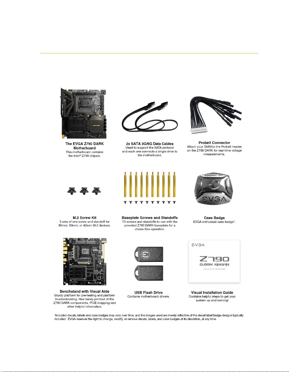
Unpacking and Parts Descriptions
The following accessories are included with the EVGA Z790 DARK
K|NGP|N Motherboard:

EVGA Z790 DARK K|NGP|N (121-RL-E799)
- 9 -
EVGA Z790 DARK K|NGP|N (121-RL-E799)
- 10 -
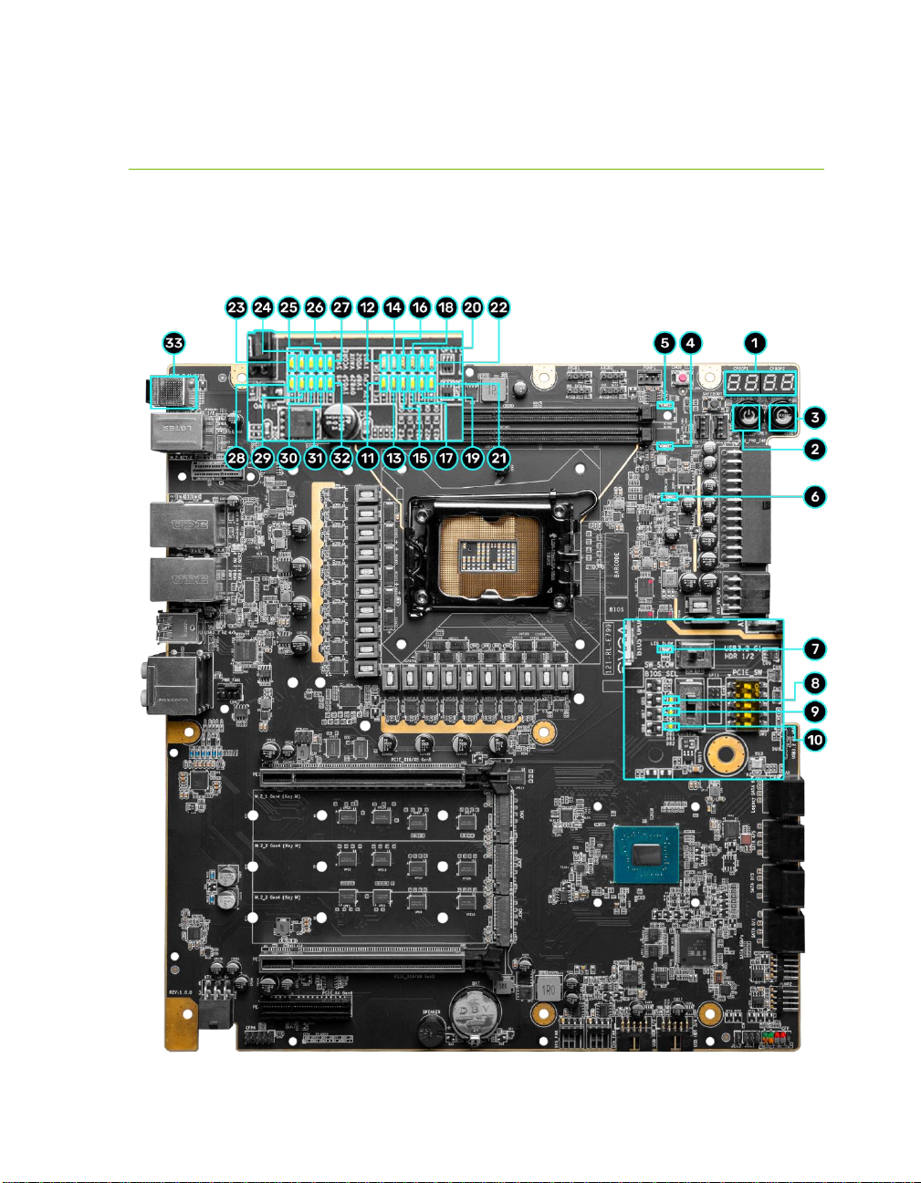
EVGA Z790 DARK K|NGP|N Motherboard LED
The EVGA Z790 DARK K|NGP|N Motherboard has several LEDs indicating power,
connectivity, and activity. Below is the location of the LEDs and their function.

EVGA Z790 DARK K|NGP|N (121-RL-E799)
- 11 -
1. Multi-function Display
a. During boot it will cycle many different hexadecimal post codes with a
range of 00-FF and this indicates what aspect of the Power On Self Test
(POST) is currently running.
i. For a list of POST Codes, please see Page 116.
b. This display can be configured in BIOS to display HW monitoring
information, such as voltage or temperature. After boot, the display will
show temperatures or voltage, depending on the BIOS configuration.
2. Power Button
a. RED: Motherboard is turned on and running.
3. Reset Button
a. WHITE: Reset button will typically flash in conjunction with HDD/SSD
LED. Depending on load, the button may flash or appear solid at times.
4. Memory DIMM 1 Status
a. OFF: DIMM detected and present
b. RED: DIMM/Memory has failed POST
5. Memory DIMM 2 Status
a. OFF: DIMM detected and present
b. RED: DIMM/Memory has failed POST
6. CATERR - Catastrophic Error on the processor
a. RED: Processor error has occurred.
b. OFF: No error state detected in the CPU.
7. SW Slow Mode ON
a. RED: Slow Mode switch has been set to enabled
1. Multi-function Display 12. PE1 Status 23. +5VSB Status
2. Power Button 13. PE2 Enabled 24. VCORE Status
3. Reset Button 14. PE2 Status 25. CPU VCCIN AUX Status
4. Memory DIMM1 Status 15. PE3 Enabled 26. CPU VDD2 Status
5. Memory DIMM2 Status 16. PE3 Status 27. CPU 1.05V Status
6. CATERR 17. M.2 Key-MM.2_1 Enabled 28. CPU 1.8V Status
7. SW Slow Mode ON 18. M.2 Key-MM.2_1 Status 29. PCH 1.05V Status
8. BIOS 1 Active 19. M.2 Key-MM.2_2 Enabled 30. PCH 0.82V Status
9. BIOS 2 Active 20. M.2 Key-MM.2_2 Status 31. PCH 1.8V Status
10. BIOS 3 Active 21. M.2 Key-MM.2_3 Enabled 32. +12V Status
11. PE1 Enabled 22. M.2 Key-MM.2_3 Status 33. CMOS CLS/BIOS Button
12. PE1 Status 24. VCORE Status
LED Legend

EVGA Z790 DARK K|NGP|N (121-RL-E799)
- 12 -
8. BIOS1 Active LED
a. WHITE: Active BIOS Chip (only 1 will be lit at a time)
9. BIOS2 Active LED
a. WHITE: Active BIOS Chip (only 1 will be lit at a time)
10. BIOS3 Active LED
a. WHITE: Active BIOS Chip (only 1 will be lit at a time)
11. PCIe Enabled for PE1. The LED stays off when PE1 is disabled or unpopulated.
a. WHITE: PE1 device present and detected.
12. PCIe Status for PE1. The LED stays off when PE1 is disabled or unpopulated.
a. WHITE: PE1 slot can be used with installed CPU.
13. PCIe Enabled for PE2. The LED stays off when PE2 is disabled or unpopulated.
a. WHITE: PE2 device present and detected.
14. PCIe Status for PE2. The LED stays off when PE2 is disabled or unpopulated.
a. WHITE: PE2 slot can be used with installed CPU.
15. PCIe Enabled for PE3. The LED stays off when PE3 is disabled or unpopulated.
a. WHITE: PE3 device present and detected.
16. PCIe Status for PE3. The LED stays off when PE3 is disabled or unpopulated.
a. WHITE: PE3 slot can be used with installed CPU.
17. M.2 Key-M Socket3 110mm (M2_1) Status LED. The LED stays off when PM1
is disabled or unpopulated.
a. WHITE: PM1 slot can be used with installed CPU.
18. M.2 Key-M Socket3 110mm (M2_1) Enabled LED. The LED stays off when
PM1 is disabled or unpopulated.
a. WHITE: PM1 device present and detected.
19. M.2 Key-M Socket3 110mm (M2_2) Status LED. The LED stays off when PM2
is disabled or unpopulated.
a. WHITE: PM2 slot can be used with installed CPU.
20. M.2 Key-M Socket3 110mm (M2_2) Enabled LED. The LED stays off when
PM2 is disabled or unpopulated.
a. WHITE: PM2 device present and detected.
21. M.2 Key-M Socket3 110mm (M2_3) Status LED. The LED stays off when PM3
is disabled or unpopulated.
a. WHITE: PM3 slot can be used with installed CPU.
22. M.2 Key-M Socket3 110mm (M2_3) Enabled LED. The LED stays off when
PM3 is disabled or unpopulated.
a. WHITE: PM3 device present and detected.
23. +5V Standby Power
a. WHITE: Voltage present (Does not mean PSU is outputting in-spec,
only that this specific voltage is detected)

EVGA Z790 DARK K|NGP|N (121-RL-E799)
- 13 -
24. VCORE Status
a. WHITE: Voltage present (Does not mean PSU is outputting in-spec,
only that this specific voltage is detected)
25. CPU VCCIN AUX Status
a. WHITE: Voltage present (Does not mean PSU is outputting in-spec,
only that this specific voltage is detected)
26. CPU VDD2 Status
a. WHITE: Voltage present (Does not mean PSU is outputting in-spec,
only that this specific voltage is detected)
27. CPU 1.05V Status
a. WHITE: Voltage present (Does not mean PSU is outputting in-spec,
only that this specific voltage is detected)
28. CPU 1.8V Status
a. WHITE: Voltage present (Does not mean PSU is outputting in-spec,
only that this specific voltage is detected)
29. PCH 1.05V Status
a. WHITE: Voltage present (Does not mean PSU is outputting in-spec,
only that this specific voltage is detected)
30. PCH 0.82V Status
a. WHITE: Voltage present (Does not mean PSU is outputting in-spec,
only that this specific voltage is detected)
31. PCH 1.8V Status
a. WHITE: Voltage present (Does not mean PSU is outputting in-spec,
only that this specific voltage is detected)
32. +12V Status
a. WHITE: Voltage present (Does not mean PSU is outputting in-spec,
only that this specific voltage is detected)
33. CMOS CLS/BIOS Buttons
RED: Always on for visibility.

EVGA Z790 DARK K|NGP|N (121-RL-E799)
- 14 -
EVGA Z790 DARK K|NGP|N Component Legend
The EVGA Z790 DARK Motherboard with the Intel®Z790 and PCH Chipset.
Figure 1 shows the motherboard and Figure 2 shows the back panel connectors
FIGURE 1. Z790 DARK K|NGP|N Motherboard Layout

EVGA Z790 DARK K|NGP|N (121-RL-E799)
- 15 -
**For a FULL description of the above legend, please see Page 17.
1. CPU Socket LGA1700 13. PCIe Slot x16/x8 25. CMOS Battery
2. Intel Z790 PCH 14. PCIe Slot x4 26. PCIe Disable Switches
3. CPU PWM Fan Headers (2 amp) 15. Power Button 27. ProbeIt Header JAT1
4. PWM/DC Fan Headers (2 amp) 16. Reset Button 28. PC Speaker
5. Pump Headers (3 amp) 17. Multi-function Display 29. BIOS Safeboot Button
6. DDR5 DIMMSlots 18. USB 3.2 Gen1 Header 30. USB to SPI for BIOS Flash
7. 24-pin ATX Power Connector 19. USB 3.2 Gen2 Type-C Header 31. SW Slow Mode Switch
8. 8-pin EPS Power Connectors 20. USB 2.0 Headers 32. Clear CMOS Button
9. Supplemental PCIe 6-pin power 21. Front Panel Audio Header 33 ARGB LED Controller Headers
10. Intel SATA6Gb/s SATAPorts 22. Front Panel Header 34. Rear Panel I/O (Figure 2)
11. ASMedia SATA6Gb/s SATAPorts 23. Temperature Sensor Header
12. 3x M.2 Socket 3 Key-M110mm 24. BIOS Selector Switch
Component Legend

EVGA Z790 DARK K|NGP|N (121-RL-E799)
- 16 -
Figure 2. Chassis Rear Panel Connectors
1. BIOS/CMOS Reset Button 5. WiFi Antenna 9. USB 3.2 Gen2x2 Type-C
2. BIOS Update Button 6. Intel i226V 2.5GbE NIC 10. Analog Audio Jacks
3. PS/2 (Keyboard+Mouse) 7. Marvell 10GbE NIC 11. Optical Out
4. USB 3.2 Gen1 Type-A 8. USB 3.2 Gen2 Type-A
I/O Hub
Intel i226V
Activity LED Status Description Speed/Link LED Status Description
Off No Data Transmission Orange 2.5Gbps data rate
Blinking (Green) Data Transmission Green 1 Gbps data rate
Off 10/100 Mbps data rate or No Link
Marvell 10GbE
Activity LED Status Description Speed/Link LED Status Description
Off No Data Transmission Orange 10Gbps data rate
Blinking Data Transmission Green 5Gbps/2.5Gbps/100Mbps/10Mbps data rate
Off No Link
Analog Audio Port
Breakdown
2/2.1 Channels
4.0/4.1 Channels 5.1 Channels 7.1 Channels
Blue Line In *Rear Speakers Out Line In
*Rear Speakers Out
Pink Mic In Mic In Mic In
Mic In
Black Side Speakers Out Side Speakers Out
Orange Center / Sub Out Center / Sub Out
3.5mm Audio Jack Legend
Front Speakers Out
Green
Front Speakers Out
Front Speakers Out /
Front Speakers + Sub
Front Speakers Out /
Front Speakers + Sub
*Only used in 7.1 and is changed via Realtek Software from within Windows.

EVGA Z790 DARK K|NGP|N (121-RL-E799)
- 17 -
Component Legend Descriptions
1. CPU Socket 1700
This is the interface for the Central Processing Unit (CPU), and supports 13th
and 12th Gen. Intel®Core i3, i5, i7 and i9 models compatible with the Intel®
LGA1700 Socket, based on Raptor Lake-S and Alder Lake-S architecture.
2. Intel®Z790 PCH
The Platform Controller Hub (PCH) works as a hub for peripherals that are less
bandwidth-intensive. The PCH has 8x DMI lanes (Gen 4), up to 20x PCIe Gen
4, and up to 8x PCIe Gen 3 lanes to allocate bandwidth to smaller PCIe slots,
M.2, USB, audio, etc.
3. PWM Fan Headers (CPU1 and CPU2)
4-pin fan headers control the fan speed via a configurable Smart curve or static
percentage. PWM control works by pulsing power to the fan at a constant rate
and sending the RPM signal to the fan’s controller. PWM control is preferred
because it eliminates voltage-based fan stall points. See Page 86 for an in-depth
breakdown of PWM controls within the BIOS.
These headers also support 12VDC fans. DC fans are controlled by decreasing
voltage to the fan, causing the fan to spin slower as less voltage is provided.
However, DC-powered fans may stall if the voltage provided is below the fan’s
minimum threshold for operation.
4. PWM/DC Fan Headers
These headers may be used with both DC and PWM fans, and may be
controlled via Smart Fan or manually within the BIOS.
5. Pump Headers (3A)
These headers are designed for use with AIO coolers and pumps designed for
PC watercooling. This header provides up to a solid 3A of power to the
connected device, helping to avoid a common issue where devices may not be
recognized due to insufficient power. These headers may be controlled via
Smart Fan or manually from within the motherboard BIOS.
6. DDR5 Memory Slots
The memory slots support up to two 288-pin DDR5 DIMMs in Dual-Channel
mode. Dual-Channel mode requires installing two sticks of supported memory.
Using only one stick of memory will lower the board to Single-Channel mode,
which may significantly lower performance. 64GB of RAM is supported in a
2x32GB configuration. At the time of this manual’s release, this motherboard

EVGA Z790 DARK K|NGP|N (121-RL-E799)
- 18 -
officially supports up to 8000MHz+ speeds. These speeds are not guaranteed,
however, because Intel®only certifies the speed of the Raptor Lake-S memory
controller up to 5600MHz, and Alder Lake-S memory controller up to
4800MHz (depending upon memory configuration).
7. 24-pin ATX power connector
The main power for the motherboard is located on the right side of the board
(See Page 40 for more information about the connector). The 24-pin connector
on the motherboard is directional and the tab on the connector must line up
with the release clip from the male 24pin connector from the power supply.
This connector provides the bulk of the power for all components.
8. 8-pin EPS Connector (Two available)
The +12V EPS provides the main power directly for the CPU (See Page 41 for
more information about the connector). Carefully choose the correct power
cable by consulting with the installation manual for your power supply.
Although PCIe and EPS cables appear similar, they are wired differently and
attaching the wrong connector may cause damage to the motherboard or
prevent the board from turning on.
Only one of the two connectors needs to be installed for basic usage (either
connector is fine). A second EPS connector should be installed for extreme
overclocking, but there is nothing wrong with installing both connectors.
Alternatively, if no power cable is connected or detected, the system will not
POST and will hang at POST code “C.”
9. Supplemental PCIe 6-pin Power Connector
The 6-pin PCIe connector at the bottom of the motherboard provides
dedicated power to the PCIe x16 slots, augmenting the +12V power provided
by the 24-pin and power directly to the GPU (See Page 40 for more information
about the connector).
This connector is optional for single VGA solutions, but is recommended for
mGPU configurations, and dual-processor video cards.
10. Intel®SATA 6Gb/s Ports
The Intel®Z790 PCH has a 6-port SATA 6Gb/s controller (See Page 50 for
more information). This controller supports SSDs, HDDs and various types of
optical devices (CDROM, DVDROM, BD-ROM, etc). The controller also
supports NCQ, TRIM, hot plug capability, and RAID levels 0/1/5/10.

EVGA Z790 DARK K|NGP|N (121-RL-E799)
- 19 -
11. ASMedia SATA 6Gb/s Ports
This ASM1061 is a secondary 2-port SATA 6GB/s controller with legacy
support for older operating systems (See Page 50 for more information about
the connectors).
12. M.2 Socket 3 Key-M 110mm (M.2_1, M.2_2, and M.2_3)
M.2 is an SSD form factor standard, which uses up to four PCIe lanes and
utilizes up to Gen4 speeds. Most popularly paired with NVMe SSDs, this
standard offers substantially faster transfer speeds and seek time than SATA
interface standards. All M.2 devices are designed to connect via a card-bus style
connector –rather than a dedicated data cable and power cable.
This slot supports device lengths of 110mm, 80mm, and 42mm.
13. PCIe Slot x16/x8*
Raptor Lake-S and Alder Lake-S processors have 20 PCIe lanes available for
routing. Unique to the Z790 DARK K|NGP|N, the PCIe Gen 5 lanes will be
automatically switched between the two x16 PE1 and PE2 slots.
When a single PCIe device is installed in either PE1 or PE2, the CPU will
allocate x16 PCIe Gen 5 lanes to the slot where the device is located. If PCIe
devices are installed in both x16 slots, both lanes will operate at x8/x8 speeds.
* Please see the description for Physical (length) vs Electrical (lanes) on Page 26.
14. PCIe Slot x4*
PCIe x4 is a smaller form-factor PCIe card slot. These can be used for low-
bandwidth products, such as a PCIe SSD card, capture card, audio card, etc.
This slot is limited to a maximum of x4 Gen4 CPU lanes.
* Please see the description for Physical (length) vs Electrical (lanes) on Page 26.
15. Power Button
This is an onboard power button, and may be used in place of, or in
conjunction with, a front panel power button wired to the board.
Open-air or test bench chassis are best served by using the onboard power
because it removes the need to wire a Power/Reset button.
16. Reset Button
This is an onboard system reset button, and may be used in place of, or in
conjunction with, a front panel system reset button wired to the board.
Open-air or test bench chassis are best served by using the onboard power
because it removes the need to wire a Power/Reset button.

EVGA Z790 DARK K|NGP|N (121-RL-E799)
- 20 -
17. Multi-function Display
This is a four-digit Power On Self-Test (“POST”) code reader, which displays in
sets of 7-segment LED. The display can show the characters 0-9, and A-F.
POST is the motherboard’s self-test to verify operational status. During POST,
the left set of LEDs will display the various codes as each motherboard segment
is analyzed, and will stop or repeatedly cycle if an error is detected. The POST
codes are listed in the troubleshooting section on Page 116.
After the system boots, these same set of LEDs can be set to display additional
temperatures or voltages. Detailed configuration instructions for the POST
Indicator are provided on Page 112.
18. USB 3.2 Gen1 Header
The USB 3.2 Gen1 header is used to connect an additional USB interface plug
to the motherboard. These will function similarly to the USB 3.2 Gen1 ports
found on the motherboard’s rear I/O hub, but can also be used for a front
panel USB device or auxiliary ports that mount in the card slots.
USB 3.2 Gen1 standard is 900ma @ 5V for unpowered devices. If your USB
device requires more power, it is recommended to attach a powered USB Hub.
Note: USB 3.2 Gen1 is more commonly referred to as USB 3.0.
19. USB 3.2 Gen2 Type-C Header
The USB 3.2 Gen2 header is used to connect an additional USB interface plug
to the motherboard. These will function similarly to the USB 3.2 Gen2 Type-C
port sometimes found on a motherboard’s rear I/O hub, but can also be used
for the chassis’ front panel USB, auxiliary ports that mount in the card slots,
and certain devices that directly connect to the header. The USB 3.2 Gen2
Header on the Z790 DARK K|NGP|N is a shielded USB 3.2 Gen2 Header
that supports up to 10Gb/s with USB 3.2 Gen2.
This USB 3.2 Gen2 Header has a power limit of 3000ma (3A) @ 5V.
20. USB 2.0 Headers
The USB 2.0 headers are used to connect additional USB interface plugs to the
motherboard. These will function similarly to the USB 2.0 ports found on the
motherboard’s hardwired I/O hub, but these can also be used for the chassis’
front panel USB, auxiliary ports that mount in the card slots, and certain devices
that directly connect to the header.
USB 2.0 standard is 500ma @ 5V per port (header total is 1000ma) for
unpowered devices. If your USB device requires more power, it is
recommended to attach a powered USB Hub.
Table of contents
Other EVGA Computer Hardware manuals

EVGA
EVGA 100-EV-EB01 User manual

EVGA
EVGA UV Plus+ 39 User manual

EVGA
EVGA GeForce RTX 2070 XC Gaming User manual

EVGA
EVGA PCoIP User manual

EVGA
EVGA Superclock User manual

EVGA
EVGA inDtube User manual

EVGA
EVGA UV Plus+ User manual

EVGA
EVGA GeForce GTX 650 Ti BOOST User manual

EVGA
EVGA CLX Series User manual

EVGA
EVGA Geforce GTX TITAN X Hybrid User manual


