SFF time N-ATX V2 User manual

SFF time N-ATX V2 manual
1
Dear customer,
Thank you for purchasing SFF time N-ATX V2 case. Please read the full compatibility list before assembling your PC. You can find the list on
our website at sfftime.com.
If you have any doubts about choosing your components, or steps in this manual, please contact us via email on [email protected], and we will
be glad to assist you.
Important notes:
- always use the correct screwdriver tip for corresponding bolts (PH1 or PH2)
- always use the correct bolt type
- do not overtight the bolts
- do not force the components in, each component should be installed without using excessive force

SFF time N-ATX V2 manual
2
SFF time N-ATX V2 specifications:
15 L volume with 405.5 x 367 x 101 mm outer dimensions
Console/"pizza box" style case with CPU and GPU fans in the same orientation
ATX power supply up to 180 mm
Vertically mounted GPU with multiple riser cable options
Support for following motherboard sizes: mini-ITX, mini-DTX, micro-ATX, ATX
Support for 380mm long triple slot graphic card, or 4 slot if using ITX sized motherboard
Support for 360mm radiators
CPU coolers up to 79 mm in height
Support for a 3.5" drive and up to eleven 2.5" drives
Back of motherboard accessible for cooler installation
Front USB-C gen3.2 port
Sturdy powder-coated aluminum construction
Narrow footprint - 120 mm wide with included stand
Inverted layout option
1.95 kg weight

SFF time N-ATX V2 manual
3
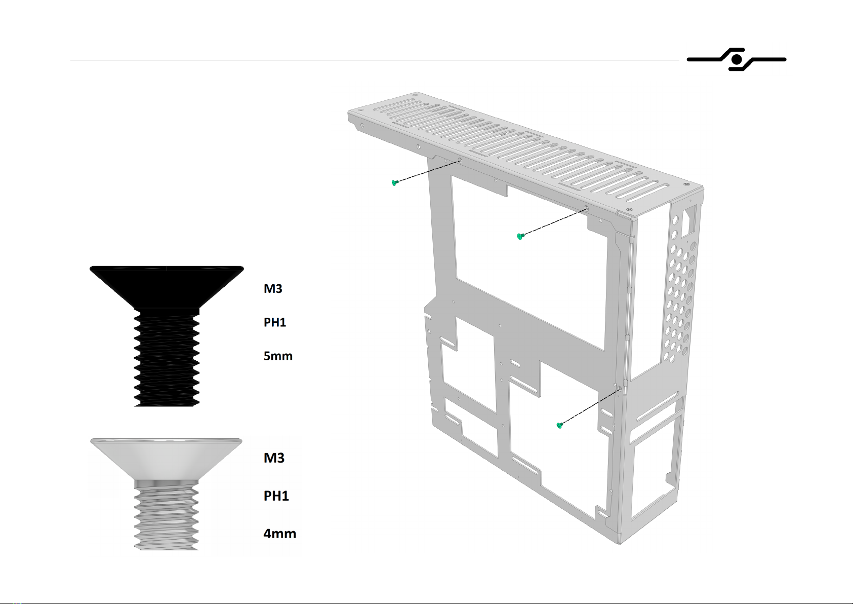
1. Case assembly (part 1)
- your case will come with
separated chassis panels and
you will need to assemble them
before installing your parts in it
- start by attaching the rear
panel to the top panel with two
5mm countersunk bolts
- beware of parts orientation
- be careful not to over torque
the bolts as you are screwing
into aluminum
SFF time N-ATX V2 manual
4
2. Case assembly (part 2)
- continue by attaching the MBO tray
to the rear and top panel
- use two 5mm countersunk bolts for
top panel, and 4mm countersunk
bolt for the rear panel (silver finish)

SFF time N-ATX V2 manual
5
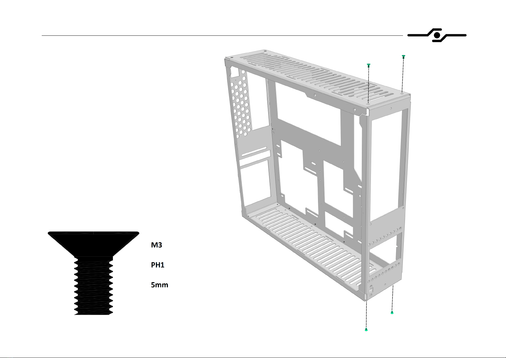
3. Case assembly (part 3)
- now attach the bottom panel to the
MBO tray and to the rear panel with
five 5mm countersunk bolts
SFF time N-ATX V2 manual
6
4. Case assembly (part 4)
- next step is to attach the front
panel to top and bottom panels
with four 5mm countersunk bolts
SFF time N-ATX V2 manual
7
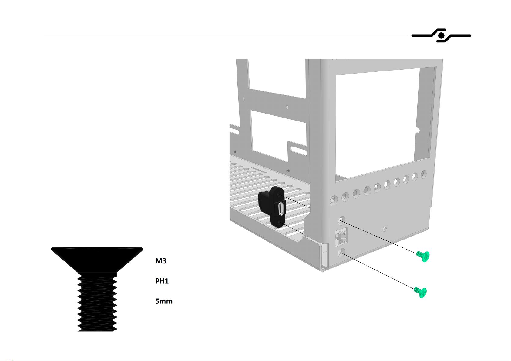
5. Case assembly (part 5)
- before attaching the mask, you first need
to install the USB-C cable
- use two 5mm countersunk bolts to secure
it to the front panel
-if you want to install more than two
2.5” drives you need to do it now,
before attaching the mask. Please see
step 26 for further instructions
SFF time N-ATX V2 manual
8
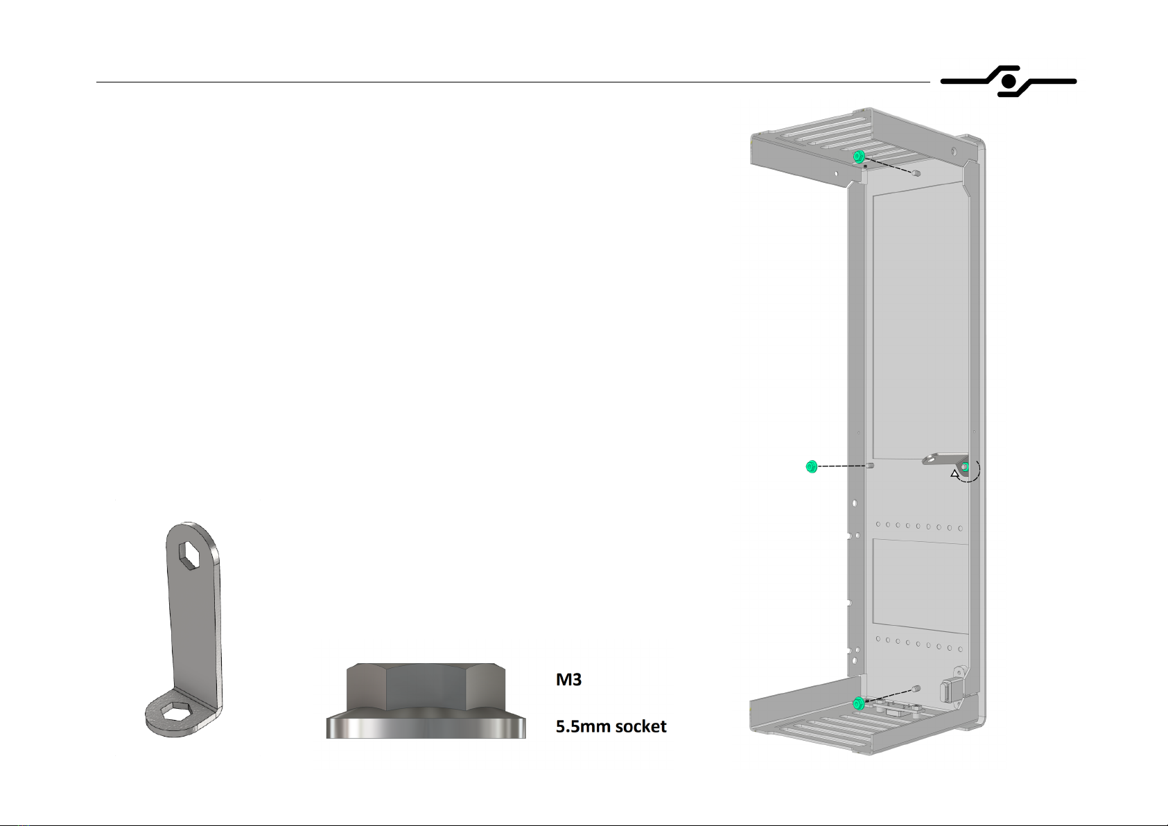
6. Case assembly (part 6)
- now you can attach the mask to the front panel
using four M3 flanged nuts with provided hex tool
SFF time N-ATX V2 manual
9
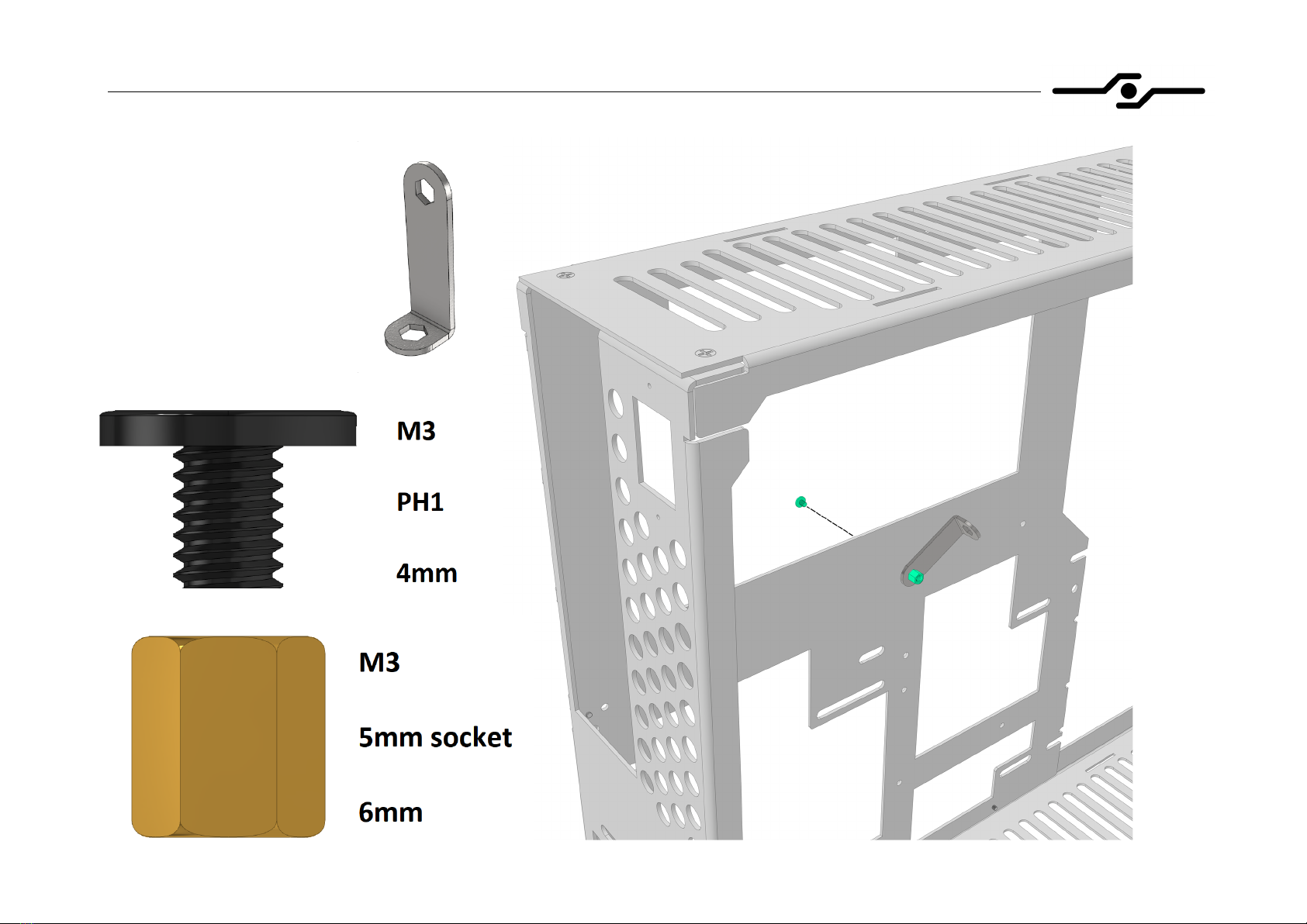
7. Installing the motherboard – preparing standoffs (part 1)
- to install standoffs, you
need a standoff and a
bolt that holds it
- screw the standoff to
the bolt with your hands
- to tighten the standoff,
use screwdriver and
provided hex tool, as
shown in the picture

SFF time N-ATX V2 manual
10
8. Installing the motherboard – preparing standoffs (part 2)
- following pictures show standoff
configurations for different motherboard sizes
- always install correct standoffs, otherwise you
could damage the motherboard

SFF time N-ATX V2 manual
11
9. Installing the motherboard – bolts and cables
- prepare the motherboard by installing CPU, RAM,
M.2 drives, and CPU air cooler if using one
-install the IO shield
- align the motherboard on the standoffs
- screw the motherboard down using provided bolts
- after installing the motherboard, connect internal
USB-C cable and power switch connector
- if you are not sure about motherboard connector
positions, please consult its manual
SFF time N-ATX V2 manual
12
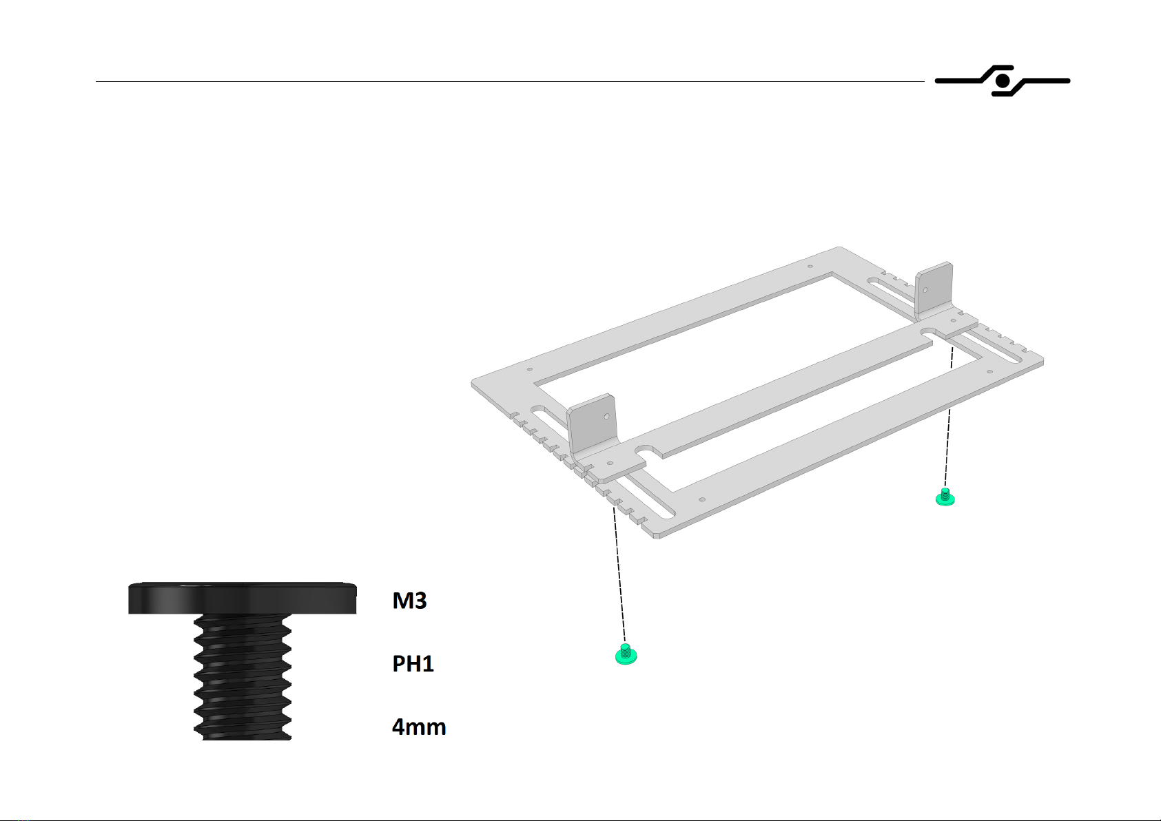
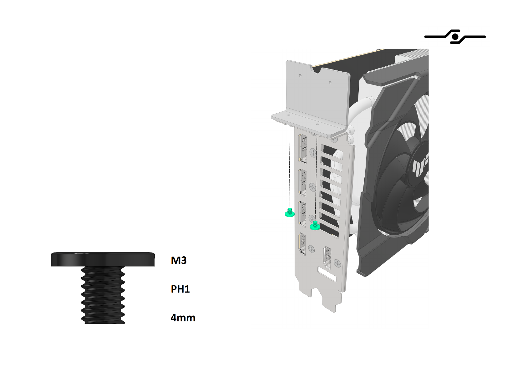
10. Installing GPU riser cable – preparing the riser bracket (part 1)
- attach two parts of the riser bracket using two
pan head 4mm bolts like shown in the picture
- the bottom part should be oriented in a way
that its M3 extrusions face towards the top
part
- before tightening the bolts down fully, select
the position of the top part corresponding to
your GPU thickness (1-4 slot options)
-you can review all the possible options on
the next page

SFF time N-ATX V2 manual
13
11. Installing GPU riser cable – preparing the riser bracket (part 2)
- this picture shows all the positions in which
you can mount the top part of the bracket,
depending on your GPU thickness
- you can also position it in between two
steps if you want to fine tune the distance
from the GPU to the side panel
SFF time N-ATX V2 manual
14
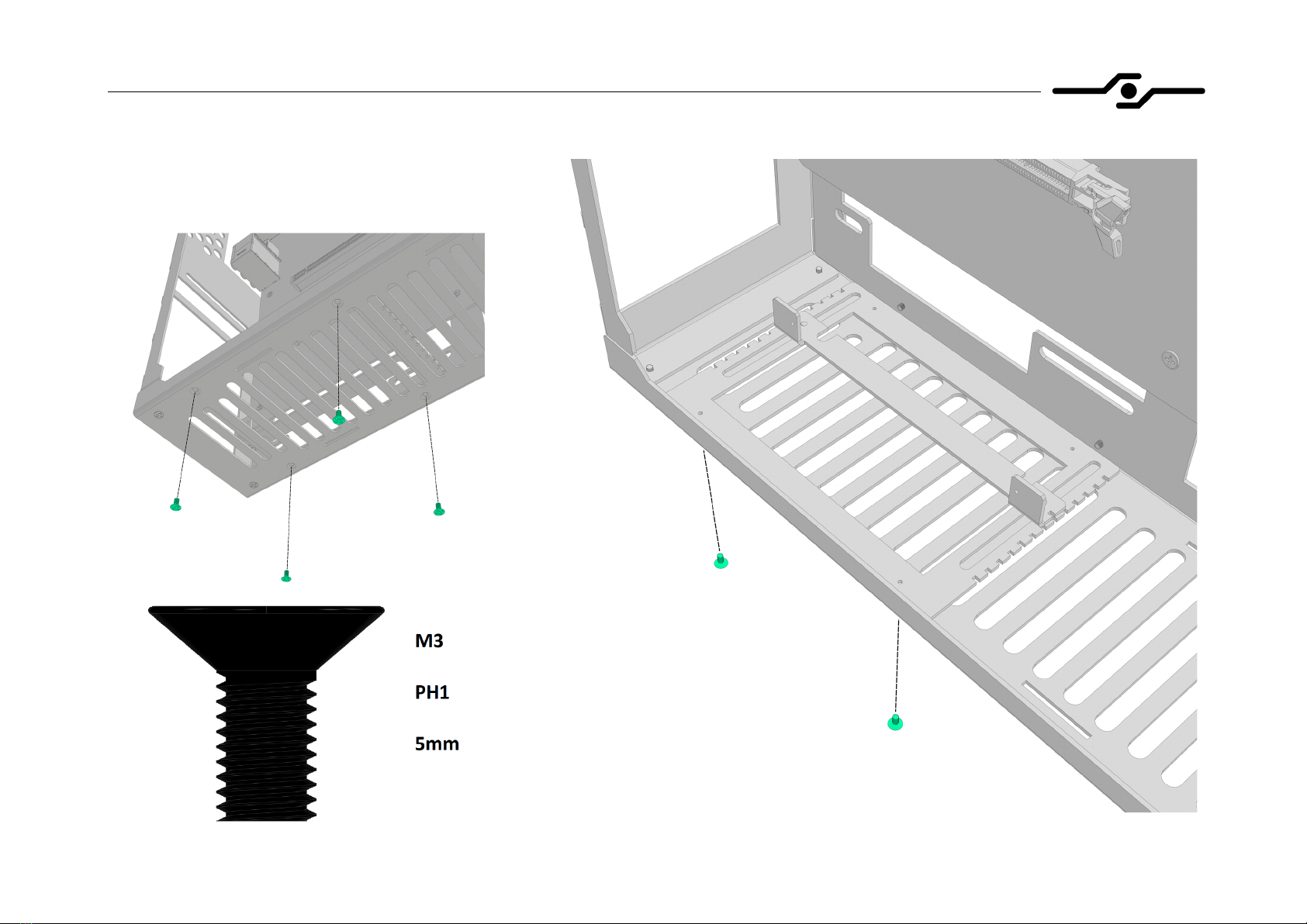
12. Installing GPU riser cable – preparing the riser bracket (part 3)
- attach the assembled riser bracket to
the bottom of the chassis with four
5mm countersunk bolts
SFF time N-ATX V2 manual
15
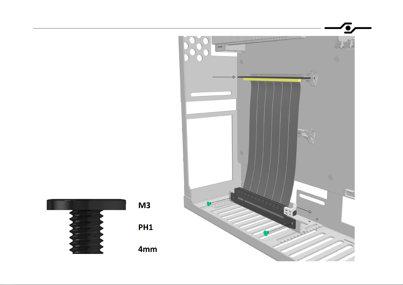
13. Installing GPU riser cable – riser and bolts
- install the male end of the riser into the motherboard
- screw down the female end of the riser onto
previously installed riser bracket
- unlatch the clip on the female end
- depending on your configuration, you may need to
bend the riser a bit
SFF time N-ATX V2 manual
16
14. Installing the GPU – GPU bracket
- before installing the GPU, you need to attach the
GPU bracket to it, as shown in the picture
- put washers under the bolt heads in necessary
- screw down the GPU bracket to the GPU
SFF time N-ATX V2 manual
17
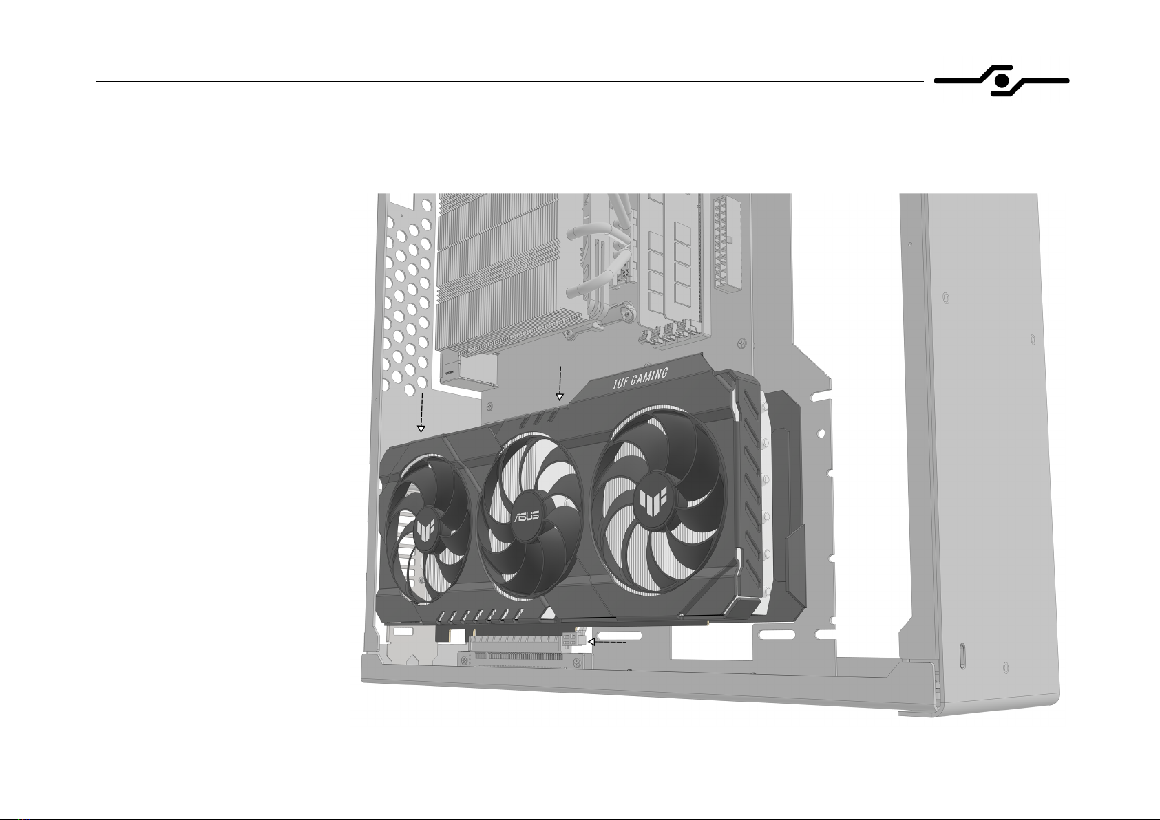
15. Installing the GPU – GPU
- install the GPU into the riser
- be sure that it is fully seated
- latch the riser clip to its
locked position
- if your GPU is very tall, you
might want to install it along
with the riser
SFF time N-ATX V2 manual
18
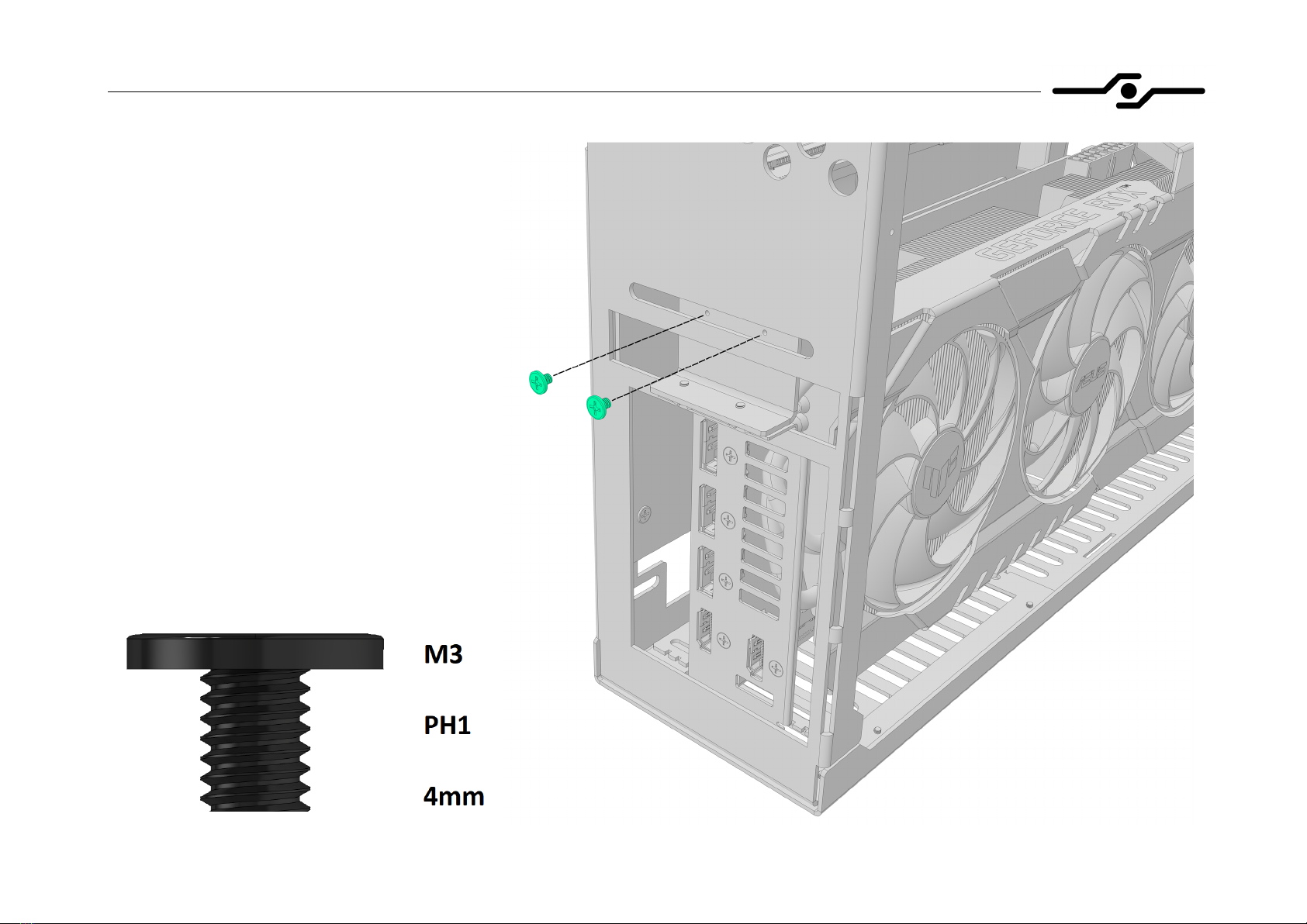
16. Installing the GPU – bolts
- screw down the GPU bracket to the
case with two screws
- put washers under the bolt heads if
necessary
SFF time N-ATX V2 manual
19
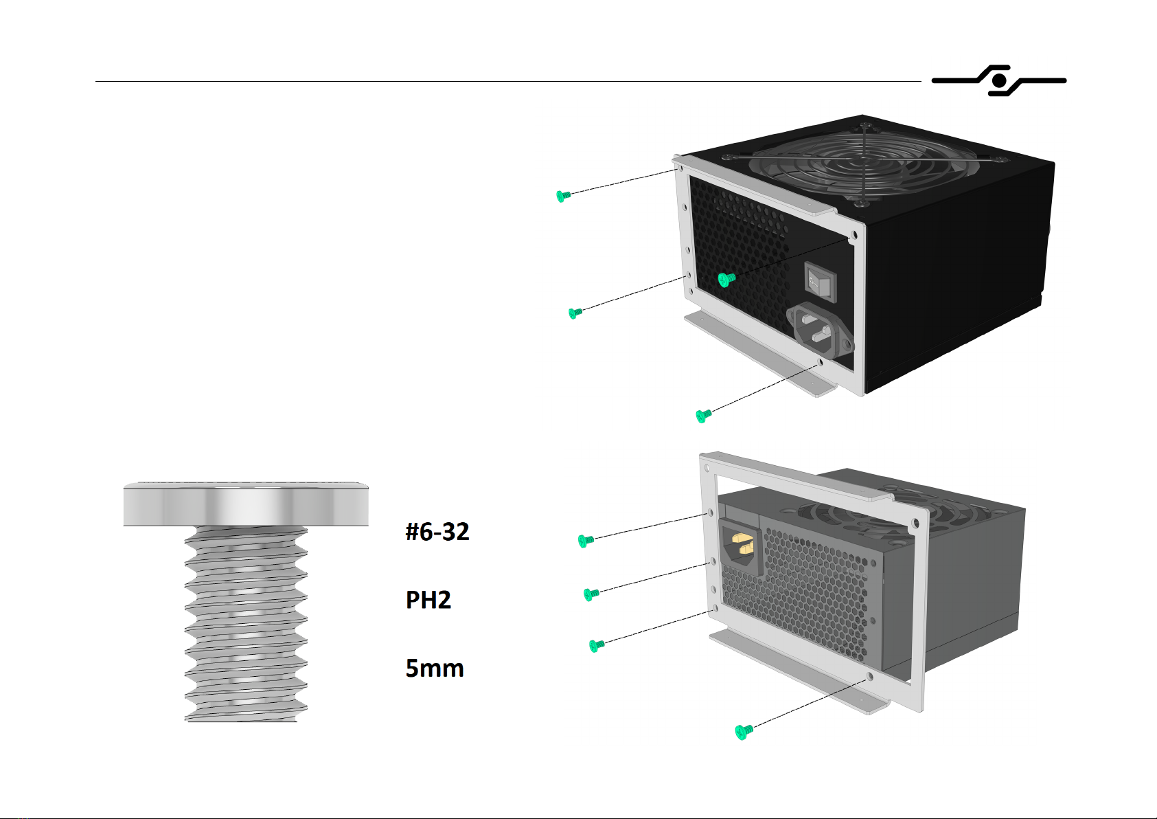
17. Installing the power supply – PSU bracket
- screw down the power supply to the
bracket using four silver #6-32 bolts
- we recommend using bolts supplied with
your PSU, as they vary in length
SFF time N-ATX V2 manual
20
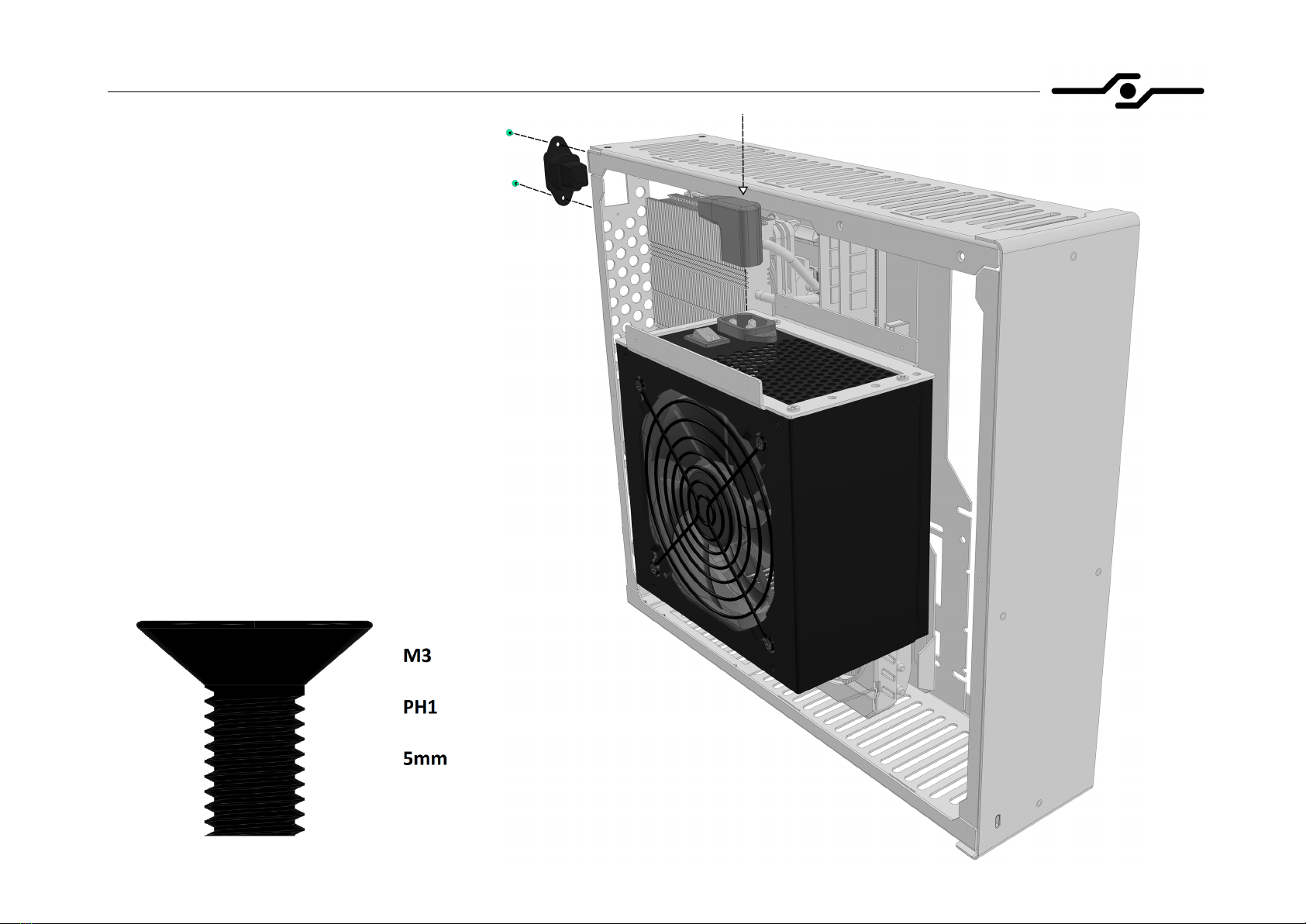
18. Installing the power supply – cable
- before installing the power supply into
the case, screw down the internal AC
cable to the rear side of the case using
two 5mm countersunk bolts
- insert the AC plug into the connector on
the power supply like shown in the
picture


