Kontron VRack 4U Series User manual

VRack 4U Systems
User's Guide (prelim. version V0.99 prelim)
www.kontron.com
www.kontron.com

This page is intentionally left blank.

1. Table of Contents VRack 4U – User's Guide (prelim. version V0.99)
1. Table of Contents
1. Table of Contents ..................................................................................................................................... 1
1.1. Table of Figures...................................................................................................................................... 3
2. Introduction ........................................................................................................................................... 4
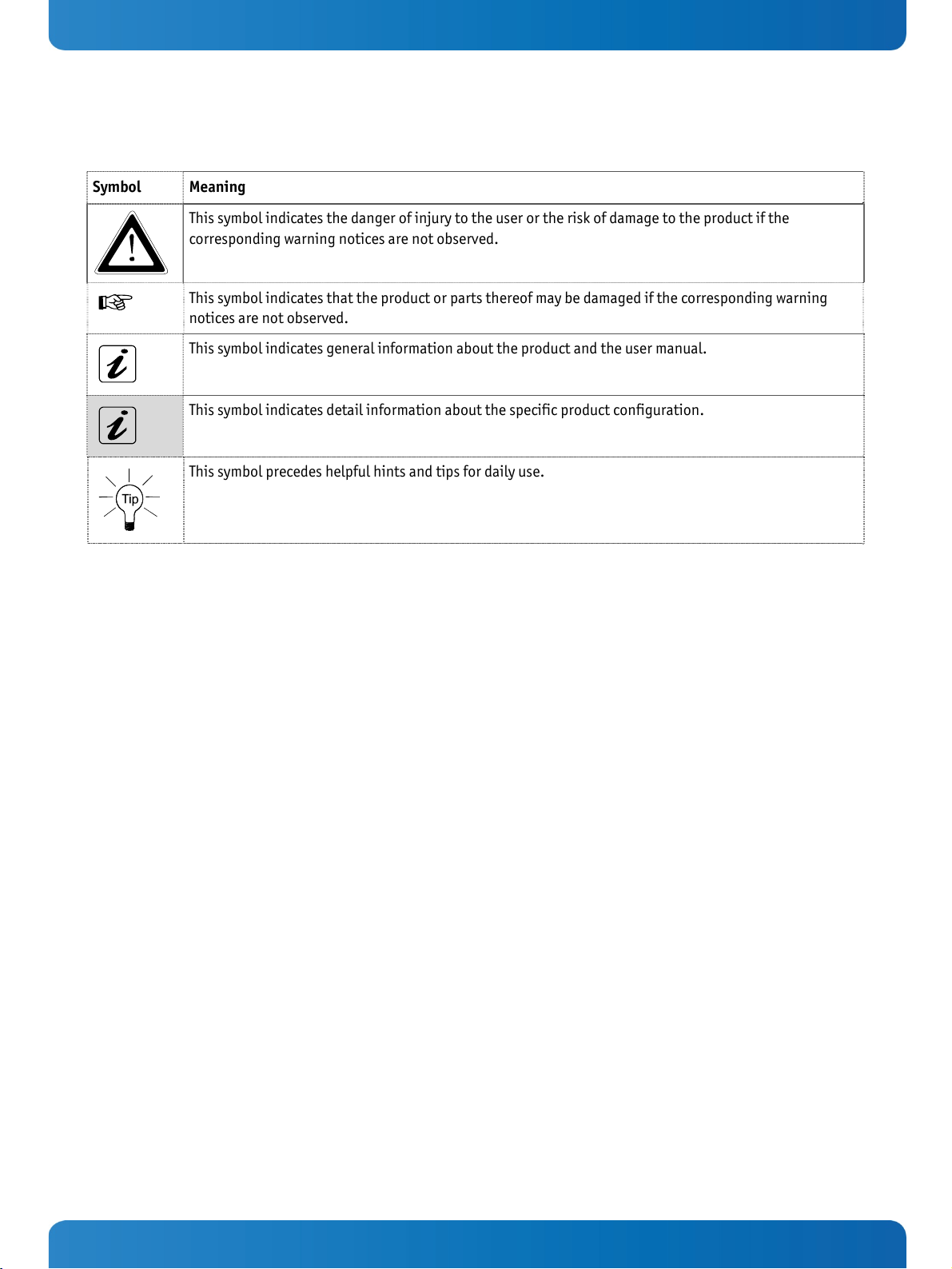
2.1. Symbols used in this Manual..................................................................................................................... 5
3. Important Instructions............................................................................................................................. 6
3.1. Warranty Note ....................................................................................................................................... 6
3.2. Exclusion of Accident Liability Obligation.................................................................................................... 6
3.3. Liability Limitation / Exemption from the Warranty Obligation ........................................................................ 6
4. General Safety Instructions for IT Equipment............................................................................................... 7
4.1. Operation of Laser Source Devices ............................................................................................................. 8
4.2. Electrostatic Discharge (ESD) ................................................................................................................... 9
4.2.1. Grounding Methods.......................................................................................................................... 9
4.3. Instructions for the Lithium Battery........................................................................................................... 9
5. Electromagnetic Compatibility (Class A Device) ..........................................................................................10
5.1. Electromagnetic Compatibility (EU) ..........................................................................................................10
5.2. FCC Statement (USA)..............................................................................................................................10
5.3. EMC Compliance (Canada) .......................................................................................................................10
6. Scope of Delivery ....................................................................................................................................11
6.1. Type Label and Product Identification .......................................................................................................11
7. Product Description ................................................................................................................................12
7.1. Front Side ............................................................................................................................................15
7.1.1. Interfaces and Controls on the Front Side ............................................................................................17
7.1.2. Controls and Indicators....................................................................................................................17
7.1.3. Front Access Panel ..........................................................................................................................18
7.1.4. Cover Fastening Screw on the Front Side .............................................................................................18
7.1.5. Filter Mat and Filter Mat Holder .........................................................................................................19
7.1.6. Drive Bays .....................................................................................................................................19
7.2. Rear Side .............................................................................................................................................20
7.2.1. Power Supply .................................................................................................................................20
7.2.2. External Interfaces of the DZ77-SL-50K Motherboard.............................................................................21
7.2.3. External Interfaces of the KTQ45/ATXE Motherboard..............................................................................21
7.3. Side View .............................................................................................................................................22
7.4. Fans....................................................................................................................................................22
8. Assembly, Disassembly............................................................................................................................23
8.1. Attaching the Rubber Feet ......................................................................................................................23
8.2. Cover ..................................................................................................................................................23
8.3. Accessing Internal Components ...............................................................................................................24
8.3.1. Installing/Removing the Expansion Cards ...........................................................................................24
8.4. Installation in a 19" Industrial Cabinet .....................................................................................................26
9. Starting Up ............................................................................................................................................27
9.1. AC Power Connection .............................................................................................................................27
9.2. Operating System and Hardware Component Drivers ....................................................................................28
www.kontron.com 1

1. Table of Contents VRack 4U – User's Guide (prelim. version V0.99)
10. Maintenance and Prevention.................................................................................................................. 29
10.1. Cleaning the Filter Mat ......................................................................................................................... 29
10.2. Replacing the Lithium Battery ............................................................................................................... 31
11. Slide Rails (Option) .............................................................................................................................. 32
12. Technical Data...................................................................................................................................... 33
12.1. Electrical Specifications ....................................................................................................................... 33
12.2. Mechanical Specifications..................................................................................................................... 34
12.3. Environmental Specifications ................................................................................................................ 34
12.4. CE Directives and Standards .................................................................................................................. 35
13. Standard Interfaces – Pin Assignments ................................................................................................... 36
13.1.1. Serial Interface (RS232) ................................................................................................................ 36
13.1.2. VGA Port ..................................................................................................................................... 36
13.1.3. Combined PS/2 Keyboard and Mouse Connector ................................................................................. 37
13.1.4. PS/2 Keyboard Connector .............................................................................................................. 37
13.1.5. PS/2 Mouse Connector................................................................................................................... 37
13.1.6. Parallel Port (LPT)......................................................................................................................... 38
13.1.7. USB Port ..................................................................................................................................... 38
14. Technical Support................................................................................................................................. 39
14.1. Returning Defective Merchandise ........................................................................................................... 39
2www.kontron.com

1. Table of Contents VRack 4U – User's Guide (prelim. version V0.99)
1.1. Table of Figures
Fig. 1: Laser radiation warning label ................................................................................................................8
Fig. 2: VRack 4U - configuration with DVD drive and internal HDD ........................................................................ 11
Fig. 3: VRack 4U - cofiguration with DVD and DA435 drives ................................................................................. 11
Fig. 4: VRack 4U - side view with opened access panel........................................................................................ 12
Fig. 5: VRack 4U, opened (shown as VRack DZ77-A with external accessible drives only ............................................13
Fig. 6: VRack 4U opened (shown as VRack 4U DZ77-A with internal HDD and external accessible drive)........................ 14
Fig. 7: Front side with closed front access panel ............................................................................................... 15
Fig. 8: Front side with opened access panel ..................................................................................................... 16
Fig. 9: Controls, indicators and USB ports at the front side ................................................................................. 17
Fig. 10: LED indicators on the front side.......................................................................................................... 18
Fig. 11: Front accessibile drive bays (e.g. D1 equipped with a DVD drive)............................................................... 19
Fig. 12: Rear side of a VRack 4U platform (shown as VRack DZ77-A; the expansion cards are as example only) .............. 20
Fig. 13: External ports of the Intel® DZ77 motherboard ..................................................................................... 21
Fig. 14: External ports of the KTQ45/ATXE motherboard ..................................................................................... 21
Fig. 15: VRack 4U platform – side view ............................................................................................................ 22
Fig. 16: Inside of the cover with fixing brackets................................................................................................ 23
Fig. 17: Loosening the knurled cover fastening screw on the front side ................................................................. 25
Fig. 18: Pull out the cover with the fixing bolts on the rear ................................................................................. 25
Fig. 19: VRack with removed cover ................................................................................................................. 25
Fig. 20: VRack 4U, rear side (shown as VRack 4U DZ77-A) ................................................................................... 27
Fig. 21: Detail: Filter mat holder on the front side of the VRack 4U platform ........................................................... 29
Fig. 22: Detail: without filter mat at the front side ............................................................................................ 30
Fig. 23: Filter mat holder without filter mat ..................................................................................................... 30
Fig. 24: Filter mat holder with filter mat.......................................................................................................... 30
Fig. 25: Filter mat ....................................................................................................................................... 30
Fig. 26: Lithium Battery location ................................................................................................................... 31
www.kontron.com 3

2. Introduction VRack 4U – User's Guide (prelim. version V0.99)
2. Introduction
Kontron Technology India would like to point out that the information contained in this manual may be subject to
technical alteration, particularly as a result of the constant upgrading of Kontron Technology India products. The
attached documentation does not entail any guarantee on the part of Kontron Technology India with respect to technical
processes described in the manual or any product characteristics set out in the manual. Kontron Technology India does
not accept any liability for any printing errors or other inaccuracies in the manual unless it can be proven that Kontron
Technology India is aware of such errors or inaccuracies or that Kontron Technology India is unaware of these as a result
of gross negligence and Kontron Technology India has failed to eliminate these errors or inaccuracies for this reason.
Kontron Technology India expressly informs the user that this manual only contains a general description of technical
processes and instructions which may not be applicable in every individual case. In cases of doubt, please contact
Kontron Technology India.
This manual is protected by copyright. All rights are reserved by Kontron Technology India. Copies of all or part of this
manual or translations into a different language may only be made with the prior written consent of Kontron Technology
India. Kontron Technology India points out that the information contained in this manual is constantly being updated in
line with the technical alterations and improvements made by Kontron Technology India to the products and thus this
manual only reflects the technical status of the products by Kontron Technology India at the time of printing.
© 2013 by Kontron Technology India
Printing and duplication, even of sections, is only permissible with the express approval of
Kontron Technology India Pvt Ltd
#425 , 2nd Main Road,
Kasturinagar,
East of N.G.E.F.,
Bangalore - 560 043
INDIA
4www.kontron.com

2. Introduction VRack 4U – User's Guide (prelim. version V0.99)
2.1. Symbols used in this Manual
Symbol Meaning
This symbol indicates the danger of injury to the user or the risk of damage to the product if the
corresponding warning notices are not observed.
This symbol indicates that the product or parts thereof may be damaged if the corresponding warning
notices are not observed.
This symbol indicates general information about the product and the user manual.
This symbol indicates detail information about the specific product configuration.
This symbol precedes helpful hints and tips for daily use.
www.kontron.com 5

3. Important Instructions VRack 4U – User's Guide (prelim. version V0.99)
3. Important Instructions
This manual provides important information required for the proper operation of the VRack 4U platform!
This chapter contains instructions which must be observed when working with the VRack 4U platform.
3.1. Warranty Note
Due to their limited service life, parts which by their nature are subject to a particularly high degree of wear (wearing
parts) are excluded from the warranty beyond that provided by law. This applies to batteries, for example.
3.2. Exclusion of Accident Liability Obligation
Kontron Technology India shall be exempted from the statutory accident liability obligation if the user fails to observe the
“General Safety Instructions for IT Equipment” chapter, the hints in this manual or eventually the warning signs label on
the device.
3.3. Liability Limitation / Exemption from the Warranty Obligation
In the event of damage to the device caused by failure to observe the “General Safety Instructions for IT Equipment”
chapter, the hints in this manual or eventually the warning signs label on the device, Kontron Technology India shall not
be required to honor the warranty even during the warranty period and shall be exempted from the statutory accident
liability obligation.
6www.kontron.com

4. General Safety Instructions for IT Equipment VRack 4U – User's Guide (prelim. version V0.99)
4. General Safety Instructions for IT Equipment
Caution:
Energy hazards >240 VA are present inside the chassis!
Activities such as system expansion with expansion cards, or maintanance have to be carried-out by
qualified personnel familiar with the associated dangers!
The installation instructions for the VRack 4U platform is the responsibility of the distributor.
When used as intended the VRack 4U platform is to operate only closed and locked.
Only when the cover is properly installed, secured with the knurled screws on the rear and the cover
fastening screw on the front, and the access panel is locked with the key, it is ensured that the user
doesn’t have access to the internal parts of the VRack 4U platform, loaded with hazardous energy.
Please read this passage carefully and take careful note of the instructions, which have been compiled for your safety and
to ensure to apply in accordance with intended regulations. If the following general safety instructions are not observed,
it could lead to injuries to the operator and/or damage of the VRack 4U; in cases of non-observance of the instructions
Kontron is exempt from accident liability, this also applies during the warranty period.
The VRack 4U has been built and tested according to the basic safety requirements for low voltage (LVD) applications and
has left the manufacturer in safety-related, flawless condition. To maintain this condition and to also ensure safe
operation, the operator must not only observe the correct operating conditions for the VRack 4U but also the following
general safety instructions:
The VRack 4U must be used as specified in the documentation, in which the instructions for safety for the product and
for the service person/operator are described. These contain guidelines for setting up, installation and assembly,
maintenance, transport or storage.
The on-site electrical installation must meet the requirements of the country's specific local regulations.
If a power cable comes with the VRack 4U, only this cable should be used. Do not use an extension cable to connect
the VRack 4U.
To guarantee that sufficient air circulation is available to cool the VRack 4U, please ensure that the ventilation
openings are not covered or blocked. If a filter mat is provided, this should be cleaned regularly. Do not place the
system close to heat sources or damp places. Make sure the system is well ventilated.
Only devices or parts which fulfill the requirements of SELV circuits (Safety Extra Low Voltage) as stipulated by IEC
60950-1 may be connected to the available interfaces.
Before opening the device, make sure that the device is disconnected from the mains.
Switching off the device by its power button does not disconnect it from the mains. Complete disconnection is only
possible if the power cable is removed from the wall plug or from the device. Ensure that there is free and easy access
to enable disconnection.
The device may only be opened for the insertion or removal of add-on cards (depending on the configuration of the
system). This may only be carried out by qualified service persons for this area.
If extensions are being carried out, the following must be observed:
all effective legal regulations and all technical data are adhered to
the power consumption of any add-on card does not exceed the specified limitations
the current consumption of the system does not exceed the value stated on the type label of VRack 4U.
Only original accessories that have been approved by Kontron can be used.
Please note: safe operation is no longer possible when any of the following applies:
the device has visible damages or
the device is no longer functioning
In this case the device must be switched off and it must be ensured that the device can no longer be operated.
www.kontron.com 7

4. General Safety Instructions for IT Equipment VRack 4U – User's Guide (prelim. version V0.99)
Additional safety instructions for DC power supply circuits
To guarantee safe operation of devices with DC power supply voltages larger than 60 volts DC or a power consumption
larger than 240 VA, please observe that:
the device is set up, installed and operated in a room or enclosure marked with “RESTRICTED ACCESS”, if there are
no safety messages on VRack 4U system as safety signs and labels on the device itself.
no cables or parts without insulation in electrical circuits with dangerous voltage or power should be touched
directly or indirectly
a reliable protective earthing connection is provided
a suitable, easily accessible disconnecting device is used in the application (e.g. overcurrent protective device), if
the device itself is not disconnect able
a disconnect device, if provided in or as part of the equipment, shall disconnect both poles simultaneously
interconnecting power circuits of different devices causes no electrical hazards
A sufficient dimensioning of the power cable wires must be selected – according to the maximum electrical
specifications on the type label as stipulated by EN60950-1 or VDE0100 or EN60204 or UL508 regulations.
The devices do not generally fulfill the requirements for "centralized DC power systems“ (UL 60950-1, Annex NAB; D2)
and therefore may not be connected to such devices!
4.1. Operation of Laser Source Devices
Fig. 1: Laser radiation warning label
The optional DVD drives contain light-emitting diodes (classified in accordance with IEC 825-1:1993, EN 60825:1997:
LASER CLASS 1 and therefore must not be opened.
If the enclosure of such a drive is opened, invisible laser radiation is emitted. Do not allow yourself to be exposed to this
radiation.
The laser system meets the code of Federal Regulations 21 CFR, 1040 for the USA and the Canadian Radiation Emitting
Devices Act, REDR C 1370.
8www.kontron.com

4. General Safety Instructions for IT Equipment VRack 4U – User's Guide (prelim. version V0.99)
4.2. Electrostatic Discharge (ESD)
A sudden discharge of electrostatic electricity can destroy static-sensitive devices or micro-circuitry. Proper packaging
and grounding techniques are necessary precautions to prevent damage. Always take the following precautions:
1. Transport boards in static-safe containers such as boxes or bags.
2. Keep electrostatic sensitive parts in their containers until they arrive at the ESD-safe workplace.
3. Always be properly grounded when touching a sensitive board, component, or assembly.
4. Store electrostatic-sensitive boards in protective packaging or on antistatic mats.
4.2.1. Grounding Methods
The following measures help to avoid electrostatic damages to the device:
1. Cover workstations with approved antistatic material. Always wear a wrist strap connected to workplace as well as
properly grounded tools and equipment.
2. Use anti-static mats, heel straps, or air ionizes to give added protection.
3. Always handle electrostatic sensitive components by their edge or by their casing.
4. Avoid contact with pins, leads, or circuitry.
5. Turn off power and input signals before inserting and removing connectors or connecting test equipment.
6. Keep work area free of non-conductive materials such as ordinary plastic assembly aids and styrofoam.
7. Use field service tools such as cutters, screwdrivers, and vacuum cleaners which are conductive.
8. Always place drives and boards PCB-assembly-side down on the foam.
4.3. Instructions for the Lithium Battery
The installed motherboard or SBC (Single Board Computer) is equipped with a Lithium battery. When replacing the
lithium battery, please follow the corresponding instructions in the chapter 10.2 “Replacing the Lithium Battery”.
Caution
Danger of explosion when replacing with wrong type of battery. Replace only with the same or equivalent
type recommended by the manufacturer. The lithium battery type must be UL recognized.
Do not dispose of lithium batteries in general trash collection. Dispose of the battery according to the
local regulations dealing with the disposal of these special materials, (e.g. to the collecting points for
dispose of batteries).
www.kontron.com 9

5. Electromagnetic Compatibility (Class A Device) VRack 4U – User's Guide (prelim. version V0.99)
5. Electromagnetic Compatibility (Class A Device)
5.1. Electromagnetic Compatibility (EU)
This product is intended only for use in industrial areas. The most recent version of the EMC guidelines (EMC Directive
2004/108/EC) and/or the German EMC laws apply. If the user modifies and/or adds to the equipment (e.g. installation of
add-on cards) the prerequisites for the CE conformity declaration (safety requirements) may no longer apply.
Warning!
This is a class A product. In domestic environment this product may cause radio interference in which case the user may
be required to take adequate measures.
5.2. FCC Statement (USA)
This equipment has been tested and found to comply with the limits for a Class A digital device, pursuant to Part 15 of the
FCC Rules. These limits are designed to provide reasonable protection against harmful interference when the equipment is
operated in commercial environment. This equipment generates, uses, and can radiate radio frequency energy and, if not
installed and used in accordance with the instruction manual, may cause harmful interference to radio communications.
Operation of this equipment in residential area is likely to cause harmful interference in which case the user will be
required to correct the interference at his own expense.
5.3. EMC Compliance (Canada)
The method of compliance is self-declaration to Canadian standard ICES-003:
(English): This Class A digital apparatus complies with the Canadian ICES-003.
(French): Cet appareil numérique de la class A est conforme à la norme NMB-003 du Canada.
10 www.kontron.com

6. Scope of Delivery VRack 4U – User's Guide (prelim. version V0.99)
6. Scope of Delivery
VRack 4U platform (system configuration ordered)
Two keys for the access panel lock
Rubber feet (self-adhesive)
AC power cord
Optional Parts:
Slide rails
6.1. Type Label and Product Identification
The type label (product designation, serial number) and the inspection status label of your VRack 4U platform are located
on the right side of the device.
System Type Product Designation Product Identifikation
VRack 4U VRack 4U xxxxxxxx-y VRack 4U = System type
The “xxxxxxxxx” group is replaced by up to a max. 8-digit combination of
numbers, letter or space, and represents the installed CPU board
The “y” is replaced by a single letter (A through Z) representing the
power supply installed into the system.
Note for power supplies (PSU):
A: corresponds to the systems with a 400W wide range AC power supply
Fig. 2: VRack 4U - configuration with DVD drive and internal HDD Fig. 3: VRack 4U - cofiguration with DVD and DA435 drives
www.kontron.com 11

7. Product Description VRack 4U – User's Guide (prelim. version V0.99)
7. Product Description
The VRack 4U platform expands the Kontron 4U platform line line. VRack 4U is a scalable 4U (19") platform, that can be
equipped with different motherboards, supporting various system configurations (refer to “VRack 4U Systems -
Configuration Guides” on our website). The flexible customer-specific hardware system configuration and the robust
construction with excellent mechanical stability of the VRack 4U platform offer the superior qualities of a computer
designed for operation in harsh industrial environment.
The VRack 4U platform is designed to be installed in 19" racks. It may be used as desktop version.
Fig. 4: VRack 4U - side view with opened access panel
The system can be equipped with up to five drive bays (depending on the system configuration ordered):
D1, D2 and D3: three 5.25" front accessible drive bays
D4 and D5: two internal 3.5" drive bay
D6: 3.5" front accessible drive bay
The power button of the VRack 4U platform is located on the front side behind the front access panel. The LED indicators
are located on the front side and consist of a “power LED” and a “hard disk activity LED”.
Two of the system fans are installed at the front side of the unit.
The washable filter mat which protects your system against dust and dirt is located on the front side of the system. This
filter mat can be replaced during operation.
The type label is attached to the right side of the device.
The VRack 4U platform may be operated in horizontal position.
When powering on the VRack 4U system, make sure that the air intake and exhaust openings are not
obstructed by objects.
For using as desktop unit, four rubber feet are included in the accessory. To attach the rubber feet,
please follow the instructions in chapter 8.1 “Attaching the Rubber Feet”.
12 www.kontron.com

7. Product Description VRack 4U – User's Guide (prelim. version V0.99)
13
9
7
14
3 4
1
2
1
5
811
16
15
12
6
10
Fig. 5: VRack 4U, opened (shown as VRack DZ77-A with external accessible drives only
119" rack bracket with handle
2Front access panel
3Access panel lock
4Cover retaining plate on the front side
5D1, D2, D3, D6: front accessible drives (mounted
on top of each other in a drive cage)
6Card hold down bracket (for short expansion
cards)
7Fastening screw for the card hold down bracket
(internal accessible)
8AC power supply unit
9External interfaces of the motherboard
10 Exhaust openings on the rear side
11 Slots for expansion cards
12 Lithium Battery (CMOS)
13 Motherboard
14 Card guides (for full-length cards)
15 Drive bracket for two internal 3.5" drive bay (D4, D5)
(shown without installed internal HDDs)
16 System fans
Note: for drive location, refer also Fig. 11.
www.kontron.com 13

7. Product Description VRack 4U – User's Guide (prelim. version V0.99)
13
9
7
14
3 4
1
2
1
5
811
15
12
16
6
10
Fig. 6: VRack 4U opened (shown as VRack 4U DZ77-A with internal HDD and external accessible drive)
119" rack bracket with handle
2Front access panel
3Access panel lock
4Cover retaining plate on the front side
5D1, D2, D3, D6: front accessible drive bays
(mounted on top of each other in a drive cage)
6Card hold down bracket (for short expansion
cards)
7Fastening screw for the card hold down bracket
(internal accessible)
8AC power supply unit
9External interfaces of the motherboard
10 Exhaust openings on the rear side
11 Slots for expansion cards
12 Lithium Battery (CMOS)
13 Motherboard
14 Card guides (for full-length cards)
15 Drive bracket for two 3.5" drive bay (D4, D5) [shown
with one installed 3.5” HDD (internal accessible only)]
16 System fans (only one of two is visible)
Note: for drive location, refer also Fig. 11.
14 www.kontron.com

7. Product Description VRack 4U – User's Guide (prelim. version V0.99)
7.1. Front Side
Depending on the ordered system configuration, the VRack 4U platform will be delivered as rackmount or tower version.
1 1
43
2 2
56
Fig. 7: Front side with closed front access panel
119" handle bracket
2Holes for mounting in 19" racks (not
visible in the picture)
3Air openings on the front access panel
4Light diffusers for the HDD LED and the
power LED Kontron Logo
5Securing lock mechanism
6Product name
The power button, the power and HDD LEDs, 2x USB interfaces, Reset, 1x filter mat holder and the external accessible
drives are located at the front side of the VRack 4U platform behind the access panel.
www.kontron.com 15

7. Product Description VRack 4U – User's Guide (prelim. version V0.99)
8
9
6
1213 11
1 5
10
2 3 4
14
15
7
Fig. 8: Front side with opened access panel
Legend for Fig. 8:
1Access panel
2Indicators (Power LED, HDD activity LED)
3Securing lock mechanism (two keys are provided)
4Light diffusers for the HDD LED and the power LED
5Circular cut-out for optional (customer-specific)
on board interface routed to the rear panel
6Covering plate
7Controls (LED-indicators an power button of the
installed D2+D3 drives (as KISS DA335)]
8D2+D3: front accessible 5.25" drive bays (with
installed KISS DA335)
9D1: front accessible 5.25" drive bay (with installed
DVD drive)
10 2x USB 2.0
11 Reset button
12 Cover fastening screw on the front side
13 Top chassis bracket (is used also to lock the access
panel and to secure the cover)
14 Power button
15 Filter mat and filter mat holder with knurled screw
16 www.kontron.com

7. Product Description VRack 4U – User's Guide (prelim. version V0.99)
7.1.1. Interfaces and Controls on the Front Side
7.1.1.1. USB Interfaces
The VRack 4U platform is equipped with two USB interfaces on the front side (see Fig. 8, pos. 4 and Fig. 9, pos. 2). You can
connect various USB devices to these two USB 2.0 interface connectors.
8HDD LED
7Power LED
6Power button
5USB (2.0) ports
4Reset button
1
2
3
4 5
Fig. 9: Controls, indicators and USB ports at the front side
If USB devices are connected to the USB ports on the front of the device, the front access panel cannot be
closed and locked.
7.1.2. Controls and Indicators
7.1.2.1. Power Button
The power button (see Fig. 8, pos. 15 and Fig. 9, pos. 3) is located on the front side of the system, behind the front access
panel. Press this button to turn the system on or off.
Please observe the setting options for the power in the BIOS-Setup.
The standard configurations of VRack 4U platform are delivered with the default setting.
Even when the system is turned off via the power button (Fig. 8, pos. 3) there is still a standby-voltage of
5 VSb on the motherboard.
Warning!
The unit is completely disconnected from the mains, only when the ON/OFF switch of the PSU is set to
OFF or when the power cord is disconnected either from the mains or the unit. Therefore, the power cord
and its connectors must always remain easily accessible.
www.kontron.com 17

7. Product Description VRack 4U – User's Guide (prelim. version V0.99)
7.1.2.2. Power LED and HDD Activity LED
The indicators (see Fig. 8, pos. 2) of the VRack 4U platform are located on the front side, behind the front access panel.
2
2HDD activity LED
1Power LED
1
Fig. 10: LED indicators on the front side
Power LED
(green)
This LED (Fig. 10, pos. 1) lights up green when the system is turned on by pressing the power button.
Prerequisite:
The system has to be connected to an appropriate AC power source.
For system configuration with AC PSU, the power ON/OFF switch of the AC PSU must be set to ON.
HDD LED
(orange)
This LED (Fig. 10, pos. 2) lights up during hard disk activity.
7.1.2.3. Reset-button
If your system no longer reacts, you have to restart the VRack 4U platform. Press the reset button to restart your system.
7.1.3. Front Access Panel
The securing lock mechanism (Fig. 7, pos. 3) located at the access panel allows you, if required, to protect your system
from unauthorized use. When the access panel is locked, the cover of the VRack 4U system can not be removed, and the
drives and the power and reset button are not accessible.
The key should be kept somewhere where it is not accessible to unauthorized persons.
If USB devices are connected to the USB ports on the front of the device, the front access panel cannot
be closed and locked.
7.1.4. Cover Fastening Screw on the Front Side
The cover fastening screw (Fig. 8 pos. 12) secures the cover to the chassis on the front side.
To remove the cover of the VRack 4U platform, the knurled screw (Fig. 8 pos. 12) on the front side has to
be loosened and the three mounting bolts (Fig. 12, pos. 11) on the rear side of the cover must be pulled
out (by horizontal movement of the cover).
18 www.kontron.com
Table of contents